Page 1903 of 1943
R05181
10 m (33 ft) or more
H15466
± BODYSEAT BELT PRETENSIONER
BO±97
2001 PRIUS (RM778U)
HINT:
The seat belt pretensioner operates simultaneously as the LED
of the SST activation switch lights up.
(e) Dispose of the front seat outer belt (with seat belt preten-
sioner).
CAUTION:
�The front seat outer belt is very hot when the seat belt
pretensioner is activated, so leave it alone for at least
30 minutes after activation.
�Use gloves and safety glasses when handling a front
seat outer belt with the activated seat belt pretension-
er.
�Always wash your hands with water after completing
the operation.
�Do not apply water, etc. to a front seat outer belt with
the activated seat belt pretensioner.
(1) Remove the disc wheel and SST.
(2) Place the front seat outer belt in a vinyl bag, tie the
end tightly and dispose of it in the same way as oth-
er general parts dispose.
Page 1909 of 1943
I01386
AC±4
± AIR CONDITIONINGAIR CONDITIONING SYSTEM
2001 PRIUS (RM778U)
2. INSPECT REFRIGERANT PRESSURE WITH MAN-
IFOLD GAUGE SET
This is a method in which the trouble is located by using a man-
ifold gauge set. Read the manifold gauge pressure when the
these conditions are established.
Test conditions:
�Temperature at the air inlet with the switch set
at RECIRC is 30 ± 35 °C (86 ± 95 °F)
�Engine running at 1500 rpm
�Blower speed control switch at ºHIº position
�Temperature control dial on ºCOOLº position
HINT:
It should be noted that the gauge indications may vary slightly
due to ambient temperature conditions.
(1) Normally functioning refrigeration system.
Gauge reading:
Low pressure side:
0.15 ± 0.25 MPa (1.5 ± 2.5 kgf/cm
2)
High pressure side:
1.37 ± 1.57 MPa (14 ± 16 kgf/cm
2)
Page 1920 of 1943

AC37K±01
I17981
I03838
SST
I03839
SST
Push
SSTPull
Release
Lever
± AIR CONDITIONINGAIR CONDITIONING UNIT
AC±25
2001 PRIUS (RM778U)
REMOVAL
1. REMOVE FRONT WIPER AND OUTER FRONT COWL
TOP PANEL (See page BO±32)
2. DISCHARGE REFRIGERANT FROM REFRIGERATION
SYSTEM
HINT:
At the time of installation, please refer to the following item.
Evacuate air from refrigeration system.
Charge system with refrigerant and inspect for leakage of refrig-
erant.
Specified amount: 500 ± 50 g (17.64 ± 1.76 oz.)
3. DRAIN ENGINE COOLANT FROM RADIATOR
HINT:
It is not necessary to drain out all coolant.
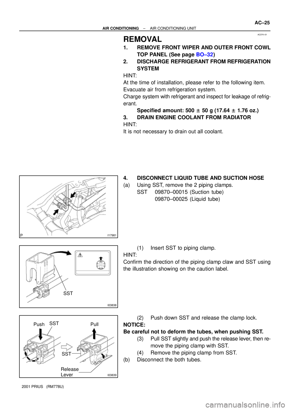
4. DISCONNECT LIQUID TUBE AND SUCTION HOSE
(a) Using SST, remove the 2 piping clamps.
SST 09870±00015 (Suction tube)
09870±00025 (Liquid tube)
(1) Insert SST to piping clamp.
HINT:
Confirm the direction of the piping clamp claw and SST using
the illustration showing on the caution label.
(2) Push down SST and release the clamp lock.
NOTICE:
Be careful not to deform the tubes, when pushing SST.
(3) Pull SST slightly and push the release lever, then re-
move the piping clamp with SST.
(4) Remove the piping clamp from SST.
(b) Disconnect the both tubes.
Page 1934 of 1943
AC36K±01
I18038 : Bulb
5
10
I07872
I17978
1
7
AC±78
± AIR CONDITIONINGHEATER CONTROL ASSEMBLY
2001 PRIUS (RM778U)
INSPECTION
1. INSPECT ILLUMINATION OPERATION
(a) Connect the positive (+) lead from the battery to terminal
5 and negative (±) lead to terminal 10, then check that the
illumination lights up.
If operation is not as specified, check the faulty bulb.
(b) Apply the tester as shown in the illustration to the test for
continuity.
If continuity exists, replace the heater control.
If no continuity exists, replace the bulb.
2. INSPECT INDICATOR OPERATION
Connect the positive (+) lead from the battery to terminal 1 and
negative (±) lead to terminal 7, then check that the illumination
light up.
If operation is not as specified, proceed next inspection.
Page 1935 of 1943

I18039
1
3
2 Dry Cell Batteries
I18040
1
5
2 Dry Cell Batteries
I18043
1 15
2 Dry Cell Batteries
I18044
6 8 14
13
± AIR CONDITIONINGHEATER CONTROL ASSEMBLY
AC±79
2001 PRIUS (RM778U)
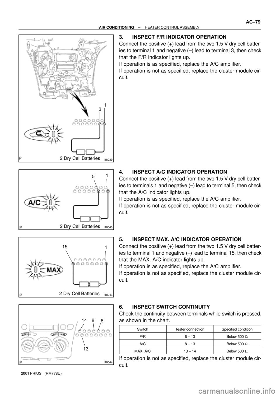
3. INSPECT F/R INDICATOR OPERATION
Connect the positive (+) lead from the two 1.5 V dry cell batter-
ies to terminal 1 and negative (±) lead to terminal 3, then check
that the F/R indicator lights up.
If operation is as specified, replace the A/C amplifier.
If operation is not as specified, replace the cluster module cir-
cuit.
4. INSPECT A/C INDICATOR OPERATION
Connect the positive (+) lead from the two 1.5 V dry cell batter-
ies to terminals 1 and negative (±) lead to terminal 5, then check
that the A/C indicator lights up.
If operation is as specified, replace the A/C amplifier.
If operation is not as specified, replace the cluster module cir-
cuit.
5. INSPECT MAX. A/C INDICATOR OPERATION
Connect the positive (+) lead from the two 1.5 V dry cell batter-
ies to terminal 1 and negative (±) lead to terminal 15, then check
that the MAX. A/C indicator lights up.
If operation is as specified, replace the A/C amplifier.
If operation is not as specified, replace the cluster module cir-
cuit.
6. INSPECT SWITCH CONTINUITY
Check the continuity between terminals while switch is pressed,
as shown in the chart.
SwitchTester connectionSpecified condition
F/R6 ± 13Below 500 W
A/C8 ± 13Below 500 W
MAX. A/C13 ± 14Below 500 W
If operation is not as specified, replace the cluster module cir-
cuit.