Page 1774 of 1943
I17862
Wire Harness Side
h±10±1±A
± BODY ELECTRICALHEADLIGHT AND TAILLIGHT SYSTEM
BE±21
2001 PRIUS (RM778U)
6. INSPECT DAYTIME RUNNING LIGHT MAIN RELAY
CIRCUIT
Disconnect the connector from the relay and inspect the con-
nector on the wire harness side.
Tester connectionConditionSpecified condition
2 ± GroundConstantContinuity
3 ± GroundConstantBattery voltage
4 ± GroundTerminal 5 groundBattery voltage
6 ± GroundConstantBattery voltage
7 ± GroundLight control switch OFF or TAILNo continuity
7 ± GroundLight control switch HEADContinuity
8 ± GroundHeadlight dimmer switch FLASH or HIContinuity
9 ± GroundEngine runningBattery voltage
12 ± GroundIgnition switch OFFNo voltage
12 ± GroundIgnition switch ONBattery voltage
If circuit is specified, try replacing the relay with a new one.
If circuit is not as specified, inspect the circuits connected to oth-
er parts.
Page 1775 of 1943
BE1CY±05
I23044
For Adjustment in
Vertical Direction
BE±22
± BODY ELECTRICALHEADLIGHT AND TAILLIGHT SYSTEM
2001 PRIUS (RM778U)
ADJUSTMENT
Page 1776 of 1943
 H 29.7 mm
(1.17 in.)
7
V RH Line
W90 °
V LH Line4
Low Beam:
V LH LineV Line V RH Line 65
6
29.7 mm
(1.17 in.)
High Beam:
V LH LineV Line V RH Line 6
5629.7 mm
(1.17 in.")
I17791
0.4 °
3 m (9.84 ft) H 29.7 mm
(1.17 in.)
7
V RH Line
W90 °
V LH Line4
Low Beam:
V LH LineV Line V RH Line 65
6
29.7 mm
(1.17 in.)
High Beam:
V LH LineV Line V RH Line 6
5629.7 mm
(1.17 in.)
29.7 mm
(1.17 in.) H 4
O: step No.
7
H4
W
W
± BODY ELECTRICALHEADLIGHT AND TAILLIGHT SYSTEM
BE±23
2001 PRIUS (RM778U)
ADJUST HEADLIGHT AIM ONLY
(a) Place the vehicle in the following conditions.
�The area around the headlight is not deformed.
�The vehicle is parked on a level surface.
�Tire inflation pressure is the specified value.
�A driver is in the driver's seat and the vehicle is in
a state ready for driving (with a tank full).
�The vehicle has been bounced several times.
(b) Check the headlight aiming.
(1) Prepare a thick white paper.
(2) Stand the paper perpendicular to the ground at the
position 9.84 ft away from the headlights.
(3) Ensure that the center line of the vehicle and the pa-
per face forms a 90±degree angle as shown in the
illustration.
(4) Draw a horizontal line (H line) on the paper, showing
where the headlights should strike.
(5) Draw a vertical line (V line) to where the center line
of the vehicle is to be.
(6) Draw 2 vertical lines (by connecting the low and
high beam center marks) to where the both head-
lights should strike (V RH and V LH lines).
(7) Draw a horizontal line (by connecting the both low
beam center marks) to where the headlights should
strike (H RH and H LH lines).
(8) Start the engine.
(9) Turn the headlights ON.
(10) Check that the headlights properly strike the posi-
tion shown in the illustration.
(11) If not, adjust the lights in the vertical direction.
HINT:
As shown in the illustration, adjust each aim of the RH and LH
lights.
(c) When adjusting it in the vertical direction:
Using adjusting bolt, adjust the headlight aim to within the
specified range.
Page 1777 of 1943

INSPECTION
1. INSPECT FRONT PERSONAL LIGHT CONTINUITY
Using an ohmmete")
BE1V0±02
I17855
I14261
2
I14287
ON
OFF
I11720
I01267
ON
OFF
± BODY ELECTRICALINTERIOR LIGHT SYSTEM
BE±27
2001 PRIUS (RM778U)
INSPECTION
1. INSPECT FRONT PERSONAL LIGHT CONTINUITY
Using an ohmmeter, check that continuity exists between termi-
nals.
If continuity is not as specified, replace the light assembly or
bulb.
2. INSPECT INTERIOR LIGHT CONTINUITY
(a) Disconnect the connector from the room light.
(b) Turn the room light switch ON, check that continuity exists
between terminal 1 and body ground.
If continuity is not as specified, replace the light assembly or
bulb.
3. INSPECT DOOR COURTESY SWITCH CONTINUITY
(a) Check that continuity exists between terminals and the
switch body with the switch ON (Switch pin released:
opened door).
(b) Check that no continuity exists between terminals and the
switch body with the switch OFF (Switch pin pushed in:
closed door).
If operation is not as specified, replace the switch.
4. INSPECT LICENCE PLATE LIGHT CONTINUITY
Using an ohmmeter, check that continuity exists between termi-
nals.
If continuity is not as specified, replace the light assembly or
bulb.
5. INSPECT LUGGAGE COMPARTMENT DOOR COUR-
TESY SWITCH CONTINUITY
(a) Check that continuity exists between terminals and the
switch body with the switch ON (Switch pin released:
opened door).
(b) Check that no continuity exists between terminals and the
switch body with the switch OFF (Switch pin pushed in:
closed door).
If operation is not as specified, replace the switch.
Page 1778 of 1943
I01268
1 2 BE±28
± BODY ELECTRICALINTERIOR LIGHT SYSTEM
2001 PRIUS (RM778U)
6. INSPECT LUGGAGE COMPARTMENT LIGHT CONTI-
NUITY
Using an ohmmeter, check that continuity exists between termi-
nals.
If continuity is not as specified, replace the light assembly or
bulb.
Page 1782 of 1943
BE1VS±02
I18849
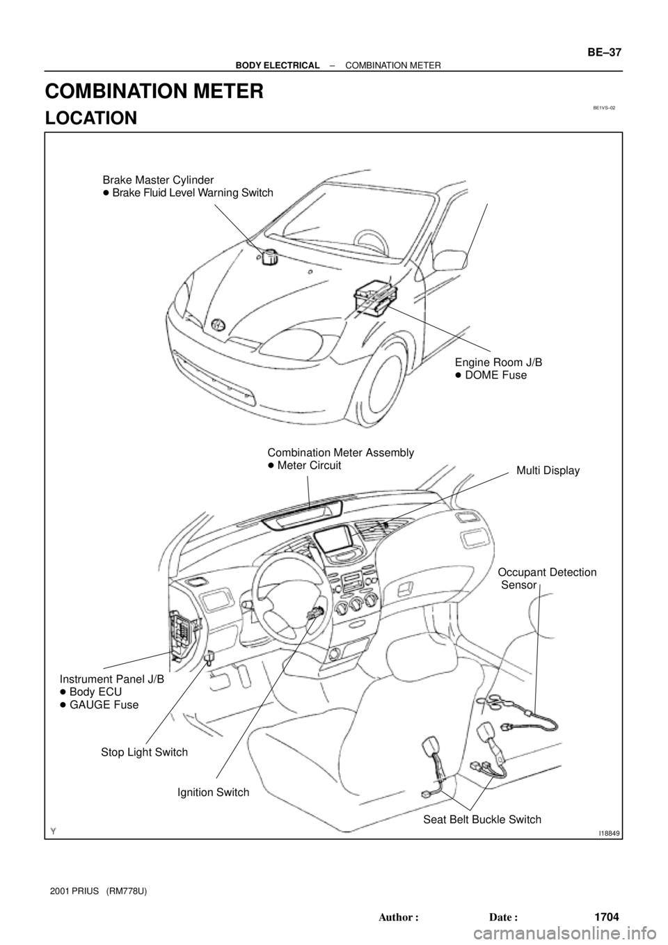
Brake Master Cylinder
� Brake Fluid Level Warning Switch
Combination Meter Assembly
� Meter Circuit
Multi Display
Ignition Switch
Instrument Panel J/B
� Body ECU
� GAUGE Fuse
Stop Light Switch
Engine Room J/B
� DOME Fuse
Seat Belt Buckle Switch
Occupant Detection
Sensor
± BODY ELECTRICALCOMBINATION METER
BE±37
1704 Author�: Date�:
2001 PRIUS (RM778U)
COMBINATION METER
LOCATION
Page 1786 of 1943
No. Wiring connector side
1
2
3
10
11
12
13
14
15
16
17
18
19
20
21
22EMPS ECU
Fuel tank temperature (+)
Hybrid vehicle control ECU (4P)
Ground
Ground
Center airbag sensor assembly
Headlight dimmer switch
Turn signal switch (Right)
Turn signal switch (Left)
Fuel tank temperature (±)
DOME Fuse
GAUGE FuseODO/TRIP switch (TC)
ODO/TRIP switch (E)
ODO/TRIP switch (ODO)
9 ABS ECU (SI)
ABS ECU (ABS)
2
3
4
5
6
7 1 Back±up light relay
Body ECU
Engine ECM
ACC Fuse
Light control rheostat (TC)
Light control rheostat (TR) A
BBody ECU
± BODY ELECTRICALCOMBINATION METER
BE±41
2001 PRIUS (RM778U)
Page 1787 of 1943

INSPECTION
1. INSPECT COMBINATION METER CIRCUIT
Disconnect connector ºAº and ºBº f")
BE1VU±02
I17803
Connector ºAº Connector ºBº BE±42
± BODY ELECTRICALCOMBINATION METER
2001 PRIUS (RM778U)
INSPECTION
1. INSPECT COMBINATION METER CIRCUIT
Disconnect connector ºAº and ºBº from the combination meter
and inspect the connectors on the wire harness side as shown
in the table.
Tester connectionConditionSpecified condition
A1 ± Ground
(ILL ± Body ground)Ignition switch ON and tail cancel switch ON or
OFFBelow 1V or 4.5 ± 5.5 V
A2 ± Ground
(E ± Body ground)ConstantContinuity
A3 ± Ground
(OPO ± Body ground)Ignition switch ON and trip reset switch ON or
OFFBelow 1V or 4.5 ± 5.5 V
A9 ± Ground
(SI ± Body ground)Ignition switch ON and slowly turn drive wheelBelow 1V or 10 ± 14 V
A10 ± Ground
(LP ± Body ground)Ignition switch ON and ABS indicator ON or OFFBelow 1V or 10 ± 14 V
A11 ± Ground
(L ± Body ground)Ignition switch ONPulse generation
A13 ± GroundI iti it h ON d l l t d i h lBelow 1V or 10 ± 14 VA13 Ground
(+S ± Body ground)Ignition switch ON and slowly turn drive wheelBelow 1V or 4.5 ± 5.5 V
A14 ± Ground
(ES ± Body ground)ConstantContinuity
A15 ± Ground
(EP ± Body ground)ConstantContinuity
A16 ± Ground
(SW ± Body ground)Ignition switch ON and air bag indicator light ON
or OFFBelow 1V or 10 ± 14 V
A17 ± Ground
(S ± Body ground)Headlight dimmer switch Hi or LowBelow 1V or 10 ± 14 V
A18 ± Ground
(B ± Body ground)Ignition switch ON and turn signal switch rightBelow 1V or 10 ± 14 V
A19 ± Ground
(B ± Body ground)Ignition switch ON and turn signal switch leftBelow 1V or 10 ± 14 V
A21 ± Ground
(B ± Body ground)Constant10 ± 14 V

6. INSPECT DAYTIME RUNNING LIGHT MAIN RELAY
CIRCUIT
Disconnect the connector from t")

ADJUSTMENT")

6. INSPECT LUGGAGE COMPARTMENT LIGHT CONTI-
NUITY
Using an ohmmeter, check that continuity exists between termi-
nals.
I")

Hybrid vehicle control ECU (4P)
Ground
Ground
Center airbag sensor assembly
Headlight dimmer sw")