Page 1789 of 1943

I17865
Fuel Sender Gauge Connector
I17865
Fuel Sender Gauge Connector
I01277
BatteryWarning Light Ignition
Switch
Wire Harness Side
1
I01278
BE±44
± BODY ELECTRICALCOMBINATION METER
2001 PRIUS (RM778U)
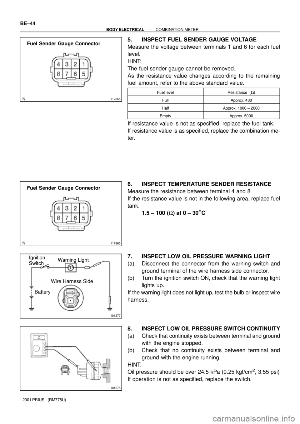
5. INSPECT FUEL SENDER GAUGE VOLTAGE
Measure the voltage between terminals 1 and 6 for each fuel
level.
HINT:
The fuel sender gauge cannot be removed.
As the resistance value changes according to the remaining
fuel amount, refer to the above standard value.
Fuel levelResistance (W)
FullApprox. 430
HalfApprox. 1000 ± 2000
EmptyApprox. 5000
If resistance value is not as specified, replace the fuel tank.
If resistance value is as specified, replace the combination me-
ter.
6. INSPECT TEMPERATURE SENDER RESISTANCE
Measure the resistance between terminal 4 and 8
If the resistance value is not in the following area, replace fuel
tank.
1.5 ± 100 (W) at 0 ± 30°C
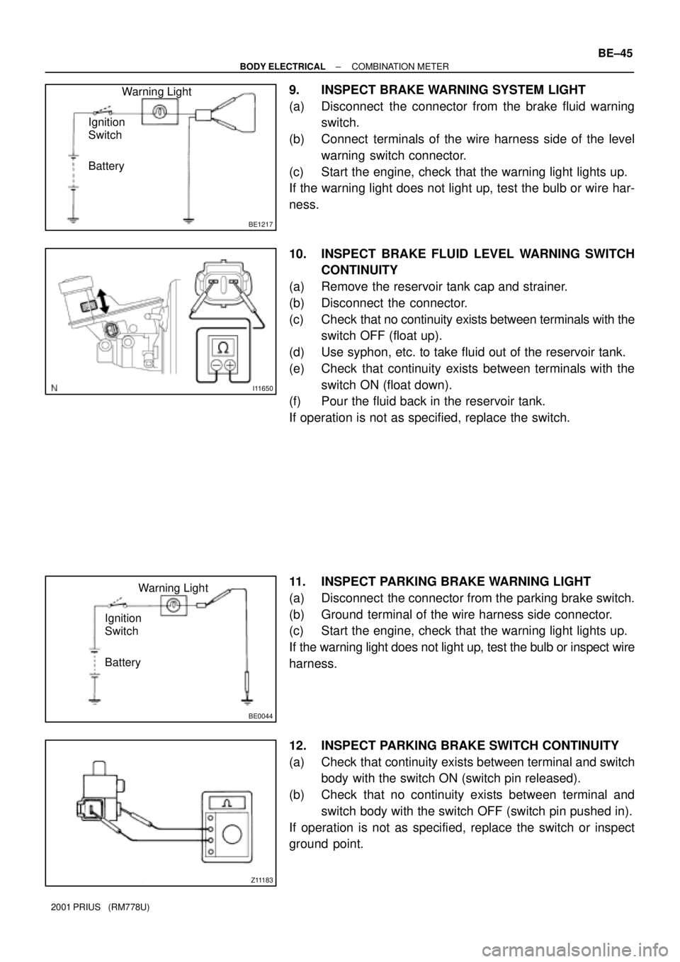
7. INSPECT LOW OIL PRESSURE WARNING LIGHT
(a) Disconnect the connector from the warning switch and
ground terminal of the wire harness side connector.
(b) Turn the ignition switch ON, check that the warning light
lights up.
If the warning light does not light up, test the bulb or inspect wire
harness.
8. INSPECT LOW OIL PRESSURE SWITCH CONTINUITY
(a) Check that continuity exists between terminal and ground
with the engine stopped.
(b) Check that no continuity exists between terminal and
ground with the engine running.
HINT:
Oil pressure should be over 24.5 kPa (0.25 kgf/cm
2, 3.55 psi)
If operation is not as specified, replace the switch.
Page 1790 of 1943

BE1217
BatteryWarning Light
Ignition
Switch
I11650
BE0044
BatteryWarning Light
Ignition
Switch
Z11183
± BODY ELECTRICALCOMBINATION METER
BE±45
2001 PRIUS (RM778U)
9. INSPECT BRAKE WARNING SYSTEM LIGHT
(a) Disconnect the connector from the brake fluid warning
switch.
(b) Connect terminals of the wire harness side of the level
warning switch connector.
(c) Start the engine, check that the warning light lights up.
If the warning light does not light up, test the bulb or wire har-
ness.
10. INSPECT BRAKE FLUID LEVEL WARNING SWITCH
CONTINUITY
(a) Remove the reservoir tank cap and strainer.
(b) Disconnect the connector.
(c) Check that no continuity exists between terminals with the
switch OFF (float up).
(d) Use syphon, etc. to take fluid out of the reservoir tank.
(e) Check that continuity exists between terminals with the
switch ON (float down).
(f) Pour the fluid back in the reservoir tank.
If operation is not as specified, replace the switch.
11. INSPECT PARKING BRAKE WARNING LIGHT
(a) Disconnect the connector from the parking brake switch.
(b) Ground terminal of the wire harness side connector.
(c) Start the engine, check that the warning light lights up.
If the warning light does not light up, test the bulb or inspect wire
harness.
12. INSPECT PARKING BRAKE SWITCH CONTINUITY
(a) Check that continuity exists between terminal and switch
body with the switch ON (switch pin released).
(b) Check that no continuity exists between terminal and
switch body with the switch OFF (switch pin pushed in).
If operation is not as specified, replace the switch or inspect
ground point.
Page 1791 of 1943
BE0044
BatteryWarning Light
Ignition
Switch BE±46
± BODY ELECTRICALCOMBINATION METER
2001 PRIUS (RM778U)
13. INSPECT OPEN DOOR WARNING LIGHT
Disconnect the connector from the door courtesy switch, and
ground terminal 1 of the wire harness side connector and check
that the warning light lights up.
If the warning light does not light up, inspect the bulb or wire har-
ness.
Page 1792 of 1943

BE1D5±03
I17792
8 71
I17793
I01200
2 1
35
2 5
1 3
± BODY ELECTRICALDEFOGGER SYSTEM
BE±49
2001 PRIUS (RM778U)
INSPECTION
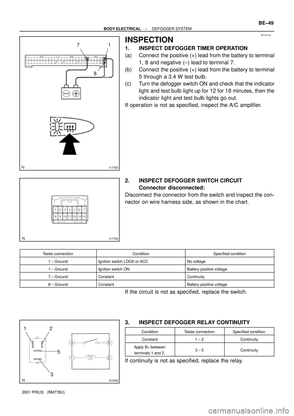
1. INSPECT DEFOGGER TIMER OPERATION
(a) Connect the positive (+) lead from the battery to terminal
1, 8 and negative (±) lead to terminal 7.
(b) Connect the positive (+) lead from the battery to terminal
5 through a 3.4 W test bulb.
(c) Turn the defogger switch ON and check that the indicator
light and test bulb light up for 12 for 18 minutes, then the
indicator light and test bulb lights go out.
If operation is not as specified, inspect the A/C amplifier.
2. INSPECT DEFOGGER SWITCH CIRCUIT
Connector disconnected:
Disconnect the connector from the switch and inspect the con-
nector on wire harness side, as shown in the chart.
Tester connectionConditionSpecified condition
1 ± GroundIgnition switch LOCK or ACCNo voltage
1 ± GroundIgnition switch ONBattery positive voltage
7 ± GroundConstantContinuity
8 ± GroundConstantBattery positive voltage
If the circuit is not as specified, replace the switch.
3. INSPECT DEFOGGER RELAY CONTINUITY
ConditionTester connectionSpecified condition
Constant1 ± 2Continuity
Apply B+ between
terminals 1 and 2.3 ± 5Continuity
If continuity is not as specified, replace the relay.
Page 1794 of 1943

BE1V2±01
I17845
Power WIndow Master Switch
1 One touch power window does not move up and down.
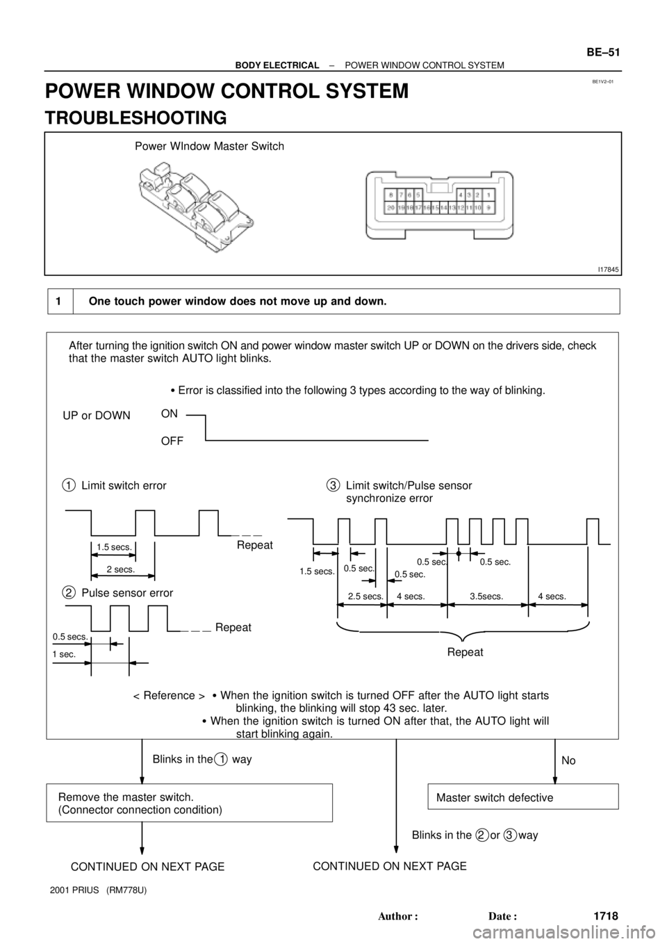
After turning the ignition switch ON and power window master switch UP or DOWN on the drivers side, check
that the master switch AUTO light blinks.
� Error is classified into the following 3 types according to the way of blinking.
UP or DOWNON
OFF
1 Limit switch error 3 Limit switch/Pulse sensor
synchronize error
1.5 secs.
2 secs.Repeat
1.5 secs.0.5 sec.
No Repeat 2 Pulse sensor error
Repeat
< Reference > � When the ignition switch is turned OFF after the AUTO light starts
blinking, the blinking will stop 43 sec. later.
� When the ignition switch is turned ON after that, the AUTO light will
start blinking again.
0.5 secs.
Blinks in the 1 way
Remove the master switch.
(Connector connection condition)Master switch defective
Blinks in the 2 or 3 way
1 sec.
CONTINUED ON NEXT PAGECONTINUED ON NEXT PAGE
0.5 sec.0.5 sec. 0.5 sec.
2.5 secs. 4 secs. 4 secs.3.5secs.
± BODY ELECTRICALPOWER WINDOW CONTROL SYSTEM
BE±51
1718 Author�: Date�:
2001 PRIUS (RM778U)
POWER WINDOW CONTROL SYSTEM
TROUBLESHOOTING
Page 1806 of 1943

DI7T9±01
± BODY ELECTRICALTHEFT DETERRENT SYSTEM
BE±67
2001 PRIUS (RM778U)
PRE±CHECK
1. OUT LINE OF THEFT DETERRENT SYSTEM
When the theft deterrent system detects any theft, it informs
people around with flashing lights and sound.
This system is designed to be upgraded by featuring an option-
al glass break sensor.
All initial setting are performed in active mode. It can be
switched to passive mode by specified operation. (See step 3.
CHANGING METHOD OF PASSIVE MODE)
HINT:
There are 4 conditions in this system which are disarmed state,
arming preparation, armed state and alarm sounding.
(1) Disarmed state
�When the alarming function does not oper-
ate.
�When theft deterrent function is not per-
formed.
(2) Arming preparation
�Time until transferring to armed state.
�Theft deterrent function is not performed.
(3) Armed state
When theft deterrent function is possible.
(4) Alarm sounding:
In this condition, once theft is detected, it is in-
formed using light and sound to people around the
vehicle.
Refer to the table for alarming method or time.
Horn
Security horn
Al i th dHeadlightAlarming methodTaillight
Hazard
Interior light
Alarming time60 seconds
Alarming outputContinuous 0.4 secs. (ON)
0.4 secs. (OFF)
HINT:
Alarming output for hazard is same as the one for the hazard
on the vehicle.
In the arming condition when either of doors is unlocked with
key not in the key cylinder, force lock signal is output.
Page 1807 of 1943

Disarmed state
Perform any of the following and the system will go no to ºArming preparationº:
� With all the doors, engine hood and luggage compartment door closed, lock all doors with the key.
� With all the doors, engine hood and luggage compartment door closed, lock all doors with the
wireless remote.
� With all the doors, engine hood and luggage compartment door closed, open and close any of doors,
engine hood or luggage compartment door, then close and lock all doors, engine hood and luggage
compartment door.
Arming preparation
Perform the following and the system will
go on to ºArmed stateº:
� Let 30 seconds elapse with all the doors,
engine hood and luggage compartment door
closed and locked.
Perform any of the following and the system
will return to ºDisarmed stateº:
� Open any of the doors, engine hood or luggage
compartment door.
� Unlock any of the doors.
� Put the key in the ignition.
� Reconnect the battery.
Armed state
Perform any of the following and the system
will return to ºDisarmed stateº:
� Unlock any of the doors or open the luggage
compartment door with the wireless remote.
� Unlock the doors with the wireless remote.
� Put the key in the ignition and turn it to ON.
Perform any of the following and the system
will go on to ºAlarm soundingº:
� Open any of the doors.
� Unlock any of the doors in any way other than
with a key or the wireless remote.
� Open the luggage compartment door in any way
other than with a key.
� Open the engine hood.
� Reconnect the battery.
� When input from optional glass break sensor is
detected (Dealer option)(Key not inserted in ignition.)
Alarm sounding
The vehicle's horn and security horn will sound,
and the hazard, interior, tail and head lights flash
for 60 seconds.
After the alarm has ended, the system will
return to ºArmed stateº. Perform any of the following and the system
will return to ºDisarmed stateº:
� Unlock any of the doors or open the luggage
compartment door with the wireless remote.
� Unlock the doors with the wireless remote.
� Put the key in the ignition and turn it to ON.
BE±68
± BODY ELECTRICALTHEFT DETERRENT SYSTEM
2001 PRIUS (RM778U)
2. ACTIVE ARMING MODE
Page 1808 of 1943
± BODY ELECTRICALTHEFT DETERRENT SYSTEM
BE±69
2001 PRIUS (RM778U)
Indicator light output:
ConditionIndicator light
Disarmed stateOFF
Arming preparationON
Armed stateOFF
Alarm soundingON
HINT:
Even in disarmed state, the indicator light flash. (Due to the sig-
nal output form immobilizer system). The indicator always
flashes receiving the signal from the immobilizer system at any
time in the armed state.
Flashing frequency:
0.2 seconds (ON)
1.8 seconds (OFF)
Answer back:
The hazard lights flush as answer back under the following
conditions.
(1) When the system is set.
When arming preparation is set from disarmed state
using the wireless door lock, the hazard lights flush
once.
(2) When the system is released.
When disarmed state is set from either arming prep-
aration, armed state or alarm sounding using the
wireless door lock, the hazard lights flush twice.