Page 1722 of 1943

6. SRS WARNING LIGHT
The SRS warning light is located on the combination meter. It
goes on to alert t")
H15218
H15513
H15517
H15675
± SUPPLEMENTAL RESTRAINT SYSTEMSRS AIRBAG
RS±3
2001 PRIUS (RM778U)
6. SRS WARNING LIGHT
The SRS warning light is located on the combination meter. It
goes on to alert the driver of trouble in the system when a mal-
function is detected in the airbag sensor assembly self±diagno-
sis. In normal operation conditions when the ignition switch is
turned to the ON position, the light goes on for about 6 seconds
and then goes off.
7. AIRBAG SENSOR ASSEMBLY
The airbag sensor assembly is mounted on the floor inside the
lower center finish panel. The airbag sensor assembly consists
of an airbag sensor, safing sensor, diagnosis circuit, ignition
control, drive circuit, etc. It receives signals from the airbag sen-
sor, front airbag sensor, side airbag sensor assembly and door
side airbag assembly and judges whether the SRS must be ac-
tivated or not. The airbag sensor assembly cannot be disas-
sembled.
8. FRONT AIRBAG SENSOR
The front airbag sensor is mounted inside each of the side
members. The sensor unit is a mechanical type. When the sen-
sor detects deceleration force above a predetermined limit,
contact is made in the sensor, sending a signal to the airbag
sensor assembly. The front airbag sensor cannot be disas-
sembled.
9. SIDE AIRBAG SENSOR ASSEMBLY
The side airbag sensor assembly is mounted in the LH and RH
center pillars. The side airbag sensor assembly consists of a lat-
eral deceleration sensor, safing sensor, diagnosis circuit, etc.
It sends signals to the airbag sensor assembly to judge whether
the SRS side airbag must be activated or not. The side airbag
sensor assembly cannot be disassembled.
Page 1725 of 1943
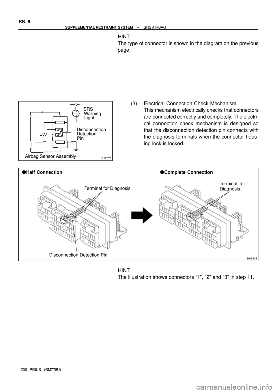
R12076Airbag Sensor AssemblyDisconnection
Detection
PinSRS
Warning
Light
H01315
Terminal for Diagnosis
Disconnection Detection Pin �Half Connection�Complete Connection
Terminal for
Diagnosis
RS±6
± SUPPLEMENTAL RESTRAINT SYSTEMSRS AIRBAG
2001 PRIUS (RM778U)
HINT:
The type of connector is shown in the diagram on the previous
page.
(3) Electrical Connection Check Mechanism
This mechanism electrically checks that connectors
are connected correctly and completely. The electri-
cal connection check mechanism is designed so
that the disconnection detection pin connects with
the diagnosis terminals when the connector hous-
ing lock is locked.
HINT:
The illustration shows connectors º1º, º2º and º3º in step 11.
Page 1727 of 1943
H01583
Outer
Outer
RS±8
± SUPPLEMENTAL RESTRAINT SYSTEMSRS AIRBAG
2001 PRIUS (RM778U)
12. CONNECTION OF CONNECTORS FOR FRONT AIR-
BAG SENSOR AND SIDE AIRBAG SENSOR
(a) Align the male connector (of the side of sensor) and fe-
male connector in the same direction as shown in the il-
lustration and fit in them without rubbing.
(b) As they are fitted in, the outer slides rearward. Press it un-
til the outer returns to its original position again.
If fitting stops half way, connectors will separate.
(c) Be sure to insert until they are locked. After fitting in, pull
them slightly to check that they are locked. (When locked,
make sure that the outer returns to its original position and
sound at the time of fitting in can be heard.)
HINT:
�Do not fit in while holding the outer.
�When fitting in, the outer slides. Do not touch it.
Page 1729 of 1943
H01586
Slider
Disconnection is completed Slider
RS±10
± SUPPLEMENTAL RESTRAINT SYSTEMSRS AIRBAG
2001 PRIUS (RM778U)
(a) Align a lock part of male connector and a slider of female
connector in the same direction as shown in the illustra-
tion, fit in them without rubbing.
(b) Be sure to insert until they are locked. After fitting in pull
them slightly to check that they are locked. (When locked,
make sure that the outer returns to its original position and
sound at the time of fitting in can be heard.)
HINT:
�As the slider slides, do not touch it.
�Be careful not to deform the release board. If the release
board is deformed, replace it with a new one.
15. DISCONNECTION OF CONNECTORS FOR STEERING
WHEEL PAD (with AIRBAG) AND FRONT PAS-
SENGER AIRBAG ASSEMBLY
(a) Place a finger on the slider.
(b) Slide the slider to release lock.
(c) Disconnect the connector.
Page 1730 of 1943
H01587
Slider
Slider
± SUPPLEMENTAL RESTRAINT SYSTEMSRS AIRBAG
RS±11
2001 PRIUS (RM778U)
16. CONNECTION OF CONNECTORS FOR STEERING
WHEEL PAD (with AIRBAG) AND FRONT PAS-
SENGER AIRBAG ASSEMBLY
(a) Align a lock part of male connector and a slider of female
connector in the same direction as shown in the illustra-
tion, fit in them without rubbing.
(b) Be sure to insert until they are locked. After fitting in pull
them slightly to check that they are locked. (When locked,
make sure that the outer returns to its original position and
sound at the time of fitting in can be heard.)
HINT:
�As the slider slides, do not touch it.
�Be careful not to deform the release board. If the release
board is deformed, replace it with a new one.
Page 1734 of 1943

(a) Check functioning of the SST.
CAUTION:
Whe")
AB0152
SST
AB0158
SSTBattery
H01580
SST
H15221
H16242SST
± SUPPLEMENTAL RESTRAINT SYSTEMSTEERING WHEEL PAD AND SPIRAL CABLE
RS±17
2001 PRIUS (RM778U)
(a) Check functioning of the SST.
CAUTION:
When deploying the airbag, always use the specified SST:
SRS Airbag Deployment Tool.
SST 09082±00700
(1) Connect the red clip of the SST to the battery posi-
tive (+) terminal and the black clip to the battery neg-
ative (±) terminal.
HINT:
Do not connect the yellow connector which will be connected
with the supplemental restraint system.
(2) Press the SST activation switch, and check that the
LED of the SST activation switch lights up.
CAUTION:
If the LED lights up when the activation switch is not being
pressed, SST malfunction is probable, so definitely do not
use the SST.
(3) Disconnect the SST from the battery.
(b) Install the SST.
CAUTION:
Check that there is no looseness in the steering wheel and
steering wheel pad.
(1) While turning the steering wheel right / left, remove
the 3 screws and column lower cover.
(2) Disconnect the airbag connector of the spiral cable.
(3) Connect the connectors of the 2 SST to the airbag
connector of the spiral cable.
SST 09082±00700, 09082±00760
NOTICE:
To avoid damaging the connector of the SST and wire har-
ness, do not lock the secondary lock of the twin lock.
Page 1735 of 1943
 or more
SSTBattery
R06753
RS±18
± SUPPLEMENTAL RESTRAINT SYSTEMSTEERING WHEEL PAD AND SPIRAL CABLE
2001 PRIUS (RM778U)
(4) Move the SST at least 10 m (33 ft) away from the
fron")
R13455
10 m (33 ft) or more
SSTBattery
R06753
RS±18
± SUPPLEMENTAL RESTRAINT SYSTEMSTEERING WHEEL PAD AND SPIRAL CABLE
2001 PRIUS (RM778U)
(4) Move the SST at least 10 m (33 ft) away from the
front of the vehicle.
(5) Close all the doors and windows of the vehicle.
NOTICE:
Take care not to damage the SST wire harness.
(6) Connect the SST red clip to the battery positive (+)
terminal and the black clip to the negative (±) termi-
nal.
(c) Deploy the airbag.
(1) Check that no one is inside the vehicle or within 10
m (33 ft) area around the vehicle.
(2) Press the SST activation switch and deploy the air-
bag.
CAUTION:
�The steering wheel pad is very hot when the airbag is
deployed, so leave it alone for at least 30 minutes af-
ter deployment.
�Use gloves and safety glasses when handling a steer-
ing wheel pad with the deployed airbag.
�Always wash your hands with water after completing
the operation.
�Do not apply water, etc. to a steering wheel pad with
the deployed airbag.
�When scrapping a vehicle, deploy the airbag and
scrap the vehicle with the steering wheel pad still
installed.
�When moving a vehicle for scrapping which has a
steering wheel pad with deployed airbag, use gloves
and safety glasses.
HINT:
The airbag deploys simultaneously as the LED of the SST ac-
tivation switch lights up.
2. DEPLOYMENT WHEN DISPOSING OF STEERING
WHEEL PAD ONLY
NOTICE:
�When disposing of the steering wheel pad (with air-
bag) only, never use the customers vehicle to deploy
the airbag.
�Be sure to follow the procedure given below when de-
ploying the airbag.
HINT:
Have a battery ready as the power source to deploy the airbag.
Page 1739 of 1943
Width
H03207
10 m (33 ft) or more
H03208
RS±22
± SUPPLEMENTAL RESTRAINT SYSTEMSTEERING WHEEL PAD AND SPIRAL CABLE
2001 PRIUS (RM778U)
�Covering method using ti")
H03206
Inner Diam.
Tires
(3 or More)Width
H03207
10 m (33 ft) or more
H03208
RS±22
± SUPPLEMENTAL RESTRAINT SYSTEMSTEERING WHEEL PAD AND SPIRAL CABLE
2001 PRIUS (RM778U)
�Covering method using tires:
Place at least 3 tires without disc wheel on top of the
disc wheel with tire to which the steering wheel pad
is tied.
Tire size: Must exceed the following dimensions±
Width: 185 mm (7.87 in.)
Inner diameter: 360 mm (14.17 in.)
CAUTION:
Do not use tires with disc wheels.
NOTICE:
The tires may be marked by the airbag deployment, so use
the redundant tires.
(f) Deploy the airbag.
(1) Connect the SST red clip to the battery positive (+)
terminal and the black clip to the battery negative
(±) terminal.
(2) Check that no one is within 10 m (33 ft) area around
the disc wheel which the steering wheel pad is tied
to.
(3) Press the SST activation switch and deploy the air-
bag.
HINT:
The airbag deploys simultaneously as the LED of the SST ac-
tivation switch lights up.
(g) Dispose of the steering wheel pad (with airbag).
CAUTION:
�The steering wheel pad is very hot when the airbag is
deployed, so leave it alone for at least 30 minutes af-
ter deployment.
�Use gloves and safety glasses when handling a steer-
ing wheel pad with the deployed airbag.
�Always wash your hands with water after completing
the operation.
�Do not apply water, etc. to a steering wheel pad with
the deployed airbag.
(1) Remove the steering wheel pad from the disc
wheel.
(2) Place the steering wheel pad in a vinyl bag, tie the
end tightly and dispose of it in the same way as oth-
er general parts disposal.

12. CONNECTION OF CONNECTORS FOR FRONT AIR-
BAG SENSOR AND SIDE AIRBAG SENSOR
(a) Align the male connector (o")

(a) Align a lock part of male connector and a slider of female
connector in the")

16. CONNECTION OF CONNECTORS FOR STEERING
WHEEL PAD (with AIRBAG) AND FRONT PAS-
SENGER AIRBAG ASSEMBLY
(a)")