Page 1451 of 1943
I18174
ON
HTR2(+) (±)
DI±944
± DIAGNOSTICSAIR CONDITIONING SYSTEM
2001 PRIUS (RM778U)
INSPECTION PROCEDURE
1 Check converter circuit (See page DI±934).
2 Check voltage between terminal HTR2 of A/C amplifier and body ground.
PREPARATION:
Remove the center cluster module control with connectors still
connected.
CHECK:
(a) Start engine.
(b) Set temperature control switch on ºMAX. WARMº posi-
tion.
(c) Set blower switch on ºHIº position.
(d) Turn light control switch OFF.
(e) Turn defogger switch OFF.
(f) Check voltage between terminal HTR2 of A/C amplifier
and body ground at each conditions, as shown in the
chart.
OK:
ConditionVoltage
�Air flow selector: FOOT
�Water temp. : Below 65°C (149°F)Below 0.7 V
�Air flow selector: FOOT/DEF
�Water temp. : Below 60°C (140°F)Below 0.7 V
�Air flow selector: DEF
�Water temp. : 75°C (167°F)Below 0.7 V
OK Go to step 6.
NG
Page 1456 of 1943
I18152
ON
HTR0
(+)
(±)
± DIAGNOSTICSAIR CONDITIONING SYSTEM
DI±949
2001 PRIUS (RM778U)
INSPECTION PROCEDURE
1 Check converter circuit (See page DI±934).
2 Check voltage between terminal HTR0, of A/C amplifier and body ground.
PREPARATION:
Remove the center cluster module control with connectors still
connected.
CHECK:
(a) Start engine.
(b) Set temperature control switch on ºMAX WARMº position.
(c) Set blower switch on ºHIº position.
(d) Turn light control switch to OFF.
(e) Turn defogger switch OFF.
(f) Check voltage between terminal HTR0 of A/C amplifier
and body ground at each conditions, as shown in the
chart.
OK:
ConditionVoltage
�Air flow selector: FOOT
�Water temp. : Below 60°C (140°F)Below 0.7 V
�Air flow selector: FOOT/DEF
�Water temp. : Below 50°C (122°F)Below 0.7 V
OK Go to step 6.
NG
Page 1494 of 1943

EM2534
Overall Length
A01073
45° Carbide
CutterResiduary
Width
Resurface
A01074
Width
EM0185
45°20°
1.0 ± 1.4 mm
EM0186
75°
1.0 ± 1.4 mm45°
EM±36
± ENGINE MECHANICALCYLINDER HEAD
2001 PRIUS (RM778U)
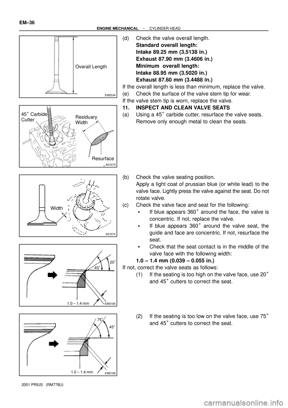
(d) Check the valve overall length.
Standard overall length:
Intake 89.25 mm (3.5138 in.)
Exhaust 87.90 mm (3.4606 in.)
Minimum overall length:
Intake 88.95 mm (3.5020 in.)
Exhaust 87.60 mm (3.4488 in.)
If the overall length is less than minimum, replace the valve.
(e) Check the surface of the valve stem tip for wear.
If the valve stem tip is worn, replace the valve.
11. INSPECT AND CLEAN VALVE SEATS
(a) Using a 45° carbide cutter, resurface the valve seats.
Remove only enough metal to clean the seats.
(b) Check the valve seating position.
Apply a light coat of prussian blue (or white lead) to the
valve face. Lightly press the valve against the seat. Do not
rotate valve.
(c) Check the valve face and seat for the following:
�If blue appears 360° around the face, the valve is
concentric. If not, replace the valve.
�If blue appears 360° around the valve seat, the
guide and face are concentric. If not, resurface the
seat.
�Check that the seat contact is in the middle of the
valve face with the following width:
1.0 ± 1.4 mm (0.039 ± 0.055 in.)
If not, correct the valve seats as follows:
(1) If the seating is too high on the valve face, use 20°
and 45° cutters to correct the seat.
(2) If the seating is too low on the valve face, use 75°
and 45° cutters to correct the seat.
Page 1502 of 1943
S05923
Intake Exhaust
Mark
ºNOKº
Gray Surface
Light Brown Surface
A01065
(1)
(2)(3)
(4)
A01061
SST
A07307
EM±44
± ENGINE MECHANICALCYLINDER HEAD
2001 PRIUS (RM778U)
HINT:
The intake valve oil seal is light brown and the exhaust valve oil
seal is gray.
NOTICE:
Pay much attention assembling the oil seal for intake and
exhaust. Assembling the wrong one may cause a failure.
(b) Install the valve (1), spring (2), valve spring (3), and spring
retainer (4).
(c) Using SST, compress the valve spring and place the 2
keepers around the valve stem.
SST 09202±70020 (09202±00010)
(d) Using a plastic±faced hammer and the valve stem (not in
use) tip wound with vinyl tape, lightly tap the valve stem
tip to ensure a proper fit.
NOTICE:
Be careful not to damage the valve stem tip.
3. INSTALL VALVE LIFTERS
(a) Install the valve lifter.
(b) Check that the valve lifter rotates smoothly by hand.
Page 1503 of 1943

EM1IY±02
A11249
Lod No.
A11228
84259
106137
A12126
Front90°90°
± ENGINE MECHANICALCYLINDER HEAD
EM±45
2001 PRIUS (RM778U)
INSTALLATION
HINT:
�Thoroughly clean all parts to be assembled.
�Before installing the parts, apply fresh engine oil to all slid-
ing and rotating surfaces.
�Replace all gaskets and oil seals with new ones.
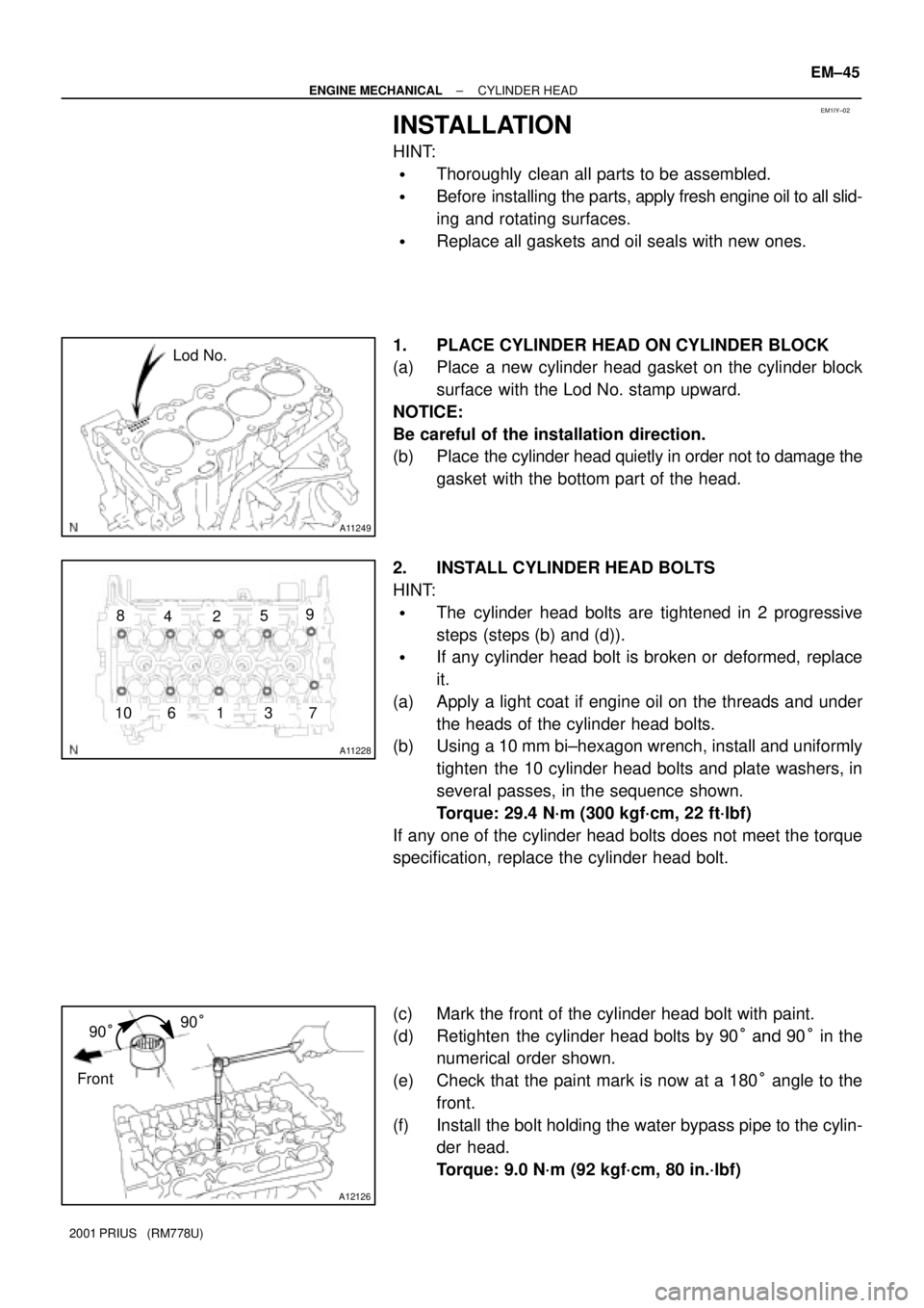
1. PLACE CYLINDER HEAD ON CYLINDER BLOCK
(a) Place a new cylinder head gasket on the cylinder block
surface with the Lod No. stamp upward.
NOTICE:
Be careful of the installation direction.
(b) Place the cylinder head quietly in order not to damage the
gasket with the bottom part of the head.
2. INSTALL CYLINDER HEAD BOLTS
HINT:
�The cylinder head bolts are tightened in 2 progressive
steps (steps (b) and (d)).
�If any cylinder head bolt is broken or deformed, replace
it.
(a) Apply a light coat if engine oil on the threads and under
the heads of the cylinder head bolts.
(b) Using a 10 mm bi±hexagon wrench, install and uniformly
tighten the 10 cylinder head bolts and plate washers, in
several passes, in the sequence shown.
Torque: 29.4 N´m (300 kgf´cm, 22 ft´lbf)
If any one of the cylinder head bolts does not meet the torque
specification, replace the cylinder head bolt.
(c) Mark the front of the cylinder head bolt with paint.
(d) Retighten the cylinder head bolts by 90° and 90° in the
numerical order shown.
(e) Check that the paint mark is now at a 180° angle to the
front.
(f) Install the bolt holding the water bypass pipe to the cylin-
der head.
Torque: 9.0 N´m (92 kgf´cm, 80 in.´lbf)
Page 1504 of 1943

A12945
No.1 Cam Lobe
A12946
A12943
9
9
96
5
2
1
4
3
8
7 EM±46
± ENGINE MECHANICALCYLINDER HEAD
2001 PRIUS (RM778U)
(g) Connect the upper radiator hose to the water hose
unions.
(h) Connect the heater hose to the water hose unions.
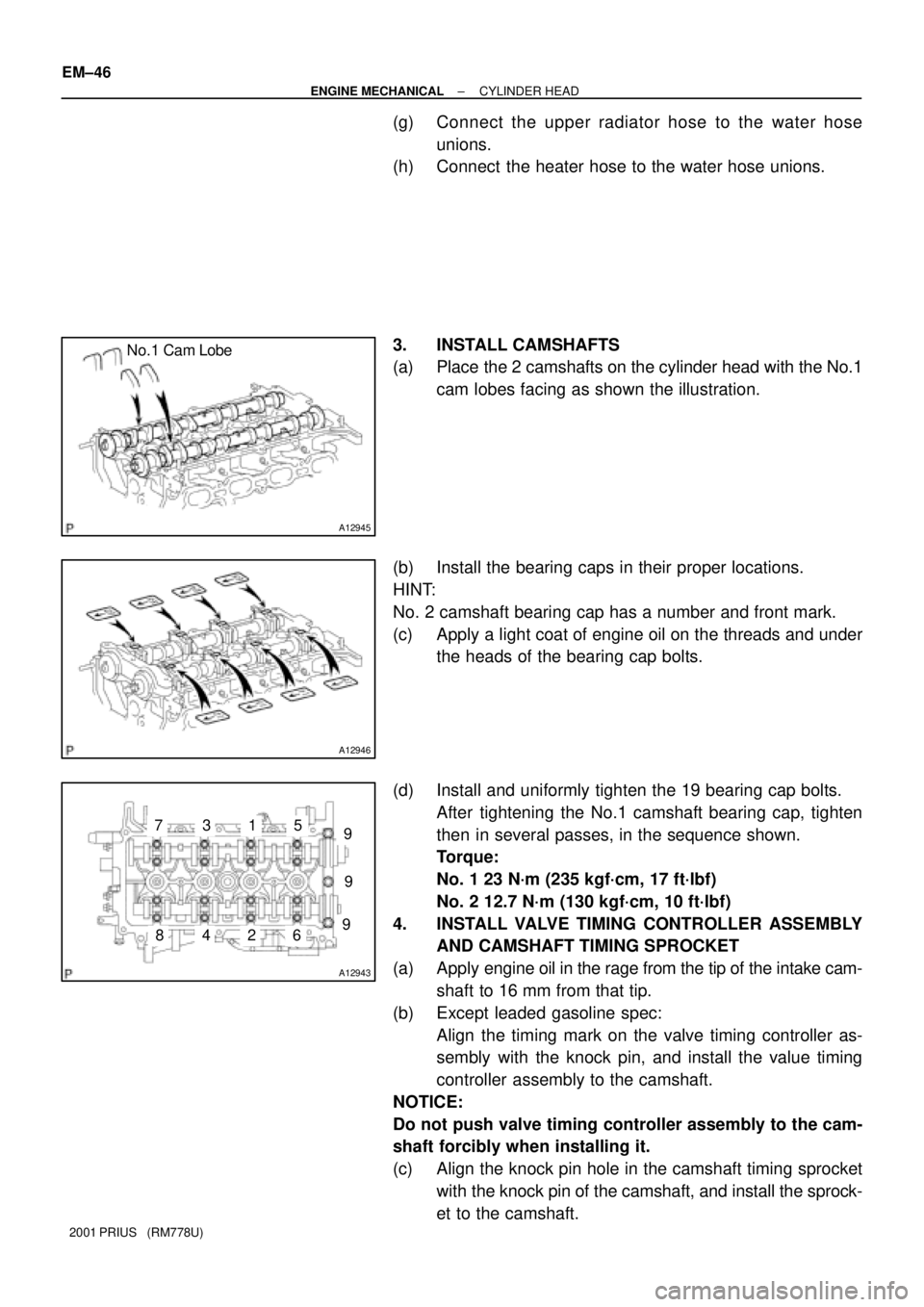
3. INSTALL CAMSHAFTS
(a) Place the 2 camshafts on the cylinder head with the No.1
cam lobes facing as shown the illustration.
(b) Install the bearing caps in their proper locations.
HINT:
No. 2 camshaft bearing cap has a number and front mark.
(c) Apply a light coat of engine oil on the threads and under
the heads of the bearing cap bolts.
(d) Install and uniformly tighten the 19 bearing cap bolts.
After tightening the No.1 camshaft bearing cap, tighten
then in several passes, in the sequence shown.
Torque:
No. 1 23 N´m (235 kgf´cm, 17 ft´lbf)
No. 2 12.7 N´m (130 kgf´cm, 10 ft´lbf)
4. INSTALL VALVE TIMING CONTROLLER ASSEMBLY
AND CAMSHAFT TIMING SPROCKET
(a) Apply engine oil in the rage from the tip of the intake cam-
shaft to 16 mm from that tip.
(b) Except leaded gasoline spec:
Align the timing mark on the valve timing controller as-
sembly with the knock pin, and install the value timing
controller assembly to the camshaft.
NOTICE:
Do not push valve timing controller assembly to the cam-
shaft forcibly when installing it.
(c) Align the knock pin hole in the camshaft timing sprocket
with the knock pin of the camshaft, and install the sprock-
et to the camshaft.
Page 1508 of 1943
EM1IZ±02
A13904
Front BumperR/B (ABS)
Air Cleaner
Assembly Engine Coolant
Reservoir Tank
Engine Under
CoverOuter Front Cowl
Top Panel Air Inlet
Brake Reservoir
Tank
Wiper Motor and
Wiper Link
Assembly
Cowl Top Ventilator
Lower LH
Cowl Top Ventilator
Lower RH
Wiper Arm
Hood to Cowl Top
Seal
N´m (kgf´cm, ft´lbf) : Specified torque
26 (265, 19)
7 (71, 62 in. lbf)
26 (265, 19)
11.5 (117, 8)
Head Light RH
EM±50
± ENGINE MECHANICALENGINE UNIT
1166 Author�: Date�:
2001 PRIUS (RM778U)
ENGINE UNIT
COMPONENTS
Page 1515 of 1943

EM1J2±02
P08755
A13917
SSTSST
1
2
3
4
6
5
A13940
SST
A13917
SSTSST
1
2
3
4
6
5
EM±58
± ENGINE MECHANICALENGINE UNIT
2001 PRIUS (RM778U)
INSTALLATION
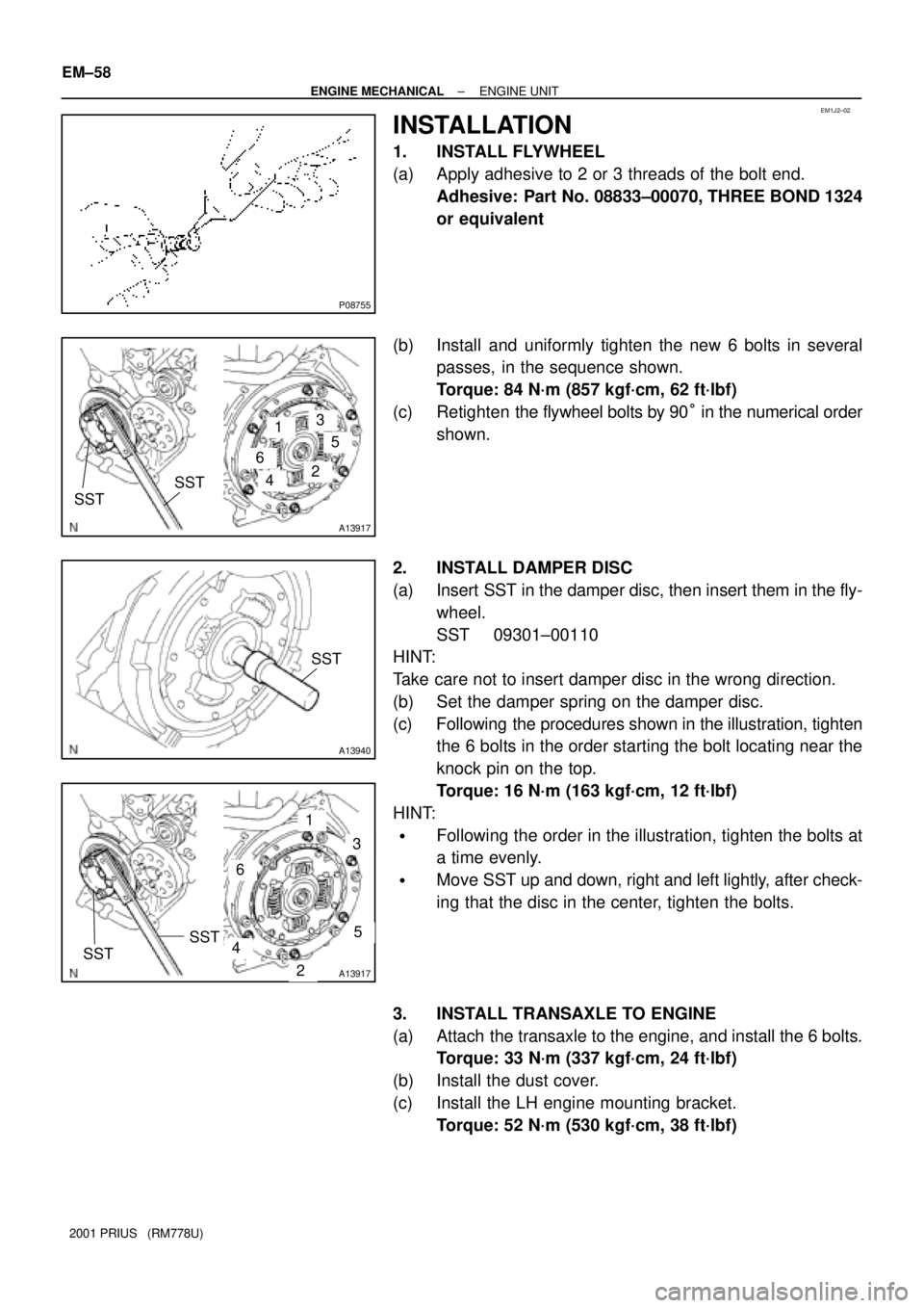
1. INSTALL FLYWHEEL
(a) Apply adhesive to 2 or 3 threads of the bolt end.
Adhesive: Part No. 08833±00070, THREE BOND 1324
or equivalent
(b) Install and uniformly tighten the new 6 bolts in several
passes, in the sequence shown.
Torque: 84 N´m (857 kgf´cm, 62 ft´lbf)
(c) Retighten the flywheel bolts by 90° in the numerical order
shown.
2. INSTALL DAMPER DISC
(a) Insert SST in the damper disc, then insert them in the fly-
wheel.
SST 09301±00110
HINT:
Take care not to insert damper disc in the wrong direction.
(b) Set the damper spring on the damper disc.
(c) Following the procedures shown in the illustration, tighten
the 6 bolts in the order starting the bolt locating near the
knock pin on the top.
Torque: 16 N´m (163 kgf´cm, 12 ft´lbf)
HINT:
�Following the order in the illustration, tighten the bolts at
a time evenly.
�Move SST up and down, right and left lightly, after check-
ing that the disc in the center, tighten the bolts.
3. INSTALL TRANSAXLE TO ENGINE
(a) Attach the transaxle to the engine, and install the 6 bolts.
Torque: 33 N´m (337 kgf´cm, 24 ft´lbf)
(b) Install the dust cover.
(c) Install the LH engine mounting bracket.
Torque: 52 N´m (530 kgf´cm, 38 ft´lbf)