Page 1462 of 1943
I18394
Engine Room J/B
CDS Fuse
RDI Fuse
± DIAGNOSTICSAIR CONDITIONING SYSTEM
DI±955
2001 PRIUS (RM778U)
3 Check RDI fuse and CDS fuse.
PREPARATION:
Remove RDI fuse and CDS fuse from engine room J/B.
CHECK:
Check continuity of RDI fuse and CDS fuse.
OK:
Continuity exists.
NG Check for short in all the harness and compo-
nents connected to the RDI fuse (See attached
wiring diagram).
OK
Check harness and connector between A/C control amplifier and battery (See page IN±41).
4 Check fan motor operation (See page AC±67).
NG Replace fan motor.
OK
5 Check pressure switch (See page AC±62).
NG Replace pressure switch.
OK
Page 1463 of 1943
DI±956
± DIAGNOSTICSAIR CONDITIONING SYSTEM
2001 PRIUS (RM778U)
6 Check engine coolant temp. switch (See page AC±84).
NG Replace water temp. switch.
OK
7 Check harness and connector between A/C amplifier and pressure switch, pres-
sure switch and body ground (See page IN±41).
NG Repair and replace harness and connector.
OK
8 Check harness and connector between A/C amplifier and water temp. switch, wa-
ter temp. switch and body ground (See page IN±41).
NG Repair and replace harness and connector.
OK
Check and replace A/C amplifier.
Page 1464 of 1943
EM167±04
A13922
± ENGINE MECHANICALCO/HC
EM±1
111 7 Author�: Date�:
2001 PRIUS (RM778U)
CO/HC
INSPECTION
HINT:
This check is used only to determine whether or not the idle
CO/HC complies with regulations.
1. INSTALL CONDITIONS
(a) Air cleaner installed
(b) Air pipes and hoses of air induction system connected
(c) All accessories switched OFF
(d) All vacuum lines properly connected
(e) EFI system wiring connectors fully plugged
(f) Ignition timing check correctly
(g) Transmission in parking range
(h) Tachometer and CO/HC meter calibrated by hand
2. ACTIVATE INSPECTION MODE AND WARM UP EN-
GINE (See page IN±10)
3. RACE ENGINE AT 2,250 RPM FOR APPROX. 180
SECONDS
HINT:
At the accelerator opening angle of 60% or more, the engine
speed is controlled at 2,250 rpm.
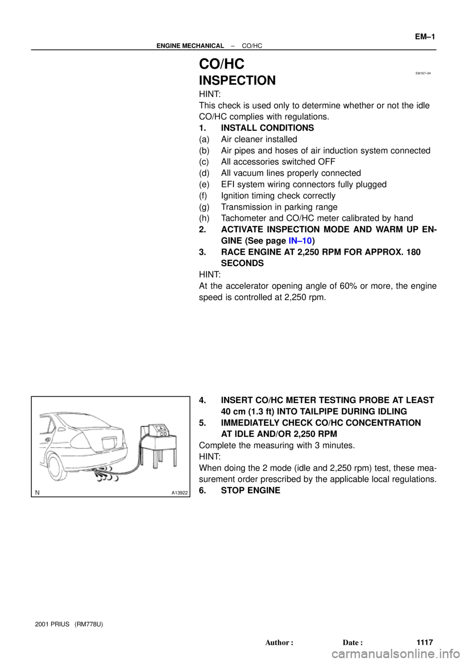
4. INSERT CO/HC METER TESTING PROBE AT LEAST
40 cm (1.3 ft) INTO TAILPIPE DURING IDLING
5. IMMEDIATELY CHECK CO/HC CONCENTRATION
AT IDLE AND/OR 2,250 RPM
Complete the measuring with 3 minutes.
HINT:
When doing the 2 mode (idle and 2,250 rpm) test, these mea-
surement order prescribed by the applicable local regulations.
6. STOP ENGINE
Page 1465 of 1943

EM±2
± ENGINE MECHANICALCO/HC
111 8 Author�: Date�:
2001 PRIUS (RM778U)
If the CO/HC concentration does not comply with regulations,
troubleshoot in the order given below.
�Check heated oxygen sensor operation.
(See page DI±44)
�See the table below for possible causes, and then inspect
and correct the applicable causes if necessary.
COHCProblemsCauses
NormalHighRough idle1. Faulty ignitions:
�Incorrect timing
�Fouled, shorted or improperly gapped plugs
�Open or crossed high±tension cords
2. Incorrect valve clearance
3. Leaky intake and exhaust valves
4. Leaky cylinders
LowHighRough idle
(Fluctuating HC reading)1. Vacuum leaks:
�PCV hoses
�Intake manifold
�Throttle body
2. Lean mixture causing misfire
HighHighRough idle
(Black smoke from exhaust)1. Restricted air filter
2. Plugged PCV valve
3. Faulty EFI systems:
�Faulty pressure regulator
�Defective water temperature sensor
�Defective air flow meter
�Faulty ECM
�Faulty injectors
�Faulty throttle position sensor
NormalHigh1. Faulty HCAC:
�Faulty VSV
�Faulty actuator
Page 1468 of 1943
EM169±02
A11244
A11245
Timing Marks
A11218
1
3
21
3
2
11
A11219
3
2
3
2
44
44
± ENGINE MECHANICALVALVE CLEARANCE
EM±5
1121 Author�: Date�:
2001 PRIUS (RM778U)
VALVE CLEARANCE
ADJUSTMENT
HINT:
Inspect and adjust the valve clearance when the engine is cold.
1. REMOVE CYLINDER HEAD COVER
(See page EM±15)
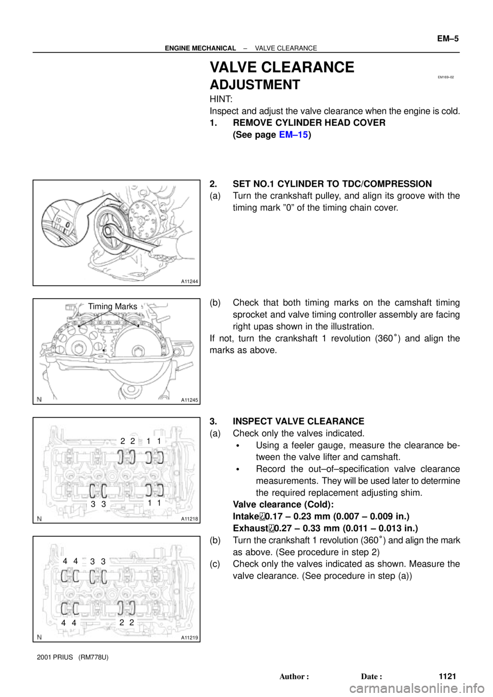
2. SET NO.1 CYLINDER TO TDC/COMPRESSION
(a) Turn the crankshaft pulley, and align its groove with the
timing mark º0º of the timing chain cover.
(b) Check that both timing marks on the camshaft timing
sprocket and valve timing controller assembly are facing
right upas shown in the illustration.
If not, turn the crankshaft 1 revolution (360°) and align the
marks as above.
3. INSPECT VALVE CLEARANCE
(a) Check only the valves indicated.
�Using a feeler gauge, measure the clearance be-
tween the valve lifter and camshaft.
�Record the out±of±specification valve clearance
measurements. They will be used later to determine
the required replacement adjusting shim.
Valve clearance (Cold):
Intake
0.17 ± 0.23 mm (0.007 ± 0.009 in.)
Exhaust
0.27 ± 0.33 mm (0.011 ± 0.013 in.)
(b) Turn the crankshaft 1 revolution (360°) and align the mark
as above. (See procedure in step 2)
(c) Check only the valves indicated as shown. Measure the
valve clearance. (See procedure in step (a))
Page 1473 of 1943
A11246
A11245
Timing Marks
A11252
Matchmarks
EM±10
± ENGINE MECHANICALVALVE CLEARANCE
1126 Author�: Date�:
2001 PRIUS (RM778U)
(l) Reinstall the valve lifters (See page EM±43).
(m) Align the crankshaft pulley groove with the timing mark º0º
of the timing chain cover.
(n) Hold the timing chain, and place the exhaust camshaft
and timing sprocket assembly.
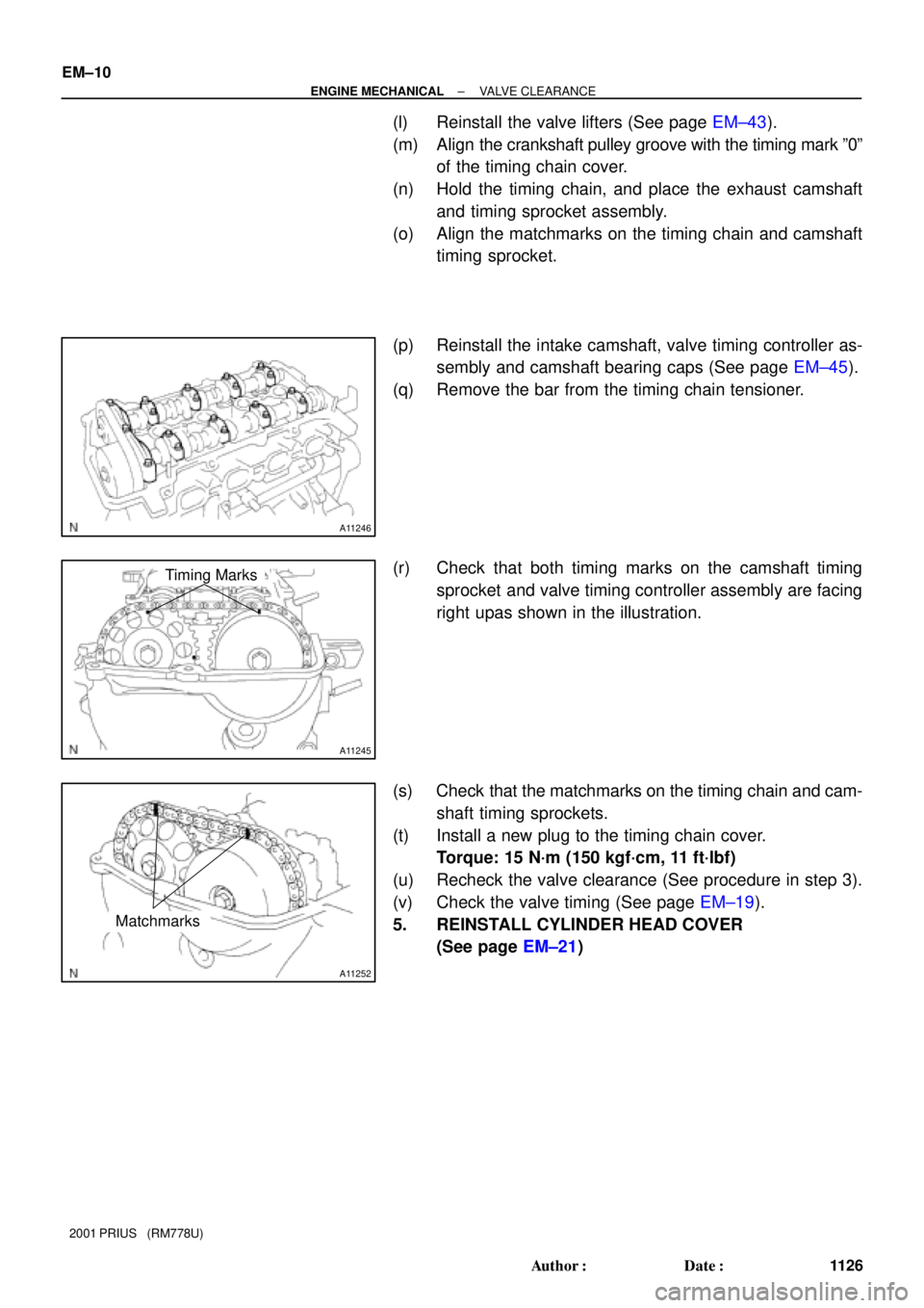
(o) Align the matchmarks on the timing chain and camshaft
timing sprocket.
(p) Reinstall the intake camshaft, valve timing controller as-
sembly and camshaft bearing caps (See page EM±45).
(q) Remove the bar from the timing chain tensioner.
(r) Check that both timing marks on the camshaft timing
sprocket and valve timing controller assembly are facing
right upas shown in the illustration.
(s) Check that the matchmarks on the timing chain and cam-
shaft timing sprockets.
(t) Install a new plug to the timing chain cover.
Torque: 15 N´m (150 kgf´cm, 11 ft´lbf)
(u) Recheck the valve clearance (See procedure in step 3).
(v) Check the valve timing (See page EM±19).
5. REINSTALL CYLINDER HEAD COVER
(See page EM±21)
Page 1478 of 1943
A11245
Timing Marks
A11253
SST
SST
A11254
SST
A11258
A11255
± ENGINE MECHANICALTIMING CHAIN
EM±17
2001 PRIUS (RM778U)
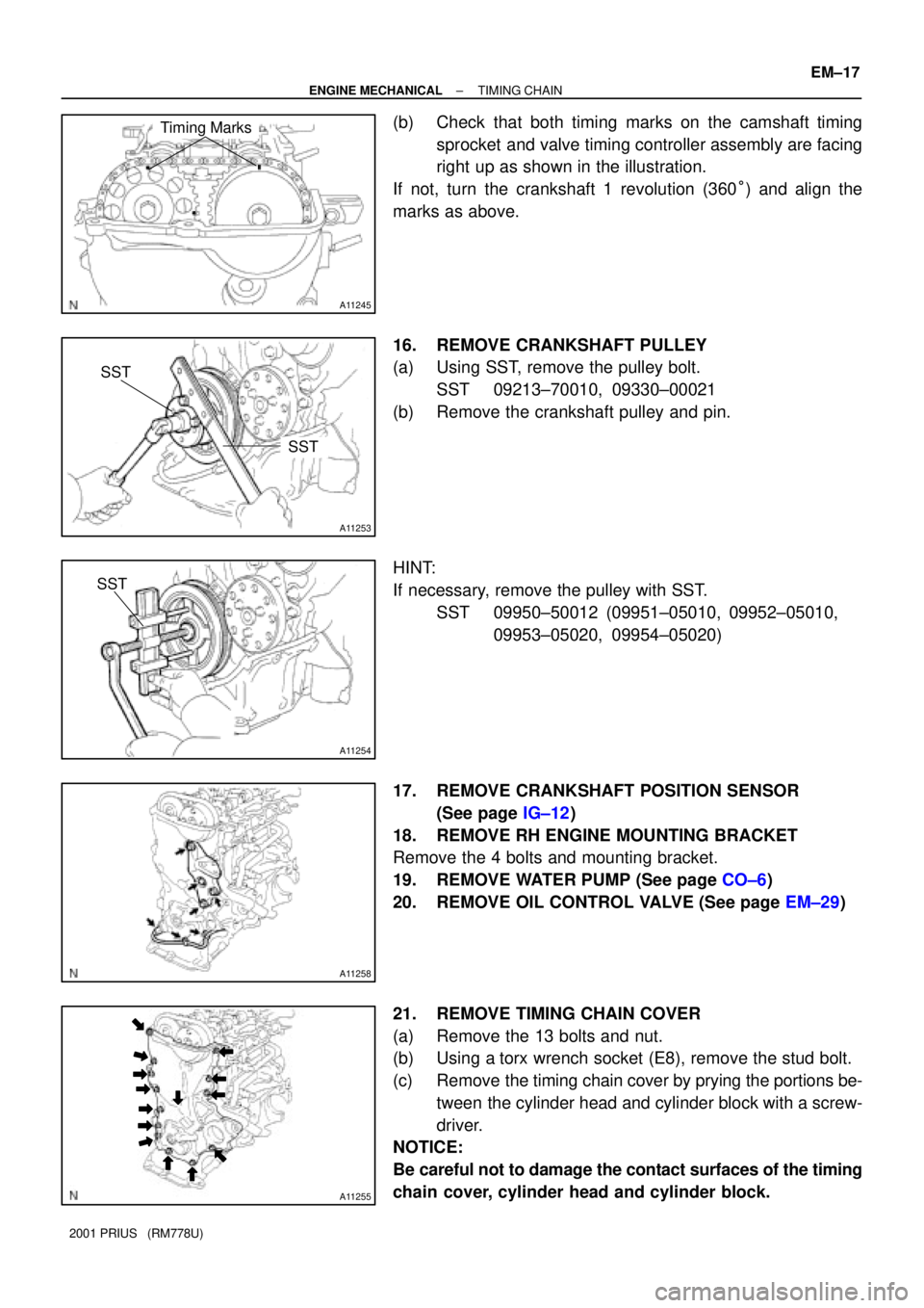
(b) Check that both timing marks on the camshaft timing
sprocket and valve timing controller assembly are facing
right up as shown in the illustration.
If not, turn the crankshaft 1 revolution (360°) and align the
marks as above.
16. REMOVE CRANKSHAFT PULLEY
(a) Using SST, remove the pulley bolt.
SST 09213±70010, 09330±00021
(b) Remove the crankshaft pulley and pin.
HINT:
If necessary, remove the pulley with SST.
SST 09950±50012 (09951±05010, 09952±05010,
09953±05020, 09954±05020)
17. REMOVE CRANKSHAFT POSITION SENSOR
(See page IG±12)
18. REMOVE RH ENGINE MOUNTING BRACKET
Remove the 4 bolts and mounting bracket.
19. REMOVE WATER PUMP (See page CO±6)
20. REMOVE OIL CONTROL VALVE (See page EM±29)
21. REMOVE TIMING CHAIN COVER
(a) Remove the 13 bolts and nut.
(b) Using a torx wrench socket (E8), remove the stud bolt.
(c) Remove the timing chain cover by prying the portions be-
tween the cylinder head and cylinder block with a screw-
driver.
NOTICE:
Be careful not to damage the contact surfaces of the timing
chain cover, cylinder head and cylinder block.
Page 1480 of 1943
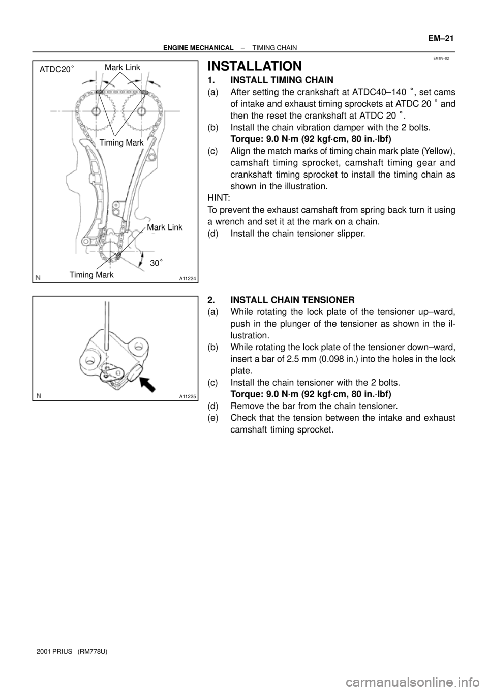
EM1IV±02
A11224
ATDC20°Mark Link
Timing Mark
30°
Timing Mark
Mark Link
A11225
± ENGINE MECHANICALTIMING CHAIN
EM±21
2001 PRIUS (RM778U)
INSTALLATION
1. INSTALL TIMING CHAIN
(a) After setting the crankshaft at ATDC40±140 °, set cams
of intake and exhaust timing sprockets at ATDC 20 ° and
then the reset the crankshaft at ATDC 20 °.
(b) Install the chain vibration damper with the 2 bolts.
Torque: 9.0 N´m (92 kgf´cm, 80 in.´lbf)
(c) Align the match marks of timing chain mark plate (Yellow),
camshaft timing sprocket, camshaft timing gear and
crankshaft timing sprocket to install the timing chain as
shown in the illustration.
HINT:
To prevent the exhaust camshaft from spring back turn it using
a wrench and set it at the mark on a chain.
(d) Install the chain tensioner slipper.
2. INSTALL CHAIN TENSIONER
(a) While rotating the lock plate of the tensioner up±ward,
push in the plunger of the tensioner as shown in the il-
lustration.
(b) While rotating the lock plate of the tensioner down±ward,
insert a bar of 2.5 mm (0.098 in.) into the holes in the lock
plate.
(c) Install the chain tensioner with the 2 bolts.
Torque: 9.0 N´m (92 kgf´cm, 80 in.´lbf)
(d) Remove the bar from the chain tensioner.
(e) Check that the tension between the intake and exhaust
camshaft timing sprocket.