Page 1185 of 1943

AB0119H03354
H03364H08348
Airbag
Sensor
Assembly Front Airbag
Sensor (RH)
(+)
+SR
(±)
±SR
ON
Engine Room No. 2
Wire Harness
u"
H03354H03362H08349
Airbag
Sensor
Assembly Front Airbag
Sensor (RH)
(+)+SR
(±)±SR Engine Room No. 2
Wire Harness
± DIAGNOSTICSSUPPLEMENTAL RESTRAINT SYSTEM
DI±623
2001 PRIUS (RM778U)
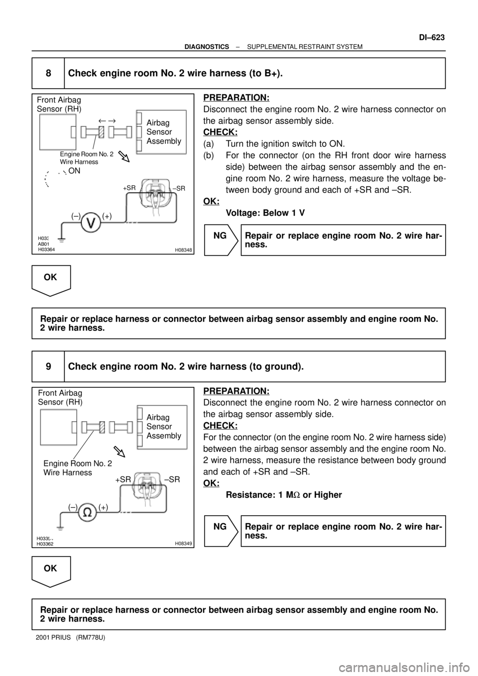
8 Check engine room No. 2 wire harness (to B+).
PREPARATION:
Disconnect the engine room No. 2 wire harness connector on
the airbag sensor assembly side.
CHECK:
(a) Turn the ignition switch to ON.
(b) For the connector (on the RH front door wire harness
side) between the airbag sensor assembly and the en-
gine room No. 2 wire harness, measure the voltage be-
tween body ground and each of +SR and ±SR.
OK:
Voltage: Below 1 V
NG Repair or replace engine room No. 2 wire har-
ness.
OK
Repair or replace harness or connector between airbag sensor assembly and engine room No.
2 wire harness.
9 Check engine room No. 2 wire harness (to ground).
PREPARATION:
Disconnect the engine room No. 2 wire harness connector on
the airbag sensor assembly side.
CHECK:
For the connector (on the engine room No. 2 wire harness side)
between the airbag sensor assembly and the engine room No.
2 wire harness, measure the resistance between body ground
and each of +SR and ±SR.
OK:
Resistance: 1 MW or Higher
NG Repair or replace engine room No. 2 wire har-
ness.
OK
Repair or replace harness or connector between airbag sensor assembly and engine room No.
2 wire harness.
Page 1186 of 1943
H03354H09507H08351
Airbag
Sensor
Assembly
Front Airbag
Sensor (RH)
(±) +SR
±SR
Engine Room No. 2
Wire Harness
(+)
u "
DI±624
± DIAGNOSTICSSUPPLEMENTAL RESTRAINT SYSTEM
2001 PRIUS (RM778U)
10 Check engine room No. 2 wire harness.
PREPARATION:
Disconnect the engine room No. 2 wire harness connector on
the airbag sensor assembly side.
CHECK:
For the connector (on the engine room No. 2 wire harness side)
between the airbag sensor assembly and the engine room No.
2 wire harness, measure the resistance between +SR and ±SR.
OK:
Resistance: 1 MW or Higher
NG Repair or replace engine room No. 2 wire har-
ness.
OK
Repair or replace harness or connector between airbag sensor assembly and engine room No.
2 wire harness.
Page 1187 of 1943
H03352H09507H03360H08350
Airbag
Sensor
Assembly Front Airbag
Sensor (RH)
(+) +SR
(±)±SR
Engine Room No. 2
Wire Harness
+SR
±SR
u "
± DIAGNOSTICSSUPPLEMENTAL RESTRAINT SYSTEM
DI±625
2001 PRIUS (RM778U)
11 Check engine room No. 2 wire harness.
PREPARATION:
(a) Disconnect the engine room No. 2 wire harness connec-
tor on the airbag sensor assembly side.
(b) Using a service wire, connect +SR and ±SR of the con-
nector (on the engine room No. 2 wire harness side) be-
tween the engine room No. 2 wire harness and the front
airbag sensor (RH).
CHECK:
For the connector (on the engine room No. 2 wire harness side)
between the airbag sensor assembly and the engine room No.
2 wire harness, measure the resistance between +SR and ±SR.
OK:
Resistance: Below 1 W
NG Repair or replace engine room No. 2 wire har-
ness.
OK
Repair or replace harness or connector between airbag sensor assembly and engine room No.
2 wire harness.
Page 1193 of 1943

H03354H16253H16297
Airbag
Sensor
Assembly Front Airbag
Sensor (LH)
(+)
+SL
(±)
±SL
ON
Engine Room Main
Wire Harness
u"
H03354H16252H16298
Airbag
Sensor
Assembly Front Airbag
Sensor (LH)
(+)+SL
(±)±SL Engine Room Main
Wire Harness
± DIAGNOSTICSSUPPLEMENTAL RESTRAINT SYSTEM
DI±631
2001 PRIUS (RM778U)
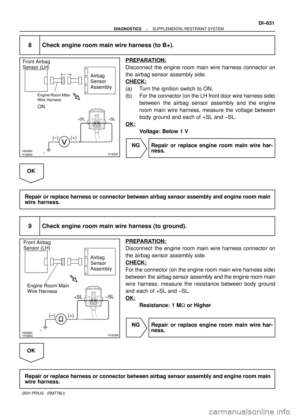
8 Check engine room main wire harness (to B+).
PREPARATION:
Disconnect the engine room main wire harness connector on
the airbag sensor assembly side.
CHECK:
(a) Turn the ignition switch to ON.
(b) For the connector (on the LH front door wire harness side)
between the airbag sensor assembly and the engine
room main wire harness, measure the voltage between
body ground and each of +SL and ±SL.
OK:
Voltage: Below 1 V
NG Repair or replace engine room main wire har-
ness.
OK
Repair or replace harness or connector between airbag sensor assembly and engine room main
wire harness.
9 Check engine room main wire harness (to ground).
PREPARATION:
Disconnect the engine room main wire harness connector on
the airbag sensor assembly side.
CHECK:
For the connector (on the engine room main wire harness side)
between the airbag sensor assembly and the engine room main
wire harness, measure the resistance between body ground
and each of +SL and ±SL.
OK:
Resistance: 1 MW or Higher
NG Repair or replace engine room main wire har-
ness.
OK
Repair or replace harness or connector between airbag sensor assembly and engine room main
wire harness.
Page 1194 of 1943
H03354H16251H16299
Airbag
Sensor
Assembly
Front Airbag
Sensor (LH)
(±) +SL
±SL
Engine Room Main
Wire Harness
(+)
u "
DI±632
± DIAGNOSTICSSUPPLEMENTAL RESTRAINT SYSTEM
2001 PRIUS (RM778U)
10 Check engine room main wire harness.
PREPARATION:
Disconnect the engine room main wire harness connector on
the airbag sensor assembly side.
CHECK:
For the connector (on the engine room main wire harness side)
between the airbag sensor assembly and the engine room main
wire harness, measure the resistance between +SL and ±SL.
OK:
Resistance: 1 MW or Higher
NG Repair or replace engine room main wire har-
ness.
OK
Repair or replace harness or connector between airbag sensor assembly and engine room main
wire harness.
Page 1195 of 1943
H03352H16251H03360H16300
Airbag
Sensor
Assembly Front Airbag
Sensor (LH)
(+) +SL
(±)±SL
Engine Room Main
Wire Harness
+SL
±SL
u "
± DIAGNOSTICSSUPPLEMENTAL RESTRAINT SYSTEM
DI±633
2001 PRIUS (RM778U)
11 Check engine room main wire harness.
PREPARATION:
(a) Disconnect the engine room main wire harness connector
on the airbag sensor assembly side.
(b) Using a service wire, connect +SL and ±SL of the connec-
tor (on the engine room main wire harness side) between
the engine room main wire harness and the front airbag
sensor (LH).
CHECK:
For the connector (on the engine room main wire harness side)
between the airbag sensor assembly and the engine room main
wire harness, measure the resistance between +SL and ±SL.
OK:
Resistance: Below 1 W
NG Repair or replace engine room main wire har-
ness.
OK
Repair or replace harness or connector between airbag sensor assembly and engine room main
wire harness.
Page 1218 of 1943
DI7XP±01
± DIAGNOSTICSCOMBINATION METER SYSTEM
DI±669
2001 PRIUS (RM778U)
PRE±CHECK
1. BEFORE CHECK
Since a trouble symptom may result from multiple causes, check not only the part where a user complains
of but also the following items in order to be sure no other trouble is identified.
�Fuse related parts
�Wire harness related parts
�Valve related parts
NOTICE:
�Setting the ignition switch to START temporarily stops all meter operation, however, this is not
an error.
�When replacing the combination meter ECU, carefully avoid any contact with the IC.
�Removing a battery terminal during engine operation may cause a reversed current and lead
to malfunction.
�When disconnecting any connector or terminal, be sure to disconnect the battery terminal.
Page 1219 of 1943

Flashing pattern No.1
Flashing pattern No.2
0.6 sec. 0.6 sec.
0.3 sec. 0.3 sec. 1.2 sec. ON
OFF ON
OFF
0.3 sec.
DI±670
± DIAGNOSTICSCOMBINATION METER SYSTEM
2001 PRIUS (RM778U)
2. FUEL GAUGE DIAGNOSIS CHECK
(a) Fuel emergency display
HINT:
If FR voltage input to the fuel sender gauge is abnormal (4.8 V or more, or 0.06 V or less) due to any error,
an emergency will be displayed.
(b) Display:
Immediately after the ignition switch is ON, all of the segments flash.
Diagnosis displayTrouble ItemPlausible Cause
All segments flashing
(Flashing pattern No. 1)
Cycle: 1.2 sec
Duty: 50 %Multiple communication errorCommunication is cut off.
4. Body ECU faulty
5. Engine ECU faulty
6. Open or short in wire harness for communica-
tion
HINT:
Referring to the attached reference material 1 or
2, specify the main cause
All segments flashing
(Flashing pattern No. 2)
(300 msec. ON, 300 msec OFF) x 2 + 1.2
sec. OFFSender gauge related trouble1. Sender gauge faulty
2. Open or short in wire harness
Display segments and ºEº flashing.
(Flashing pattern No. 1)
Cycle: 1.2 sec
Duty: 50 %Temperature sensor (located in the tank) related
trouble1. Temperature sensor faulty
2. Open or short in wire harness
Display segments and ºEº flashing.
(Flashing pattern No. 2)
(300 msec. ON, 300 msec. OFF) x 2 + 1.2
sec. OFFIndication sensor (located in the meter ) trouble1. Combination meter faulty
Segment No. 1 flashing
(Flashing pattern No. 1)
Cycle: 1.2 sec
Duty: 50 %This does not mean any failure.
When a battery is connected, it continues flash-
ing until the volume is confirmed.This occurs when the battery is turned ON.
HINT:
Low fuel warning: Cycle: 0.6 sec.;
Duty: 50 %