Page 928 of 1943

± DIAGNOSTICSHV BATTERY CONTROL SYSTEM
DI±345
2001 PRIUS (RM778U)
INSPECTION PROCEDURE
1 Are there any other codes (besides DTC P3030) being outputs?
YES Go to relevant DTC chart.
NO
2 Check voltage of battery block 1 to 19.
CHECK:
Connecting a TOYOTA hand±held tester, check the ECU data.
HINT:
Nineteen blocks of battery modules are arranged in the order of 1 to 19 from the battery ECU side.
OK:
Standard voltage: 2V or more
OK Go to step 4.
NG
3 Check that the HV battery blocks voltage swings at stall test.
PREPARATION:
(a) To ensure safety, conduct this test in a wide, clear level area which provides good traction.
(b) Turn ON the ºREADYº light.
(c) Warm up the engine and turn off the A/C switch.
(d) Fully apply the parking brake and chock the 4 wheels.
(e) Connect a TOYOTA hand±held tester to DLC3 and select HV BATTERY and then CURRENT DATA
to show ºBAT BLOCK MIN Vº and ºBAT BLOCK MAX Vº on the TOYOTA hand±held tester.
CHECK:
(a) Keep your left foot pressed firmly on the brake pedal and shift into the R position.
(b) Stepping on the brake pedal, release the accelerator pedal during the engine moving and step on the
accelerator pedal during the engine stopping.
(c) Continue STEP (b) for more than 20 min. and monitor the swing and the difference of the voltage be-
tween the data MAX V and MIN V.
Page 929 of 1943
A16880
The difference of the voltage
between the date VMAX and VMIN
SwingVMAX data
The engine start Test startTime
Voltage
Swing
Swing
SwingVMIN data
DI±346
± DIAGNOSTICSHV BATTERY CONTROL SYSTEM
2001 PRIUS (RM778U) 4/27/01
OK:
Standard voltage swing: 2 V or more
NG Replace the battery ECU (See page IN±41).
OK
4 Check tightening condition of busbar module of block and correct if necessary.
OK:
The nut is not loosened.
Torque: 6 N´m (61 kgf´cm, 4.4 ft´lbf)
NG Tighten the nut.
OK
5 Check if busbar module connector is properly connected.
NG Connect properly, repair or replace.
OK
Page 934 of 1943
A14084
Engine Room J/B
FAN Fuse
DI±352
± DIAGNOSTICSHV BATTERY CONTROL SYSTEM
2001 PRIUS (RM778U)
INSPECTION PROCEDURE
1 Check FAN fuse of engine room J/B.
PREPARATION:
Remove the FAN fuse from the engine room J/B.
CHECK:
Check the continuity of the FAN fuse.
OK:
Continuity
NG Check for short in all harness and components
connected to FAN fuse. Check that the motor is
not locked. If locked, replace the motor.
OK
2 Check blower fan relay (See page HV±35).
NG Replace the blower fan relay.
OK
3 Check blower motor operation.
PREPARATION:
Remove the blower motor (See page HV±32).
CHECK:
Apply battery voltage to the power supply terminal of the motor, and check the fan rotation.
OK:
The fan rotates normally.
NG Replace the blower motor.
OK
Replace battery blower motor controller.
Page 940 of 1943

F12396
TOYOTA
Hand±held Tester
DLC3
F09750
DLC3Tc
Ts
CG
BR3904
0.13 sec. 0.13 sec.
ON
OFF DI±360
± DIAGNOSTICSANTI±LOCK BRAKE SYSTEM WITH EBD & RBS
2001 PRIUS (RM778U)
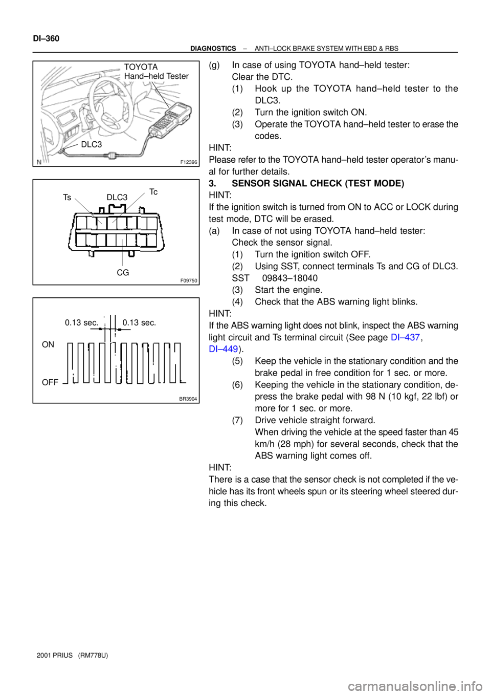
(g) In case of using TOYOTA hand±held tester:
Clear the DTC.
(1) Hook up the TOYOTA hand±held tester to the
DLC3.
(2) Turn the ignition switch ON.
(3) Operate the TOYOTA hand±held tester to erase the
codes.
HINT:
Please refer to the TOYOTA hand±held tester operator's manu-
al for further details.
3. SENSOR SIGNAL CHECK (TEST MODE)
HINT:
If the ignition switch is turned from ON to ACC or LOCK during
test mode, DTC will be erased.
(a) In case of not using TOYOTA hand±held tester:
Check the sensor signal.
(1) Turn the ignition switch OFF.
(2) Using SST, connect terminals Ts and CG of DLC3.
SST 09843±18040
(3) Start the engine.
(4) Check that the ABS warning light blinks.
HINT:
If the ABS warning light does not blink, inspect the ABS warning
light circuit and Ts terminal circuit (See page DI±437,
DI±449).
(5) Keep the vehicle in the stationary condition and the
brake pedal in free condition for 1 sec. or more.
(6) Keeping the vehicle in the stationary condition, de-
press the brake pedal with 98 N (10 kgf, 22 lbf) or
more for 1 sec. or more.
(7) Drive vehicle straight forward.
When driving the vehicle at the speed faster than 45
km/h (28 mph) for several seconds, check that the
ABS warning light comes off.
HINT:
There is a case that the sensor check is not completed if the ve-
hicle has its front wheels spun or its steering wheel steered dur-
ing this check.
Page 959 of 1943

F12672
Brake ECU
AST Engine Room R/B No. 3
ABS Solenoid
Relay 3 W
DC/DCW±R
Y±B
R1+
SR 14
W±BBrake Actuator FL
Block
No. 11
1
1ABS No. 1
F10
MAIN
BatteryA
A B±G
J7
J/CB±L
BS7
21
1
B±O 3
Engine Room
R/B No. 3
FL
Block
No. 2F13
A
IEJ1
J/C W±B
B10
B13 B11 B1
Brake
ECU 3
3 3
3 33
64
B2
B3 AST6 6
Y±B
19 2 1
R
± DIAGNOSTICSANTI±LOCK BRAKE SYSTEM WITH EBD & RBS
DI±381
2001 PRIUS (RM778U)
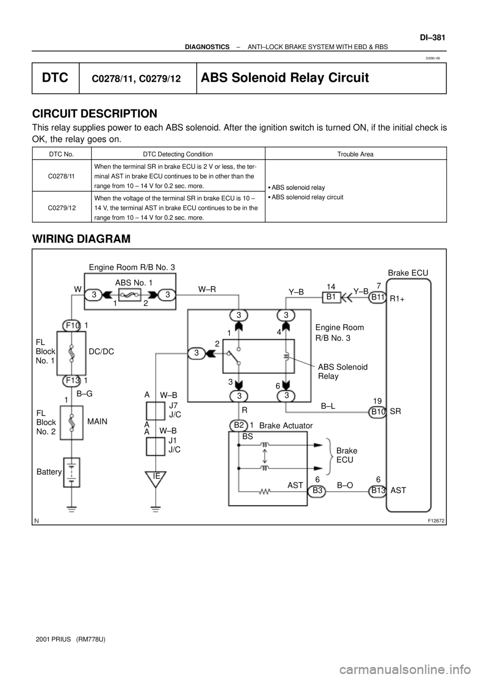
DTCC0278/11, C0279/12ABS Solenoid Relay Circuit
CIRCUIT DESCRIPTION
This relay supplies power to each ABS solenoid. After the ignition switch is turned ON, if the initial check is
OK, the relay goes on.
DTC No.DTC Detecting ConditionTrouble Area
C0278/11
When the terminal SR in brake ECU is 2 V or less, the ter-
minal AST in brake ECU continues to be in other than the
range from 10 ± 14 V for 0.2 sec. more.
�ABS solenoid relay
C0279/12
When the voltage of the terminal SR in brake ECU is 10 ±
14 V, the terminal AST in brake ECU continues to be in the
range from 10 ± 14 V for 0.2 sec. more.
�ABS solenoid relay
�ABS solenoid relay circuit
WIRING DIAGRAM
DI290±08
Page 960 of 1943

F12662
LOCK
1 2
Engine Room R/B No. 3
DI±382
± DIAGNOSTICSANTI±LOCK BRAKE SYSTEM WITH EBD & RBS
2001 PRIUS (RM778U)
INSPECTION PROCEDURE
HINT:
Start the inspection from step 1 in case of using the TOYOTA hand±held tester and start from step 2 in case
of not using the TOYOTA hand±held tester.
1 Check ABS solenoid relay operation.
PREPARATION:
(a) Connect the TOYOTA hand±held tester to the DLC3.
(b) Turn the ignition switch ON, and push the TOYOTA hand±held tester main switch ON.
(c) Select the ACTIVE TEST mode on the TOYOTA hand±held tester.
CHECK:
Check the operation sound of the ABS solenoid relay when operating it with the TOYOTA hand±held tester.
OK:
The operation sound of the ABS solenoid relay should be heard.
OK Go to step 4.
NG
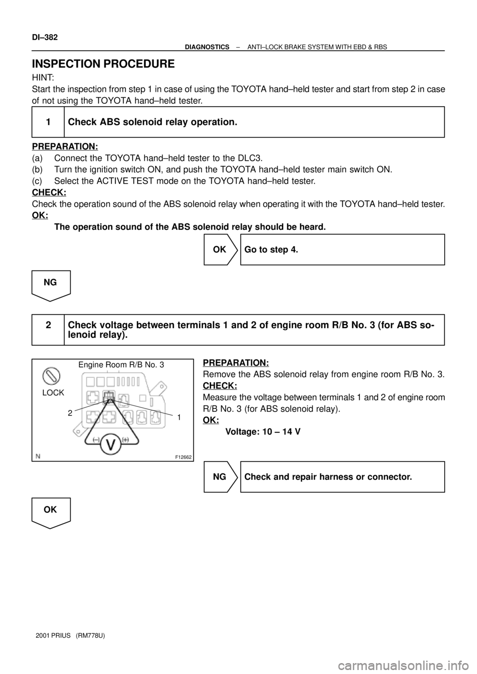
2 Check voltage between terminals 1 and 2 of engine room R/B No. 3 (for ABS so-
lenoid relay).
PREPARATION:
Remove the ABS solenoid relay from engine room R/B No. 3.
CHECK:
Measure the voltage between terminals 1 and 2 of engine room
R/B No. 3 (for ABS solenoid relay).
OK:
Voltage: 10 ± 14 V
NG Check and repair harness or connector.
OK
Page 962 of 1943
F12443
ABS Solenoid
RelayEngine Room R/B
No. 3
Brake
Actuator
Brake ECU
ASTBS3
ASTAST
DI±384
± DIAGNOSTICSANTI±LOCK BRAKE SYSTEM WITH EBD & RBS
2001 PRIUS (RM778U)
4 Check continuity between terminals 3 of engine room R/B No. 3 (for ABS sole-
noid relay) and terminal AST of brake ECU.
CHECK:
Check continuity between terminal 3 of engine room R/B No. 3
(for ABS solenoid relay) and terminal AST of brake ECU.
OK:
Continuity
HINT:
There is a resistance of approx. 33 W between terminals BS and
AST of the brake actuator.
NG Repair or replace harness or brake actuator.
OK
5 Check for open and short circuit in harness and connector between ABS sole-
noid relay and brake ECU (See page IN±41).
NG Repair or replace harness or connector.
OK
If the same code is still output after the DTC is deleted, check the contact condition of each con-
nection. If the connections are normal, the ECU may be defective.
Page 970 of 1943
F12445
Engine Room R/B No. 3
ABS No. 4
± DIAGNOSTICSANTI±LOCK BRAKE SYSTEM WITH EBD & RBS
DI±393
2001 PRIUS (RM778U)
INSPECTION PROCEDURE
1 Check ABS No. 4 fuse.
PREPARATION:
Remove the ABS No. 4 fuse from engine room R/B No. 3.
CHECK:
Check continuity of ABS No. 4 fuse.
OK:
Continuity
NG Check for short circuit in all the harness and
components connected to ABS No. 4 fuse (See
attached wiring diagram).
OK
2 Check battery positive voltage.
OK:
Voltage: 10 ± 14 V
NG Check and repair the charging system (See
page HV±39).
OK