Page 996 of 1943
F00044
1
2
3 4
(+) (±) Continuity1 2
3 4
1
2
3 4 Open
Continuity
± DIAGNOSTICSANTI±LOCK BRAKE SYSTEM WITH EBD & RBS
DI±419
2001 PRIUS (RM778U)
7 Check hydro motor relay No. 1 and No. 2.
PREPARATION:
Remove the hydro motor relay No. 1 and No. 2 from the engine
room R/B No. 2.
CHECK:
Check continuity between each pair of terminal of motor relay.
OK:
Terminals 3 and 4Continuity
(Reference value *)
Terminals 1 and 2Open
*
Reference value:
Hydro motor relay No. 1 62 W
Hydro motor relay No. 2 54 W
CHECK:
(a) Apply battery positive voltage between terminals 3 and 4.
(b) Check continuity between terminals.
OK:
Terminals 1 and 2Continuity
NG Replace hydro motor relay.
OK
8 Check for short circuit in harness and connector between hydro motor relay No.
1, No. 2 and brake ECU (See page IN±41).
NG Repair or replace harness or connector.
OK
Check and replace brake ECU.
Page 1001 of 1943
F12663
(+) (±)
Engine Room R/B No. 2LOCK
1
1
F00044
1
2
3 4
(+) (±) Continuity1 2
3 4
1
2
3 4 Open
Continuity
DI±424
± DIAGNOSTICSANTI±LOCK BRAKE SYSTEM WITH EBD & RBS
2001 PRIUS (RM778U)
3 Check voltage between terminal 1 of engine room R/B No. 2 (for hydro motor re-
lays) and body ground.
PREPARATION:
Remove the hydro motor relay No. 1 and No. 2 from the engine
room R/B No. 2.
CHECK:
Measure voltage between terminal 1 of engine room R/B No. 2
(for hydro motor relays) and body ground.
OK:
Voltage: 10 ± 14 V
NG Check and repair harness or connector.
OK
4 Check hydro motor relay.
CHECK:
Check continuity between each pair of terminal of motor relay.
OK:
Terminals 3 and 4Continuity
(Reference value *)
Terminals 1 and 2Open
* Reference value:
Hydro motor relay No. 1 62 W
Hydro motor relay No. 2 54 W
CHECK:
(a) Apply battery positive voltage between terminals 3 and 4.
(b) Check continuity between terminals.
OK:
Terminals 1 and 2Continuity
NG Replace hydro motor relay.
OK
Page 1002 of 1943
F12412
Relay
No. 1
2
Brake ECU
MTT Motor
RelayRelay
No. 2 Engine Room R/B No. 2
MTT
2
BM1BM2
± DIAGNOSTICSANTI±LOCK BRAKE SYSTEM WITH EBD & RBS
DI±425
2001 PRIUS (RM778U)
5 Check continuity between each terminal 2 of engine room R/B No. 2 (for hydro
motor relay) and terminal MTT of brake ECU.
CHECK:
(a) Check continuity betwee terminal 2 of engine room R/B
No. 2 (for hydro motor relay No. 1) and terminal MTT of
brake ECU.
(b) Check continuity between terminal 2 of engine room R/B
No. 2 (for hydro motor relay No. 2) and terminal MTT of
brake ECU.
OK:
Continuity
HINT:
There is resistance of 33 ± 3 W between terminals BM1or BM2
and MTT of the hydraulic brake booster.
NG Repair or replace harness, connector or hy-
draulic brake booster.
OK
6 Check for open and short circuit in harness and connector between hydro motor
relay No. 1 and No. 2 and brake ECU (See page IN±41).
NG Repair or replace harness or connector.
OK
Check and replace brake ECU.
Page 1007 of 1943

F12682
High Pressure
Switch
H5
H6 Hydraulic Brake Booster
W±B W±B W±B 5
A 1
IE GR
J1
J/C Y±R 4
49 B1011Brake ECU
PL PH
B13 H5
H6J7
J/C
A A PL PH
PLG PHG
Low Pressure
SwitchW±B
DI±430
± DIAGNOSTICSANTI±LOCK BRAKE SYSTEM WITH EBD & RBS
2001 PRIUS (RM778U)
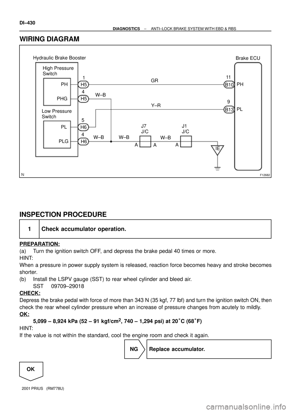
WIRING DIAGRAM
INSPECTION PROCEDURE
1 Check accumulator operation.
PREPARATION:
(a) Turn the ignition switch OFF, and depress the brake pedal 40 times or more.
HINT:
When a pressure in power supply system is released, reaction force becomes heavy and stroke becomes
shorter.
(b) Install the LSPV gauge (SST) to rear wheel cylinder and bleed air.
SST 09709±29018
CHECK:
Depress the brake pedal with force of more than 343 N (35 kgf, 77 lbf) and turn the ignition switch ON, then
check the rear wheel cylinder pressure when an increase of pressure changes from acutely to mildly.
OK:
5,099 ± 8,924 kPa (52 ± 91 kgf/cm2, 740 ± 1,294 psi) at 20°C (68°F)
HINT:
If the value is not within the standard, cool the engine room and check it again.
NG Replace accumulator.
OK
Page 1020 of 1943

F00043
1 2 3
4 5 6
1 2 3
4 5 6
1 2 3
4
65 Open
Continuity
Continuity
Continuity
Open
(+)(±)
(+) (±)1 2 3
4 5 6 Continuity
DI±444
± DIAGNOSTICSANTI±LOCK BRAKE SYSTEM WITH EBD & RBS
2001 PRIUS (RM778U)
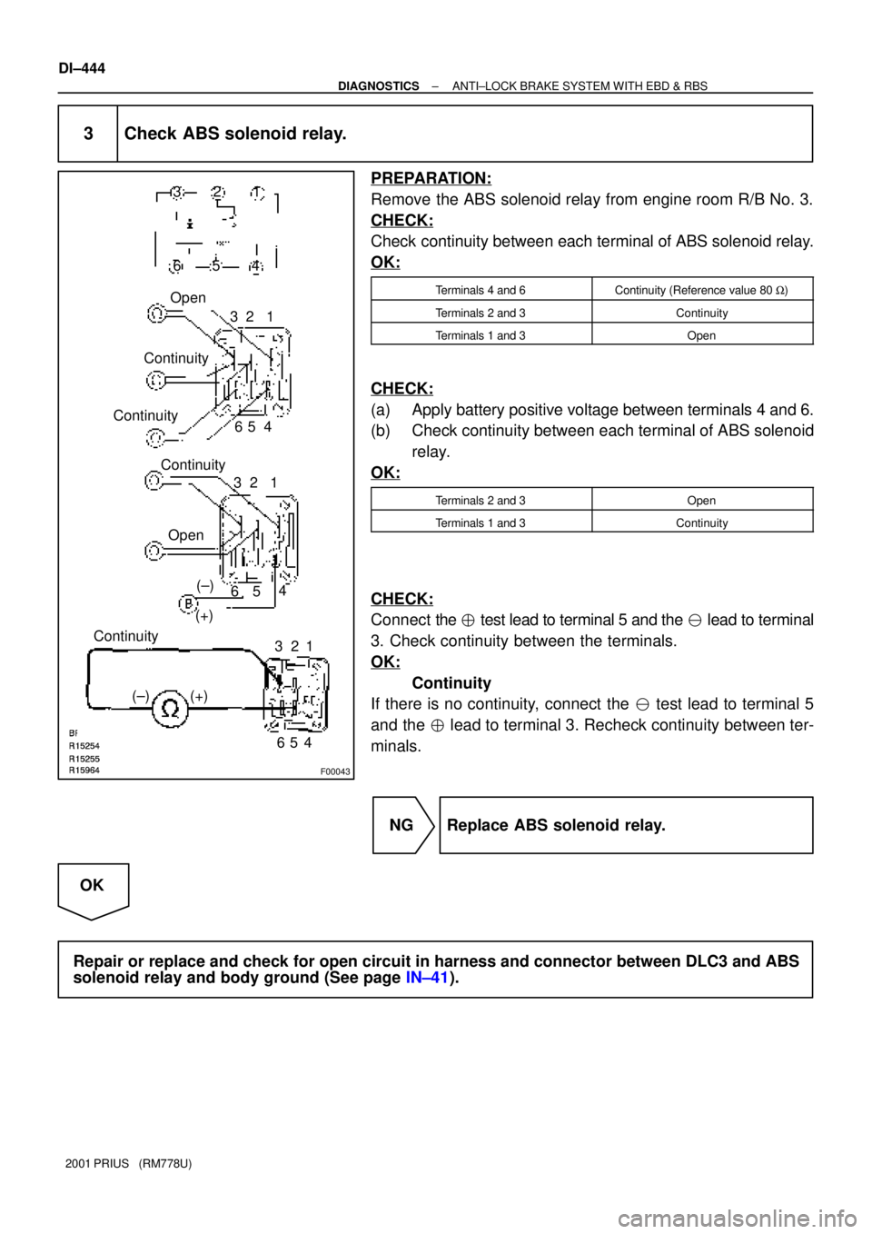
3 Check ABS solenoid relay.
PREPARATION:
Remove the ABS solenoid relay from engine room R/B No. 3.
CHECK:
Check continuity between each terminal of ABS solenoid relay.
OK:
Terminals 4 and 6Continuity (Reference value 80 W)
Terminals 2 and 3Continuity
Terminals 1 and 3Open
CHECK:
(a) Apply battery positive voltage between terminals 4 and 6.
(b) Check continuity between each terminal of ABS solenoid
relay.
OK:
Terminals 2 and 3Open
Terminals 1 and 3Continuity
CHECK:
Connect the � test lead to terminal 5 and the � lead to terminal
3. Check continuity between the terminals.
OK:
Continuity
If there is no continuity, connect the � test lead to terminal 5
and the � lead to terminal 3. Recheck continuity between ter-
minals.
NG Replace ABS solenoid relay.
OK
Repair or replace and check for open circuit in harness and connector between DLC3 and ABS
solenoid relay and body ground (See page IN±41).
Page 1054 of 1943
F12862
Engine Room
R/B No. 3
EMPS
Fuse
DI±486
± DIAGNOSTICSELECTRIC MOTOR POWER STEERING
2001 PRIUS (RM778U)
3 Check EMPS fuse.
PREPARATION:
5/18/01Remove the EMPS fuse from engine room R/B No. 3.
CHECK:
5/18/01Check continuity of EMPS fuse.
OK:
Continuity
NG Check for short circuit in harness and all com-
ponents connected to EMPS fuse (See attached
wiring diagram).
OK
Check for open and short circuit in harness and connector between EMPS ECU and battery
(See page IN±41).
Page 1056 of 1943
F12828
ON
RLY
PGND
F11788
5
13
2
Open
Continuity
5
2 1
3
5
2 1
3 Continuity
± DIAGNOSTICSELECTRIC MOTOR POWER STEERING
DI±489
2001 PRIUS (RM778U)
INSPECTION PROCEDURE
1 Check voltage between terminals RLY and PGND of EMPS ECU connector.
PREPARATION:
Remove the EMPS ECU with connectors still connected.
CHECK:
Turn the ignition switch ON and measure the voltage between
terminals RLY and PGND of EMPS ECU connector.
OK:
Voltage: 9 ± 14 V
OK Check or replace EMPS ECU.
NG
2 Check EMPS relay.
PREPARATION:
Remove the EMPS relay from the engine room R/B No. 3.
CHECK:
Check the continuity between each terminal of the EMPS relay.
OK:
Terminals 1 and 2Continuity (Reference value 80 W)
Terminals 3 and 5Open
CHECK:
(a) Apply battery positive voltage between terminals 1 and 2.
(b) Check the continuity between the terminals.
OK:
Terminals 3 and 5Continuity
Page 1061 of 1943
± DIAGNOSTICSELECTRIC MOTOR POWER STEERING
DI±495
2001 PRIUS (RM778U)
4 Check battery positive voltage.
PREPARATION:
Start the engine.
CHECK:
Check the battery positive voltage.
OK:
Voltage: 9 ± 14 V
NG Check and repair charging system.
OK
5 Check operation of PS warning light.
PREPARATION:
(a) Turn the ignition switch OFF.
(b) Disconnect the connector from the EMPS ECU.
(c) Turn the ignition switch ON.
CHECK:
Check the PS warning light goes OFF.
OK Check and replace EMPS ECU.
NG
Check for short circuit in harness and connector between multiinformation display and EMPS
ECU, multiinformation display and DLC3 (See page IN±41).