Page 893 of 1943
A14736
BatteryMAINB±G 1
1
F18 1 1
5
1
F132 3 2
2Engine Room J/B
W±B IK1 2
14
5
AM2 B±WB±W
B±W I15
Ignition SW W±R
6 711
IG2 AM2
Instrument Panel J/B
2C
1K 1A 2G9
1J
1B
B
F12IG2 Relay
Fusible Link
Block No. 1
Fusible Link
Block No. 2 1J
2G
2BW±R
13 3
IE AA AB±W
2
W±B W±B
W±BW3
Water
Pump
Motor
J1
J/C J7
J/C W±B DI±302
± DIAGNOSTICSHYBRID VEHICLE CONTROL SYSTEM
2001 PRIUS (RM778U)
DTC P3130 Inverter Cooling System Malfunction
CIRCUIT DESCRIPTION
The HV ECU checks the operation of the inverter water pump and detects malfunction.
HINT:
�When using an OBD scan tool other than TOYOTA hand±held tester, check all the steps.
�When using TOYOTA hand±held tester, confirm the information code and check it.
DTC P3130 ± Information code 346
INF. code.Detecting ConditionTrouble Area
346Water pump system malfunction
�Inverter water pump
�IG2 relay
�Wire harness
WIRING DIAGRAM
DI839±02
Page 895 of 1943

S04947S04946
A14712
Continuity
OhmmeterOhmmeter
No Continuity 2
1
5
3
Ohmmeter
Continuity2
1
5
3
Battery
DI±304
± DIAGNOSTICSHYBRID VEHICLE CONTROL SYSTEM
2001 PRIUS (RM778U)
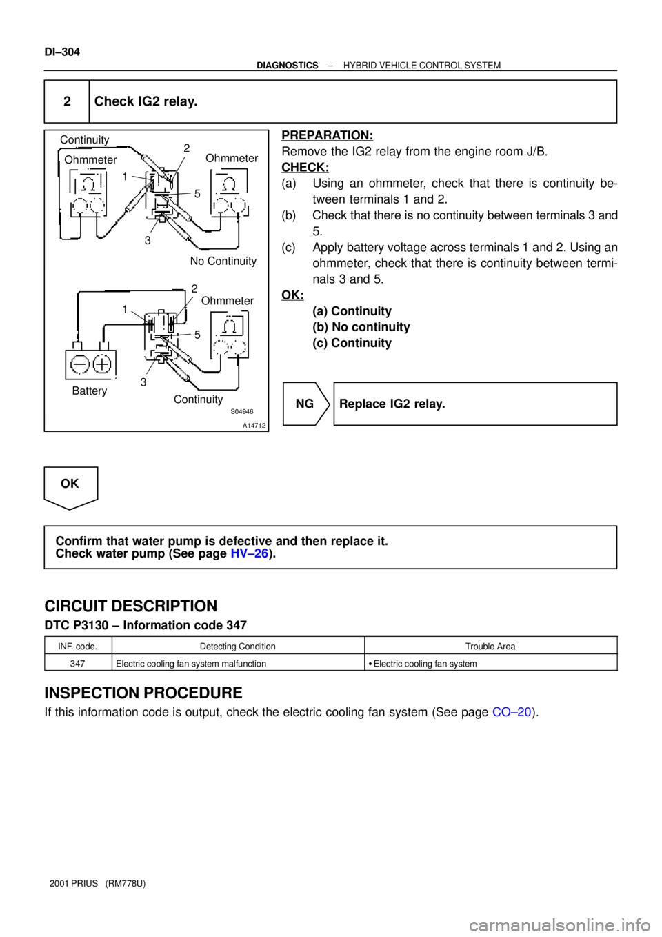
2 Check IG2 relay.
PREPARATION:
Remove the IG2 relay from the engine room J/B.
CHECK:
(a) Using an ohmmeter, check that there is continuity be-
tween terminals 1 and 2.
(b) Check that there is no continuity between terminals 3 and
5.
(c) Apply battery voltage across terminals 1 and 2. Using an
ohmmeter, check that there is continuity between termi-
nals 3 and 5.
OK:
(a) Continuity
(b) No continuity
(c) Continuity
NG Replace IG2 relay.
OK
Confirm that water pump is defective and then replace it.
Check water pump (See page HV±26).
CIRCUIT DESCRIPTION
DTC P3130 ± Information code 347
INF. code.Detecting ConditionTrouble Area
347Electric cooling fan system malfunction�Electric cooling fan system
INSPECTION PROCEDURE
If this information code is output, check the electric cooling fan system (See page CO±20).
Page 902 of 1943
± DIAGNOSTICSHYBRID VEHICLE CONTROL SYSTEM
DI±311
2001 PRIUS (RM778U)
INSPECTION PROCEDURE
1 Is DTC P0500 of engine ECU being output?
YES Check DTC P0500.
NO
Check continuity of wire harness between J26 J/B G terminal and HV ECU SPDI terminal
and repair wire harness.
Page 903 of 1943

DI2VS±03
Prius Problem Check Sheet
Vehicle
Specifications
Please fill in the blanks within bold frame.Name of DealerPerson in Charge at
HeadquartersPerson in Charge
at Dealer
Model CodeOffice
Vehicle Delivery Date
Frame No.
Unit No. etc.
Option . . . :
( ) Navigation (equipped by ( ) MOP ( ) dealer) ( ) Cold climate specification
( ) others( )Problem Occurrence Date
Service Entry Date NHW11±
. .
. .Odometer Reading
Registration datekm
. .
Contents of complaint (Status when and before/after occurring in
the order of events as correct as possible)Characteristics of Customer
Gender
Age
Occupation
Vehicle used before
Main use area
Frequency in use
Others times/day or
week or month
Status of engineOthers
Interview Results
( ) Male ( ) Female
suburbs ( ) %
Others ( ) ( ) %
city area ( ) %
mountain area ( ) %
Driving ConditionRoad Condition
Vehicle Condition
Vehicle Speed
km/h
mph
( ) when starting
( ) when according
( ) When
normal driving
( ) when
decelerating
( ) when braking
( ) when shopping
( ) when parking
( ) when turning
( ) when
ABS actuating
( ) others
( )( ) flat road
( ) up hill ( ) down
hill incline of
° /%
distance
km
mph
( ) dry paved road
( ) wet paved road
( ) rough paved road
( ) unpaved road
( ) snowy/frozen
road
( ) bump/curb
( ) others
( )( ) when starting
( ) right after
starting
( ) until min.
after starting
( ) until min.
after starting
of driving
( ) when shopping
system
( ) while shopping
engine
( ) when starting
engine
( ) when revolving
engineHV Battery
indication
( ) 4/4 ( ) 3/4
( ) 2/4 ( ) 1/4
( ) unidentified
Shift position
(indication)
( ) P ( ) R ( ) N
( ) D ( ) B
( ) when operating
"Weather:
A/C status
( ) no indication
( ) unidentified
( ) A/C ( ) FULL
( ) OFF
( ) unidentifiedWarning light
(MIL)
( ) ON ( ) OFF
( ) PS
( ) main battery
( ) HV!
( ) engine
( ) charge
( ) output
control
( ) brake
( ) ABS
( ) others
( )
Temperature:
°C
Brake operation
( ) brake slowly
( ) Brake suddenly
( ) use two pedals
system
Frequency in
occurrence
( ) always
( ) sometimes
( ) only once
miles
°F
Fuel level
( ) segments
± DIAGNOSTICSHV BATTERY CONTROL SYSTEM
DI±313
2001 PRIUS (RM778U)
CUSTOMER PROBLEM ANALYSIS CHECK
Page 911 of 1943

A14081
AM
A14082
Engine Room J/B
HV Fuse
DI±324
± DIAGNOSTICSHV BATTERY CONTROL SYSTEM
2001 PRIUS (RM778U)
INSPECTION PROCEDURE
HINT:
Read freeze frame data using a TOYOTA hand±held tester or OBD II scan tool. Because freeze frame data
records the battery condition when the malfunction is detected. When troubleshooting, this is useful for
knowing the battery condition.
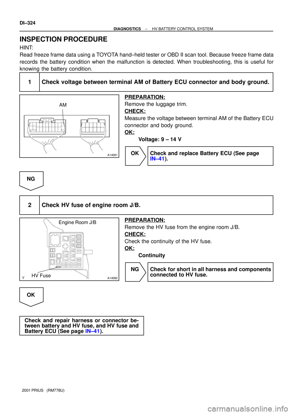
1 Check voltage between terminal AM of Battery ECU connector and body ground.
PREPARATION:
Remove the luggage trim.
CHECK:
Measure the voltage between terminal AM of the Battery ECU
connector and body ground.
OK:
Voltage: 9 ± 14 V
OK Check and replace Battery ECU (See page
IN±41).
NG
2 Check HV fuse of engine room J/B.
PREPARATION:
Remove the HV fuse from the engine room J/B.
CHECK:
Check the continuity of the HV fuse.
OK:
Continuity
NG Check for short in all harness and components
connected to HV fuse.
OK
Check and repair harness or connector be-
tween battery and HV fuse, and HV fuse and
Battery ECU (See page IN±41).
Page 924 of 1943

± DIAGNOSTICSHV BATTERY CONTROL SYSTEM
DI±341
2001 PRIUS (RM778U) 4/27/01
DTC P3011±P3029 Battery Block # Malfunction
CIRCUIT DESCRIPTION
Internal resistance of each battery module is measured, detecting battery deterioration for each block, 1 to
19. Nineteen blocks of battery modules are arranged in the order of 1 to 19 from the ECU side.
DTC No.DTC Detecting ConditionTrouble Area
P3011±P3029Battery internal resistance is abnormal.�Battery ECU
�Battery pack
INSPECTION PROCEDURE
1 Are there any other codes (besides DTC P3011±P3029) being outputs?
YES Go to relevant DTC chart.
NO
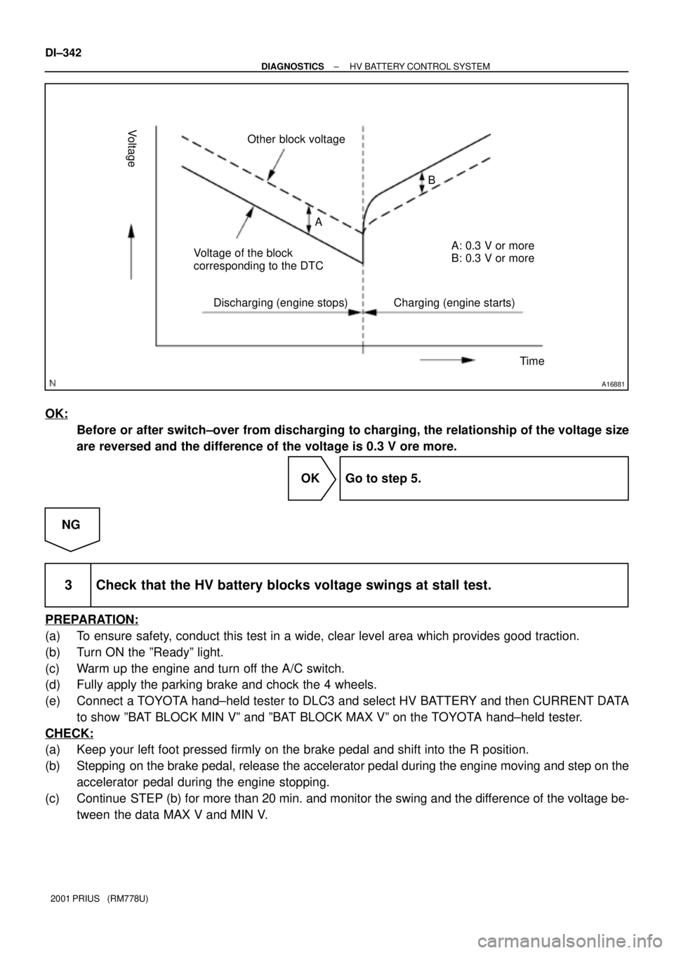
2 Check that the block voltage during charging/ discharging.
PREPARATION:
(a) To ensure safety, conduct this test in a wide, clear level area which provides good traction.
(b) Turn ON the ºREADYº light.
(c) Warm up the engine and turn off the A/C switch.
(d) Fully apply the parking brake and chock the 4 wheels.
(e) Connect a TOYOTA hand±held tester to DLC3 and select HV BATTERY and then CURRENT DATA.
(f) Show voltage of the block corresponding to the DTC and other block (any block except the above±
mentioned block).
CHECK:
(a) Keep your left foot pressed firmly on the brake pedal and shift into the R position.
(b) Confirm the engine stopped in the R position. Step on the accelerator pedal until the engine starts,
stepping on the brake pedal firmly.
(c) Release the accelerator pedal when the engine starts. At the same time, monitor the change of the
voltage before engine starting (during discharging) and after engine starting (during charging).
DI82C±01
Page 925 of 1943

A16881
Voltage
Other block voltage
Voltage of the block
corresponding to the DTC
Discharging (engine stops) Charging (engine starts)A: 0.3 V or more A
B: 0.3 V or more B
Time
DI±342
± DIAGNOSTICSHV BATTERY CONTROL SYSTEM
2001 PRIUS (RM778U)
OK:
Before or after switch±over from discharging to charging, the relationship of the voltage size
are reversed and the difference of the voltage is 0.3 V ore more.
OK Go to step 5.
NG
3 Check that the HV battery blocks voltage swings at stall test.
PREPARATION:
(a) To ensure safety, conduct this test in a wide, clear level area which provides good traction.
(b) Turn ON the ºReadyº light.
(c) Warm up the engine and turn off the A/C switch.
(d) Fully apply the parking brake and chock the 4 wheels.
(e) Connect a TOYOTA hand±held tester to DLC3 and select HV BATTERY and then CURRENT DATA
to show ºBAT BLOCK MIN Vº and ºBAT BLOCK MAX Vº on the TOYOTA hand±held tester.
CHECK:
(a) Keep your left foot pressed firmly on the brake pedal and shift into the R position.
(b) Stepping on the brake pedal, release the accelerator pedal during the engine moving and step on the
accelerator pedal during the engine stopping.
(c) Continue STEP (b) for more than 20 min. and monitor the swing and the difference of the voltage be-
tween the data MAX V and MIN V.
Page 926 of 1943
A16880
The difference of the voltage
between the date VMAX and VMIN
SwingVMAX data
The engine start Test startTime
Voltage
Swing
Swing
SwingVMIN data
± DIAGNOSTICSHV BATTERY CONTROL SYSTEM
DI±343
2001 PRIUS (RM778U) 4/27/01 OK:
Standard voltage swing: Less than 2 V
NG Replace the battery ECU (See page IN±41).
OK
4 Check the difference of the voltage between the data V MAX and V MIN.
Standard voltage difference: Less than 1.2 V
YES Replace the battery ECU. (See page IN±41).
NO
5 Replace the battery pack assembly, and initialize the battery ECU by performing
an active test.