Page 757 of 1943
A14004
MREL
(+) (±)
A13630
Engine Room J/B
EFI Fuse
± DIAGNOSTICSENGINE
DI±159
2001 PRIUS (RM778U)
6 Check voltage between terminal MREL of ECM connector and body ground.
PREPARATION:
(a) Remove the ECM with connector still connected (See
page SF±62).
(b) Turn the ignition switch ON.
CHECK:
Measure the voltage between terminal MREL of the ECM con-
nector and body ground.
OK:
Voltage: 9 ± 14 V
NG Check and replace ECM (See page IN±41).
OK
7 Check EFI1 fuse.
PREPARATION:
Remove the EFI fuse from the engine room J/B.
CHECK:
Check continuity of EFI fuse.
OK:
Continuity
NG Check for short in all harness and components
connected to EFI1 fuse (See attached wiring
diagram).
OK
8 Check EFI main relay (Marking: EFI MAIN) (See page SF±37).
NG Replace EFI main relay.
OK
Page 758 of 1943
DI±160
± DIAGNOSTICSENGINE
2001 PRIUS (RM778U)
9 Check for open and short in harness and connector between terminal MREL of
ECM and body ground (See page IN±41).
NG Repair or replace harness or connector.
OK
Check and repair harness or connector be-
tween EFI1 fuse and battery.
Page 760 of 1943
A14007
FC ON
(±) (+) DI±162
± DIAGNOSTICSENGINE
2001 PRIUS (RM778U)
INSPECTION PROCEDURE
TOYOTA hand±held tester:
1 Connect TOYOTA hand±held tester and check operation of fuel pump (See page
DI±3).
OK Proceed to next circuit inspection shown on
problem symptoms table (See page DI±22).
NG
2 Check for ECM power source circuit (See page DI±156).
NG Repair or replace.
OK
3 Check circuit opening relay (Marking: C/OPN) (See page SF±38).
NG Replace circuit opening relay.
OK
4 Check voltage between terminal FC of ECM and body ground.
PREPARATION:
(a) Remove the ECM with connector still connected (See
page SF±62).
(b) Turn the ignition switch ON.
CHECK:
Measure the voltage between terminal FC of the ECM and body
ground.
OK:
Voltage: 9 ± 14 V
Page 761 of 1943
± DIAGNOSTICSENGINE
DI±163
2001 PRIUS (RM778U)
OK Go to step 5.
NG
Check for open in harness and connector between EFI main relay and circuit opening relay (Mark-
ing: C/OPN), circuit opening relay and ECM (See page IN±41).
5 Check fuel pump (See page SF±6).
NG Repair or replace fuel tank assembly.
OK
6 Check for open in harness and connector between circuit opening relay and fuel
pump and body ground (See page IN±41).
NG Repair or replace harness or connector.
OK
Check and replace ECM (See page IN±41).
Page 762 of 1943
A14005B10046
A14006
ON
FC
Fuel Inlet Hose
OFF
ON
DI±164
± DIAGNOSTICSENGINE
2001 PRIUS (RM778U)
OBD II scan tool (excluding TOYOTA hand±held tester):
1 Check operation of fuel pump.
PREPARATION:
(a) Remove the ECM with connector still connected (See
page SF±62).
(b) Turn the ignition switch ON.
CHECK:
(a) Connect between terminal FC of the ECM connector and
body ground.
(b) Check for fuel pressure in the fuel inlet hose when it is
pinched off.
OK:
There is pressure in fuel inlet hose.
HINT:
At this time, you will hear a fuel return flowing noise.
OK Proceed to next circuit inspection shown on
problem symptoms table (See page DI±22).
NG
2 Check for ECM power source circuit (See page DI±156).
NG Repair or replace.
OK
3 Check circuit opening relay (Marking: C/OPN) (See page SF±38).
NG Replace circuit opening relay.
OK
Page 763 of 1943
± DIAGNOSTICSENGINE
DI±165
2001 PRIUS (RM778U)
4 Check voltage between terminal FC of ECM and body ground
(See page DI±161).
OK Go to step 5.
NG
Check for open in harness and connector between EFI main relay and circuit opening relay (Mark-
ing: C/OPN), circuit opening relay and ECM (See page IN±41).
5 Check fuel pump (See page SF±6).
NG Repair or replace fuel tank assembly.
OK
6 Check for open in harness and connector between circuit opening relay and fuel
pump and body ground (See page IN±41).
NG Repair or replace harness or connector.
OK
Check and replace ECM (See page IN±41).
Page 764 of 1943

A14037
Combination MeterECM
Instrument Panel J/B
W
BatteryE10 IG1 Relay
6
J11
J/C IG1C11
C10
ID DC/DCG±R
2A
A 5
W
W±B
F114
3GAUGE
Ignition SW 22
2 3B±Y
21
2 1
1 1
MAINL
AM1
B±G4
FL Block No. 1FL Block No. 2 F1312D
2B 2K 2H
86 5
AM1
W±G
MIL
DI±166
± DIAGNOSTICSENGINE
2001 PRIUS (RM778U)
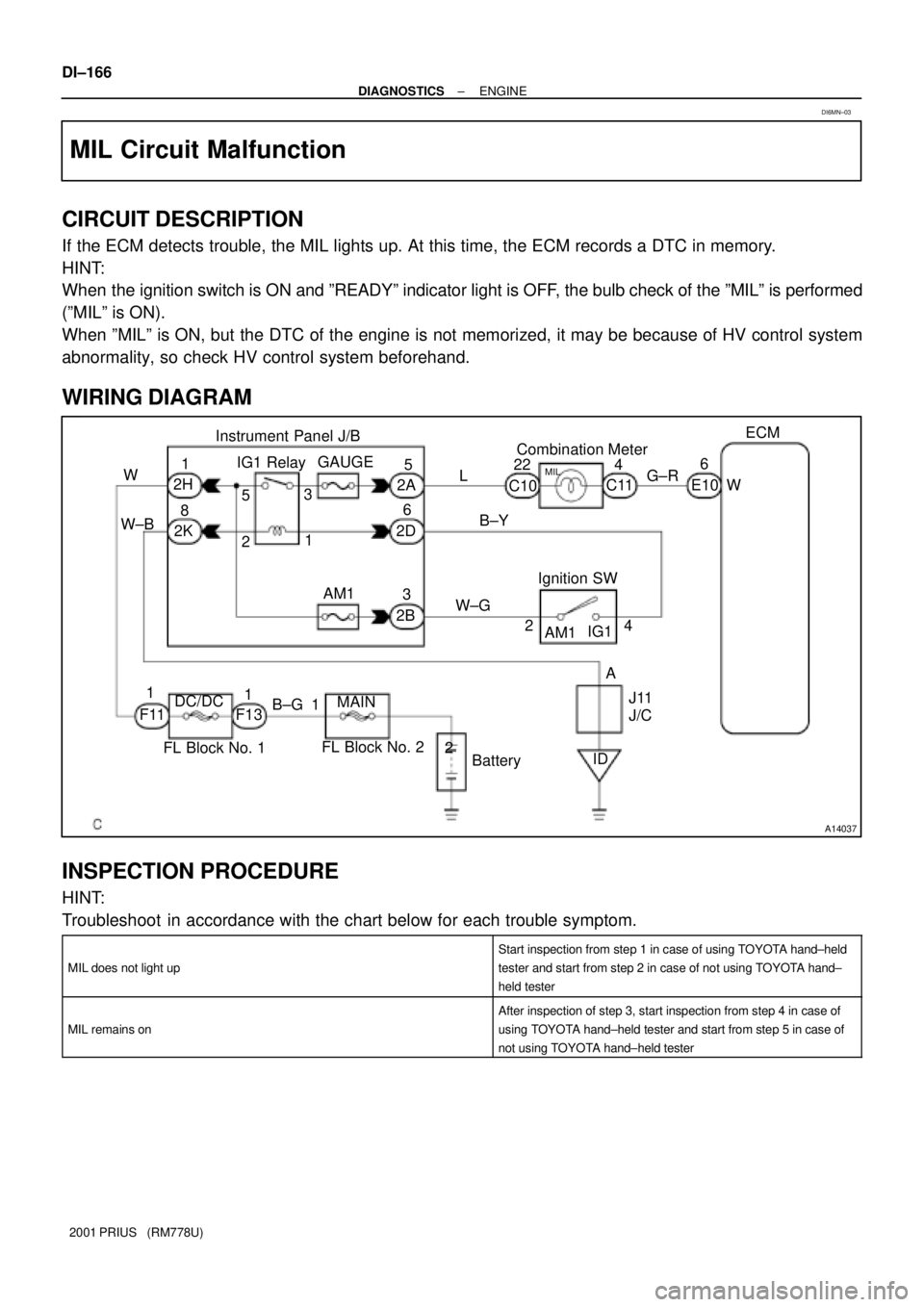
MIL Circuit Malfunction
CIRCUIT DESCRIPTION
If the ECM detects trouble, the MIL lights up. At this time, the ECM records a DTC in memory.
HINT:
When the ignition switch is ON and ºREADYº indicator light is OFF, the bulb check of the ºMILº is performed
(ºMILº is ON).
When ºMILº is ON, but the DTC of the engine is not memorized, it may be because of HV control system
abnormality, so check HV control system beforehand.
WIRING DIAGRAM
INSPECTION PROCEDURE
HINT:
Troubleshoot in accordance with the chart below for each trouble symptom.
MIL does not light up
Start inspection from step 1 in case of using TOYOTA hand±held
tester and start from step 2 in case of not using TOYOTA hand±
held tester
MIL remains on
After inspection of step 3, start inspection from step 4 in case of
using TOYOTA hand±held tester and start from step 5 in case of
not using TOYOTA hand±held tester
DI6MN±03
Page 765 of 1943
± DIAGNOSTICSENGINE
DI±167
2001 PRIUS (RM778U)
1 Inspect diagnosis (normal mode, check mode) (See page DI±3).
OK Check and replace ECM (See page IN±41).
NG
2 Check MIL.
See combination meter troubleshooting on page BE±2.
NG Repair or replace bulb or combination meter as-
sembly.
OK
3 Check that ECM connectors are securely connected to ECM.
NO Connect connector to ECM.
YES
Check for open circuit in harness and connector between combination meter and ECM (See
page IN±41).
4 Check operation of MIL (See step 1).
OK Check and replace ECM (See page IN±41).
NG