Page 35 of 1943
2001 PRIUS (EWD414U)
G
Position of Parts in Engine Compartment
I 1 Ignition Coil and Igniter No.1
I 2 Ignition Coil and Igniter No.2
I 3 Ignition Coil and Igniter No.3
I 4 Ignition Coil and Igniter No.4
I 5 Injector No.1
I 6 Injector No.2
I 7 Injector No.3
I 8 Injector No.4
I 9 Inverter
I 10 Inverter
I 11 Inverter
I 12 Inverter
I 13 Inverter
I 14 Inverter
K 1 Knock Sensor
M 1 Mass Air Flow Meter
M 2 Motor Generator No.1
M 3 Motor Generator No.2
M 4 Motor Generator No.2N 1 Noise Filter (Ignition)
O 1 Oil Pressure SW
R 1 Radiator Fan Motor
S 1 Steering Shaft Torque Sensor
T 1 Theft Deterrent Horn
T 2 Throttle Control Motor
T 3 Throttle Position Sensor
V 1 Vacuum Sensor (HC Adsorber and Catalyst System)
V 2 VSV (EVAP)
V 3 VSV (HC Adsorber and Catalyst System)
W 1 Washer Motor
W 2 Water Pump Motor (A/C)
W 3 Water Pump Motor (Inverter)
W 4 Water Temp. SW
Page 218 of 1943

L PART NUMBER OF CONNECTORS
Code Part Name Part NumberCodePart Name Part Number
Note : Not all of the above part numbers of the connector are established for the supply.
2001 PRIUS (EWD414U) L 2
License Plate Light LH90980±11148L 3License Plate Light RH90980±11148
L 4Luggage Compartment Door Unlock SW90980±11212
L 5Luggage Compartment Light90980±11148
L 6Luggage Compartment Light SW90980±11097
M 1Mass Air Flow Meter90980±11317
M 2Motor Generator No.190980±11658
M 3Motor Generator No.290980±11034
M 4Motor Generator No.290980±11143
M 5Multi Display90980±11911
M 6Multi Display90980±11923
M 7Multi Display90980±10799
N 1Noise Filter (Ignition)90980±10843
N 2Navigation ECU90980±11973
N 3Navigation ECU90980±11923
N 4Noise Filter (Rear Window Defogger)90980±11259
O 1Oil Pressure SW90980±11363
P 1Park/Neutral Position SW90980±11535
P 2Parking Brake SW90980±11147
P 3PTC Heater90980±10903
P 4PTC Heater90980±10867
P 5Personal Light90980±11212
P 6Power Window Control SW Front RH
P 7Power Window Control SW Rear LH90980±10797
P 8Power Window Control SW Rear RH
P 9Power Window Master SW90980±11469
P10Power Window Motor Front LH90980±11011
P11Power Window Motor Front RH
P12Power Window Motor Rear LH90980±10860
P13Power Window Motor Rear RH
P14Pretensioner LH90980±11884
P15Pretensioner RH90980±11862
R 1Radiator Fan Motor90980±11237
R 2Radio and Player90980±10996
R 3Radio and Player90980±10997
R 4Radio and Player90980±10903
R 5Remote Control Mirror SW90980±11657
R 6Rear Combination Light LH90980±11011R 7Rear Combination Light RH90980±11011
R 8Rear Speaker LH90980±10935R 9Rear Speaker RH90980±10935
R10Remote Control Mirror LH90980±11587R11Remote Control Mirror RH90980±11587
S 1Steering Shaft Torque Sensor90980±10942
S 2Shift Lock ECU90980±11488
S 3Stop Light SW90980±11118
S 4Side Airbag Sensor LH90980±11857S 5Side Airbag Sensor RH90980±11 857
S 6Side Airbag Squib LH90980±11864S 7Side Airbag Squib RH90980±11864
S 8System Main Relay90980±11529
S 9System Main Relay82675±36050S10System Main Relay82675±36050
S11System Main Relay±S12System Main Relay±
T 1Theft Deterrent Horn90980±10619
T 2Throttle Control Motor90980±11162
T 3Throttle Position Sensor90980±10711
T 4Transponder Key Computer90980±11475
T 5Turn Signal Flasher Relay90980±10799
T 6Tension Reducer Solenoid90980±11918
U 1Unlock Warning SW and Key Interlock
Solenoid90980±10795
V 1Vacuum Sensor (HC Adsorber and Catalyst
System)90980±10845
V 2VSV (EVAP)90980±11156
V 3VSV (HC Adsorber and Catalyst System)90980±11149
V 4Vapor Pressure Sensor90980±11143
V 5VSV (Canister Closed Valve)90980±11156
V 6VSV (Parge Flow Switching Valve)90980±11859
W 1Washer Motor90980±10981
W 2Water Pump Motor (A/C)90980±10887
W 3Water Pump Motor (Inverter)90980±11003
W 4Water Temp. SW90980±11235
W 5Wireless Door Control Receiver90980±11909
Page 286 of 1943

ENGINE ± 1NZ-FXE ENGINE45
�FEATURES OF 1NZ-FXE ENGINE
The 1NZ-FXE engine has been able to achieve the following performance through the adoption of the items
listed below.
(1) High performance and fuel economy
(2) Low noise and vibration
(3) Lightweight and compact design
(4) Good serviceability
(5) Clean emission
Item
(1)(2)(3)(4)(5)1NZ-FE
The VVT-i system is used.���
High-expansion Atkinson cycle has been adopted.�
An offset crankshaft has been adopted.��
A cylinder block made of aluminum has been adopted.���
A stainless steel exhaust manifold is used for weight reduction.���
A rearward exhaust layout has been adopted to realize the early
activation of the catalyst.��
HC Adsorber and catalyst system has been adopted.�
Fuel returnless system has been adopted.��
12-hole type fuel injectors have been adopted.���
The DIS (Direct Ignition System) makes ignition timing
adjustment unnecessary.��
Quick connectors are used to connect the fuel hose with the
fuel pipes.��
The oil filter is installed diagonally downward.��
A timing chain has been adopted.��
A vacuum system that detects leaks in the evaporative
emission control system has been adopted.���
The vapor reducing fuel tank system has been adopted.
This system reduces the amount of fuel vapor that is generated.�
Page 293 of 1943
ENGINE ± 1NZ-FXE ENGINE
182EG08
182EG09
MAIN OIL HOLE
RELIEF
VA LV E
RELIEF
VA LV E
OIL FILTER
OIL PUMP
OIL STRAINER
CRANKSHAFT
JOURNAL
CONNECTING
RODOIL JET
PISTON OIL JET
TIMING CHAINCHAIN
TENSIONER
CYLINDER HEAD
CAMSHAFT TIMING
OIL CONTROL VALVE
FILTER
INTAKE
CAMSHAFT
JOURNALEXHAUST
CAMSHAFT
JOURNAL
CAMSHAFT TIMING
OIL CONTROL VALVE
VVT-i
OIL PAN 52
�LUBRICATION SYSTEM
�The lubrication circuit is fully pressurized and all oil passes through an oil filter.
�A trochoid gear type oil pump, which is driven directly by the crankshaft, has been provided in the front
of the cylinder block.
�The oil filter has been installed diagonally downward from the side of the cylinder block to improve ser-
viceability.
Page 307 of 1943
ENGINE ± 1NZ-FXE ENGINE
182EG23
VSV (for TOYOTA
HCAC System)VSV (for EVAP)Oil Control Valve
ECMIgnition Coil
with IgniterVSV (for Purge Flow Switching Valve)
Charcoal Canister
Vapor
Pressure
Sensor
Trap Filter
VSV (for Canister
Closed Valve) DLC 3
Heated Oxygen Sensor
(Bank 1, Sensor 2)
Heated Oxygen Sensor
(Bank 1, Sensor 1) Engien Coolant
Temp. Sensor Camshaft
Position
Sensor
Injector Crankshaft
Position
Sensor Knock
Sensor Throttle
Control
Motor Mass Air
Flow Meter 66
4. Layout of Components
Page 414 of 1943

BODY ELECTRICAL ± AIR CONDITIONING 152
AIR CONDITIONING
�DESCRIPTION
The air conditioning system in the Prius has the following features:
�Both heating and demisting performances are realized by adopting performances are realized by adopting
the 2-way flow heater type air conditioning unit.
�A multi-tank, super-slim structure evaporator has been adopted.
�An automatic air conditioning system which provides enhanced air conditioning comfort according to the
occupant's senses has been adopted.
�A semi-center location air conditioning unit, in which the evaporator and heater core are placed in the ve-
hicle's longitudinal direction, has been adopted.
�A compact, high-performance scroll compressor with oil separator has been adopted.
�The heat exchange efficiency has been improved through the adoption of the sub-cool condenser.
This condenser is integrated with the radiator to minimize the space they occupy in the engine compart-
ment.
�A compact, lightweight, and highly efficient straight flow (full-path flow) aluminium heater core has been
adopted.
This heater core is integrated with a PTC (Positive Temperature Coefficient) heater, which excels in heat-
ing performance.
�PTC heaters have been provided in the air duct at the footwell outlet in front of the air conditioning unit.
However, air conditioning without the PTC heaters is offered as an option on the U.S.A. models.
�An electrical water pump with a bypass valve that provides a stable heater performance even if the engine
is stopped due to a function of the THS (TOYOTA Hybrid System) has been adopted.
�A clean air filter that excels in removing pollen and dust is standard equipment.
Page 511 of 1943
MA00R±17
B08810
± MAINTENANCEENGINE
MA±5
58 Author�: Date�:
2001 PRIUS (RM778U)
ENGINE
INSPECTION
HINT:
Inspect these items when the engine is cold.
1. INSPECT DRIVE BELT
(See page CO±4)
2. REPLACE SPARK PLUGS
(See page IG±1)
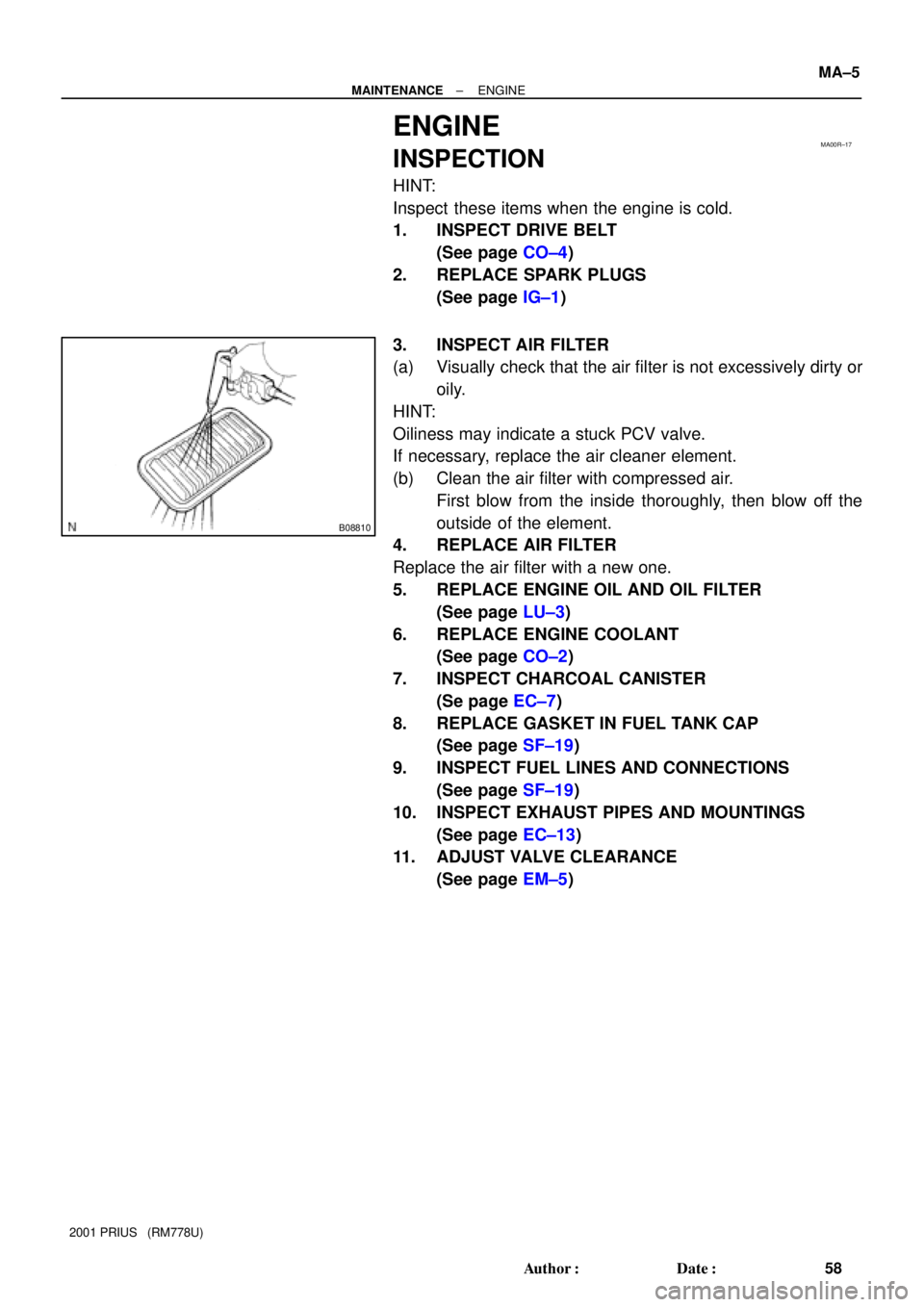
3. INSPECT AIR FILTER
(a) Visually check that the air filter is not excessively dirty or
oily.
HINT:
Oiliness may indicate a stuck PCV valve.
If necessary, replace the air cleaner element.
(b) Clean the air filter with compressed air.
First blow from the inside thoroughly, then blow off the
outside of the element.
4. REPLACE AIR FILTER
Replace the air filter with a new one.
5. REPLACE ENGINE OIL AND OIL FILTER
(See page LU±3)
6. REPLACE ENGINE COOLANT
(See page CO±2)
7. INSPECT CHARCOAL CANISTER
(Se page EC±7)
8. REPLACE GASKET IN FUEL TANK CAP
(See page SF±19)
9. INSPECT FUEL LINES AND CONNECTIONS
(See page SF±19)
10. INSPECT EXHAUST PIPES AND MOUNTINGS
(See page EC±13)
11. ADJUST VALVE CLEARANCE
(See page EM±5)
Page 529 of 1943
PP3AZ±01
± PREPARATIONLUBRICATION
PP±15
76 Author�: Date�:
2001 PRIUS (RM778U)
LUBRICATION
SST (Special Service Tools)
09228±06501Oil Filter Wrench