Page 725 of 1943

A02397
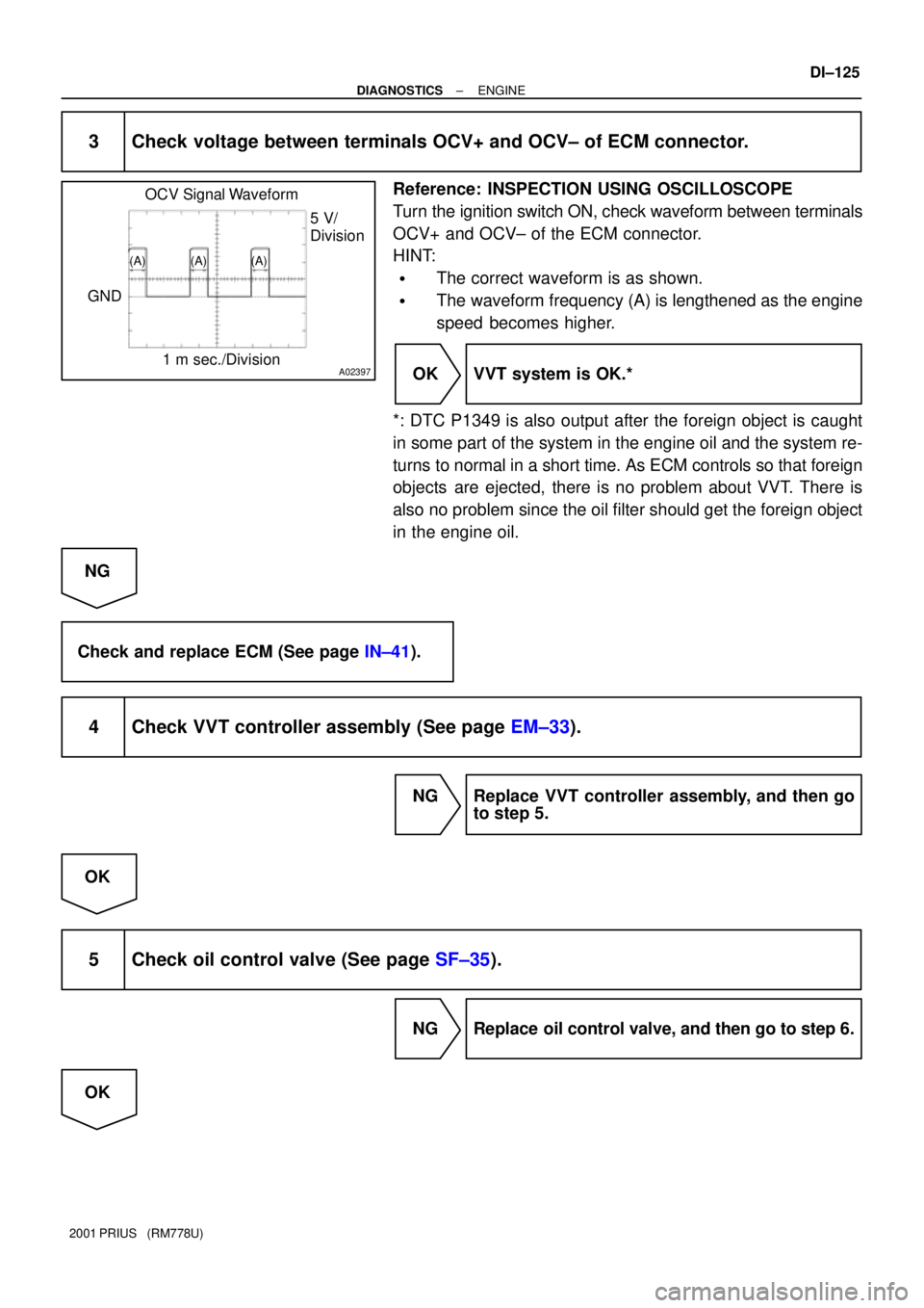
OCV Signal Waveform
1 m sec./Division5 V/
Division
GND
(A) (A) (A)
± DIAGNOSTICSENGINE
DI±125
2001 PRIUS (RM778U)
3 Check voltage between terminals OCV+ and OCV± of ECM connector.
Reference: INSPECTION USING OSCILLOSCOPE
Turn the ignition switch ON, check waveform between terminals
OCV+ and OCV± of the ECM connector.
HINT:
�The correct waveform is as shown.
�The waveform frequency (A) is lengthened as the engine
speed becomes higher.
OK VVT system is OK.*
*: DTC P1349 is also output after the foreign object is caught
in some part of the system in the engine oil and the system re-
turns to normal in a short time. As ECM controls so that foreign
objects are ejected, there is no problem about VVT. There is
also no problem since the oil filter should get the foreign object
in the engine oil.
NG
Check and replace ECM (See page IN±41).
4 Check VVT controller assembly (See page EM±33).
NG Replace VVT controller assembly, and then go
to step 5.
OK
5 Check oil control valve (See page SF±35).
NG Replace oil control valve, and then go to step 6.
OK
Page 726 of 1943
DI±126
± DIAGNOSTICSENGINE
2001 PRIUS (RM778U)
6 Check blockage of oil control valve, oil check valve and oil pipe No.1.
NG Repair or replace.
OK
7 Check whether or not DTC P1349 is stored.
PREPARATION:
(a) Clear the DTC (See page DI±3).
(b) Perform simulation test.
CHECK:
Check whether or not DTC P1349 is stored (See page DI±3).
OK:
DTC P1349 is not stored
OK VVT system is OK.*
*: DTC P1349 is also output after the foreign object is caught
in some part of the system in the engine oil and the system re-
turns to normal in a short time. As ECM controls so that foreign
objects are ejected, there is no problem about VVT. There is
also no problem since the oil filter should get the foreign object
in the engine oil.
NG
Replace ECM.
Page 728 of 1943
A13624
E2 VC ON
(+)
(±)
DI±128
± DIAGNOSTICSENGINE
2001 PRIUS (RM778U)
When using hand±held tester:
1 Connect hand±held tester, and read value.
PREPARATION:
(a) Connect the hand±held tester to the DLC3.
(b) Turn the ignition switch ON and push the hand±held tester main switch ON.
CHECK:
Read the value of the manifold absolute pressure on the hand±held tester.
OK:
Same as atmospheric pressure.
OK Check for intermittent problems
(See page DI±3).
NG
2 Check voltage between terminals VC and E2 of engine ECU Connector.
PREPARATION:
(a) Remove the ECM with connector still connected (See
page SF±62).
(b) Turn the ignition switch ON.
CHECK:
Measure the voltage between terminals VC and E2 of the en-
gine ECU connector.
OK:
Voltage: 4.5 ± 5.5 V
NG Check and replace engine ECU
(See page IN±41).
OK
Page 729 of 1943

A14021
HCLSON
A13624
E2 VC ON
(+)
(±)
± DIAGNOSTICSENGINE
DI±129
2001 PRIUS (RM778U)
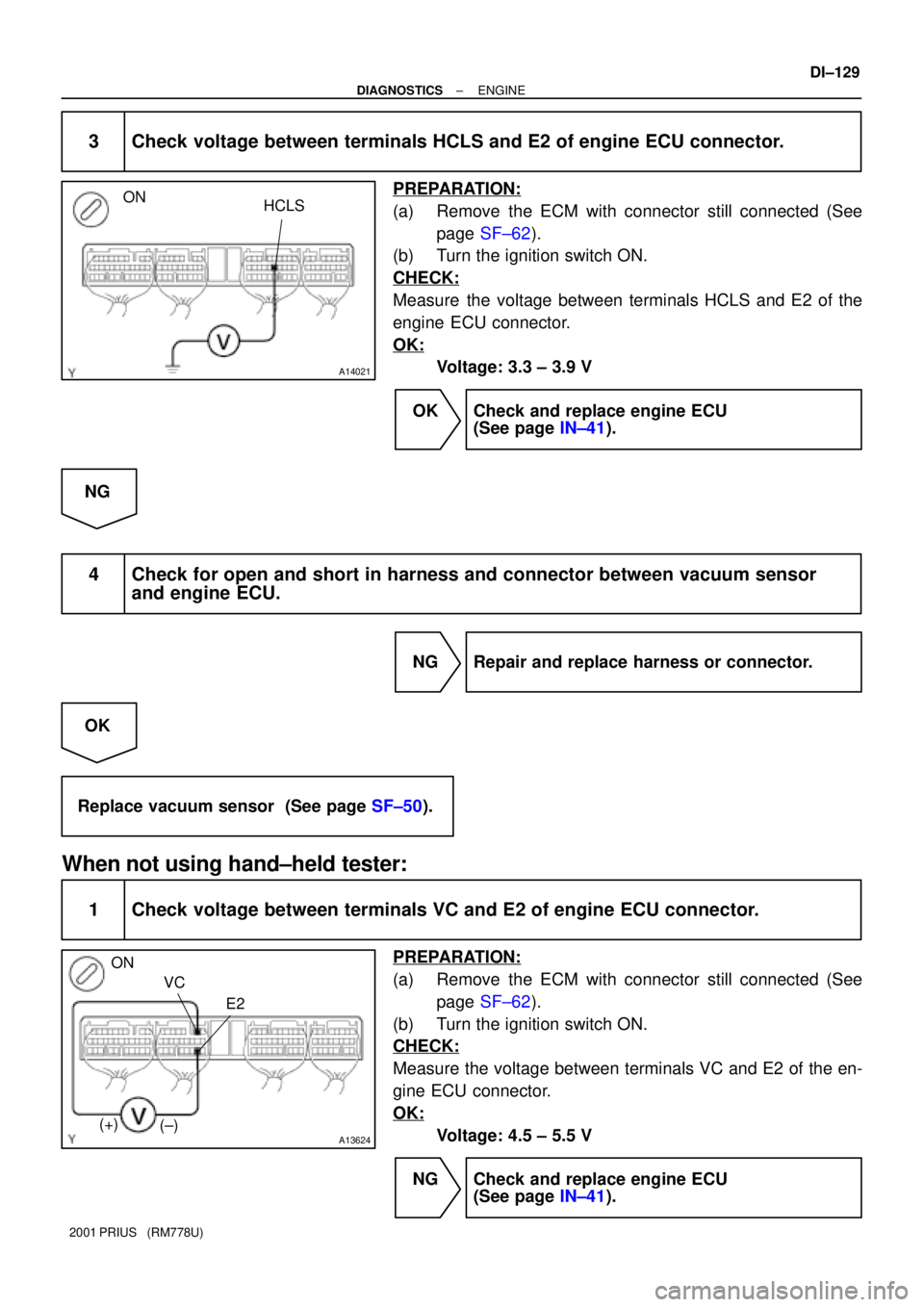
3 Check voltage between terminals HCLS and E2 of engine ECU connector.
PREPARATION:
(a) Remove the ECM with connector still connected (See
page SF±62).
(b) Turn the ignition switch ON.
CHECK:
Measure the voltage between terminals HCLS and E2 of the
engine ECU connector.
OK:
Voltage: 3.3 ± 3.9 V
OK Check and replace engine ECU
(See page IN±41).
NG
4 Check for open and short in harness and connector between vacuum sensor
and engine ECU.
NG Repair and replace harness or connector.
OK
Replace vacuum sensor (See page SF±50).
When not using hand±held tester:
1 Check voltage between terminals VC and E2 of engine ECU connector.
PREPARATION:
(a) Remove the ECM with connector still connected (See
page SF±62).
(b) Turn the ignition switch ON.
CHECK:
Measure the voltage between terminals VC and E2 of the en-
gine ECU connector.
OK:
Voltage: 4.5 ± 5.5 V
NG Check and replace engine ECU
(See page IN±41).
Page 730 of 1943
A14021
HCLSON
DI±130
± DIAGNOSTICSENGINE
2001 PRIUS (RM778U)
OK
2 Check voltage between terminals HCLS and E2 of engine ECU connector.
PREPARATION:
(a) Remove the ECM with connector still connected (See
page SF±62).
(b) Turn the ignition switch ON.
CHECK:
Measure the voltage between terminals HCLS and E2 of the
engine ECU connector.
OK:
Voltage: 3.3 ± 3.9 V
OK Check and replace engine ECU
(See page IN±41).
NG
3 Check for open and short in harness and connector between engine ECU and
vacuum sensor (See page IN±41).
NG Repair or replace harness or connector.
OK
Replace vacuum sensor.
Page 732 of 1943
DI±132
± DIAGNOSTICSENGINE
2001 PRIUS (RM778U)
2 Check vacuum sensor for HC adsorber and catalyst system (See page SF±51).
NG Replace vacuum sensor.
OK
Check vacuum line for vacuum sensor for
blockage.
Page 733 of 1943

± DIAGNOSTICSENGINE
DI±133
2001 PRIUS (RM778U)
DTC P1436 Bypass Valve Malfunction
CIRCUIT DESCRIPTION
Before the engine is started, the bypass valve remains open. When the engine is cold started, the ECM out-
puts a signal to the VSV (for HC adsorber and catalyst system), which open the passage between the intake
manifold and the actuator, thus applying a vacuum to the actuator. As a result, the bypass valve closes.
Immediately after the engine has started, the exhaust gases pass through the adsorber material in with HC
becomes adsorbed and stored for a certain length of time (until the temperature of the front TWC rises).
Thus, the release of HC into the atmosphere is prevented when the temperature of the TWC is low.
After the TWC has warmed up, the VSV closes the passage between the intake manifold and the actuator,
causing the bypass valve to open. Then, as the temperature of the rear TWC rises, the temperature of the
adsorber material that surrounds it also rises, and the HC starts to desorb, and becomes cleaned by the
TWC.
Furthermore, this system activates the VSV when decelerating and the HC adsorber has become the speci-
fied temperature, allowing the vacuum from the intake manifold to close the bypass valve in order to scav-
enge the HC that remains in the adsorber material.
DTC No.DTC Detecting ConditionTrouble Area
P1436
With cold start when the water temperature and intake air
temperature were ±10 °C (14 °F)to 40 °C (104 °F), and
when the water temperature has reached 45 °C (113 °F) or
more and the engine load factor has become more than 30
%, the valve operation is not preformed normally.
�Vacuum line
�Actuator
�Front exhaust pipe
INSPECTION PROCEDURE
1 Check vacuum hose and tube between VSV and actuator for HC adsorber and
catalyst system.
CHECK:
Check that the vacuum hose and tube for clog and deformation.
NG Repair or replace.
OK
2 Check actuator operation (See page EC±13).
OK Recheck after assembly.
NG
DI7T0±01
Page 734 of 1943
DI±134
± DIAGNOSTICSENGINE
2001 PRIUS (RM778U)
3 Check that dirt such as mud is deposited on lever and shaft of bypass valve.
YES Remove dirt and check again.
NO
4 Check that actuator's rod and bracket is deformed.
YES Repair or replace actuator.
NO
5 Check bypass valve operation (See page EC±13).
NG Replace front exhaust pipe.
OK
6 Check actuator operation (See page EC±13).
NG Replace actuator.
OK
Repair or replace front exhaust pipe.