Page 1484 of 1943
A13934
A13907
± ENGINE MECHANICALTIMING CHAIN
EM±25
2001 PRIUS (RM778U)
16. CONNECT CONNECTORS
(a) Connect the Camshaft timing oil control valve connector.
(b) Connect the water temperature sensor connector.
(c) Connect the camshaft position sensor connector.
(d) Connect the 2 VSV connectors.
(e) Connect the 4 injector connectors.
(f) Connect the 4 ignition connectors.
17. INSTALL AIR CLEANER ASSEMBLY
(a) Install the air cleaner assembly with the 2 bolts.
(b) Tighten the 2 hose clamps.
(c) Connect the EVAP hose to the air cleaner case.
(d) Connect the MAF meter connector.
18. INSTALL BRAKE RESERVOIR TANK
19. INSTALL OUTER FR COWL TOP PANEL ASSEMBLY
(See page BO±35)
20. FILL WITH ENGINE COOLANT
21. INSTALL ENGINE UNDER COVERS
22. CONNECT BATTERY NEGATIVE (±) TERMINAL AND
HV BATTERY SERVICE PLUG (See page HV±1)
23. ROAD TEST VEHICLE
Check for abnormal noises, shock slippage, correst shift points
and smooth operation.
24. RECHECK ENGINE COOLANT AND HV TRANSAXLE
COOLANT
Page 1492 of 1943
A01479
A01075
Cylinder Block Side
Intake Manifold Side
Exhaust Manifold Side
A01071
EM0580
EM±34
± ENGINE MECHANICALCYLINDER HEAD
2001 PRIUS (RM778U)
5. CLEAN VALVE GUIDE BUSHINGS
Using a valve guide bushing brush and solvent, clean all the
guide bushings.
6. INSPECT FOR FLATNESS
Using a precision straight edge and feeler gauge, measure the
surface contacting the cylinder block and the manifolds for war-
page.
Maximum warpage:
Cylinder block side0.05 mm (0.0020 in.)
Intake Manifold side0.10 mm (0.0394 in.)
Exhaust manifold side0.10 mm (0.0394 in.)
If warpage is greater than maximum, replace the cylinder head.
7. INSPECT FOR CRACKS
Using a dye penetrant, check the combustion chamber, intake
ports, exhaust ports and cylinder block surface for cracks.
If cracked, replace the cylinder head.
8. CLEAN VALVES
(a) Using a gasket scraper, chip off any carbon from the valve
head.
(b) Using a wire brush, thoroughly clean the valve.
Page 1493 of 1943
A01478
Z00052
EM0180
44.5°
EM0181
Margin Thickness
± ENGINE MECHANICALCYLINDER HEAD
EM±35
2001 PRIUS (RM778U)
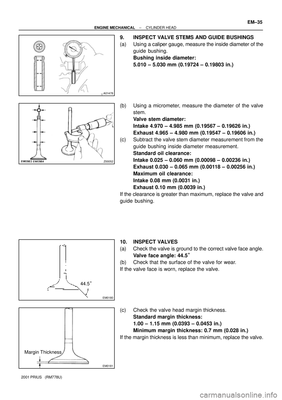
9. INSPECT VALVE STEMS AND GUIDE BUSHINGS
(a) Using a caliper gauge, measure the inside diameter of the
guide bushing.
Bushing inside diameter:
5.010 ± 5.030 mm (0.19724 ± 0.19803 in.)
(b) Using a micrometer, measure the diameter of the valve
stem.
Valve stem diameter:
Intake 4.970 ± 4.985 mm (0.19567 ± 0.19626 in.)
Exhaust 4.965 ± 4.980 mm (0.19547 ± 0.19606 in.)
(c) Subtract the valve stem diameter measurement from the
guide bushing inside diameter measurement.
Standard oil clearance:
Intake 0.025 ± 0.060 mm (0.00098 ± 0.00236 in.)
Exhaust 0.030 ± 0.065 mm (0.00118 ± 0.00256 in.)
Maximum oil clearance:
Intake 0.08 mm (0.0031 in.)
Exhaust 0.10 mm (0.0039 in.)
If the clearance is greater than maximum, replace the valve and
guide bushing.
10. INSPECT VALVES
(a) Check the valve is ground to the correct valve face angle.
Valve face angle: 44.5°
(b) Check that the surface of the valve for wear.
If the valve face is worn, replace the valve.
(c) Check the valve head margin thickness.
Standard margin thickness:
1.00 ± 1.15 mm (0.0393 ± 0.0453 in.)
Minimum margin thickness: 0.7 mm (0.028 in.)
If the margin thickness is less than minimum, replace the valve.
Page 1494 of 1943
EM2534
Overall Length
A01073
45° Carbide
CutterResiduary
Width
Resurface
A01074
Width
EM0185
45°20°
1.0 ± 1.4 mm
EM0186
75°
1.0 ± 1.4 mm45°
EM±36
± ENGINE MECHANICALCYLINDER HEAD
2001 PRIUS (RM778U)
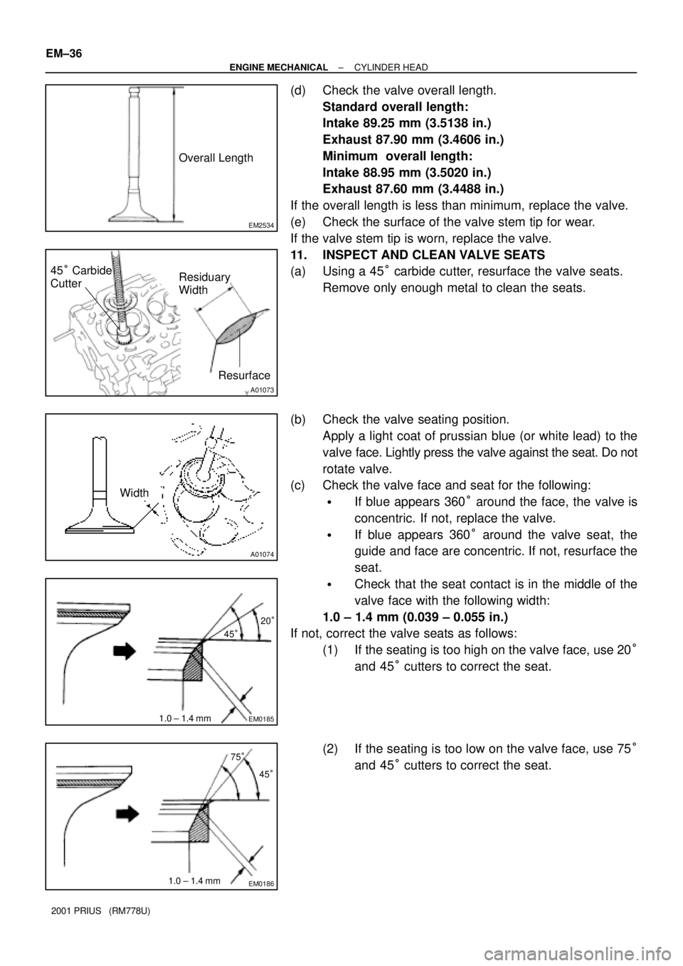
(d) Check the valve overall length.
Standard overall length:
Intake 89.25 mm (3.5138 in.)
Exhaust 87.90 mm (3.4606 in.)
Minimum overall length:
Intake 88.95 mm (3.5020 in.)
Exhaust 87.60 mm (3.4488 in.)
If the overall length is less than minimum, replace the valve.
(e) Check the surface of the valve stem tip for wear.
If the valve stem tip is worn, replace the valve.
11. INSPECT AND CLEAN VALVE SEATS
(a) Using a 45° carbide cutter, resurface the valve seats.
Remove only enough metal to clean the seats.
(b) Check the valve seating position.
Apply a light coat of prussian blue (or white lead) to the
valve face. Lightly press the valve against the seat. Do not
rotate valve.
(c) Check the valve face and seat for the following:
�If blue appears 360° around the face, the valve is
concentric. If not, replace the valve.
�If blue appears 360° around the valve seat, the
guide and face are concentric. If not, resurface the
seat.
�Check that the seat contact is in the middle of the
valve face with the following width:
1.0 ± 1.4 mm (0.039 ± 0.055 in.)
If not, correct the valve seats as follows:
(1) If the seating is too high on the valve face, use 20°
and 45° cutters to correct the seat.
(2) If the seating is too low on the valve face, use 75°
and 45° cutters to correct the seat.
Page 1496 of 1943
EM2011
EM2538
A01452
Plastigage
A12943
A01453
EM±38
± ENGINE MECHANICALCYLINDER HEAD
2001 PRIUS (RM778U)
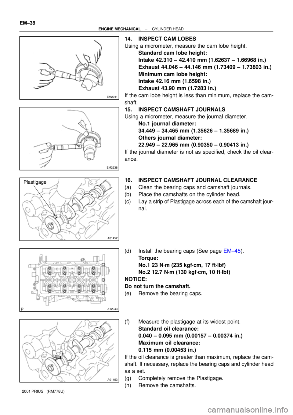
14. INSPECT CAM LOBES
Using a micrometer, measure the cam lobe height.
Standard cam lobe height:
Intake 42.310 ± 42.410 mm (1.62637 ± 1.66968 in.)
Exhaust 44.046 ± 44.146 mm (1.73409 ± 1.73803 in.)
Minimum cam lobe height:
Intake 42.16 mm (1.6598 in.)
Exhaust 43.90 mm (1.7283 in.)
If the cam lobe height is less than minimum, replace the cam-
shaft.
15. INSPECT CAMSHAFT JOURNALS
Using a micrometer, measure the journal diameter.
No.1 journal diameter:
34.449 ± 34.465 mm (1.35626 ± 1.35689 in.)
Others journal diameter:
22.949 ± 22.965 mm (0.90350 ± 0.90413 in.)
If the journal diameter is not as specified, check the oil clear-
ance.
16. INSPECT CAMSHAFT JOURNAL CLEARANCE
(a) Clean the bearing caps and camshaft journals.
(b) Place the camshafts on the cylinder head.
(c) Lay a strip of Plastigage across each of the camshaft jour-
nal.
(d) Install the bearing caps (See page EM±45).
Torque:
No.1 23 N´m (235 kgf´cm, 17 ft´lbf)
No.2 12.7 N´m (130 kgf´cm, 10 ft´lbf)
NOTICE:
Do not turn the camshaft.
(e) Remove the bearing caps.
(f) Measure the plastigage at its widest point.
Standard oil clearance:
0.040 ± 0.095 mm (0.00157 ± 0.00374 in.)
Maximum oil clearance:
0.115 mm (0.00453 in.)
If the oil clearance is greater than maximum, replace the cam-
shaft. If necessary, replace the bearing caps and cylinder head
as a set.
(g) Completely remove the Plastigage.
(h) Remove the camshafts.
Page 1502 of 1943
S05923
Intake Exhaust
Mark
ºNOKº
Gray Surface
Light Brown Surface
A01065
(1)
(2)(3)
(4)
A01061
SST
A07307
EM±44
± ENGINE MECHANICALCYLINDER HEAD
2001 PRIUS (RM778U)
HINT:
The intake valve oil seal is light brown and the exhaust valve oil
seal is gray.
NOTICE:
Pay much attention assembling the oil seal for intake and
exhaust. Assembling the wrong one may cause a failure.
(b) Install the valve (1), spring (2), valve spring (3), and spring
retainer (4).
(c) Using SST, compress the valve spring and place the 2
keepers around the valve stem.
SST 09202±70020 (09202±00010)
(d) Using a plastic±faced hammer and the valve stem (not in
use) tip wound with vinyl tape, lightly tap the valve stem
tip to ensure a proper fit.
NOTICE:
Be careful not to damage the valve stem tip.
3. INSTALL VALVE LIFTERS
(a) Install the valve lifter.
(b) Check that the valve lifter rotates smoothly by hand.
Page 1503 of 1943
EM1IY±02
A11249
Lod No.
A11228
84259
106137
A12126
Front90°90°
± ENGINE MECHANICALCYLINDER HEAD
EM±45
2001 PRIUS (RM778U)
INSTALLATION
HINT:
�Thoroughly clean all parts to be assembled.
�Before installing the parts, apply fresh engine oil to all slid-
ing and rotating surfaces.
�Replace all gaskets and oil seals with new ones.
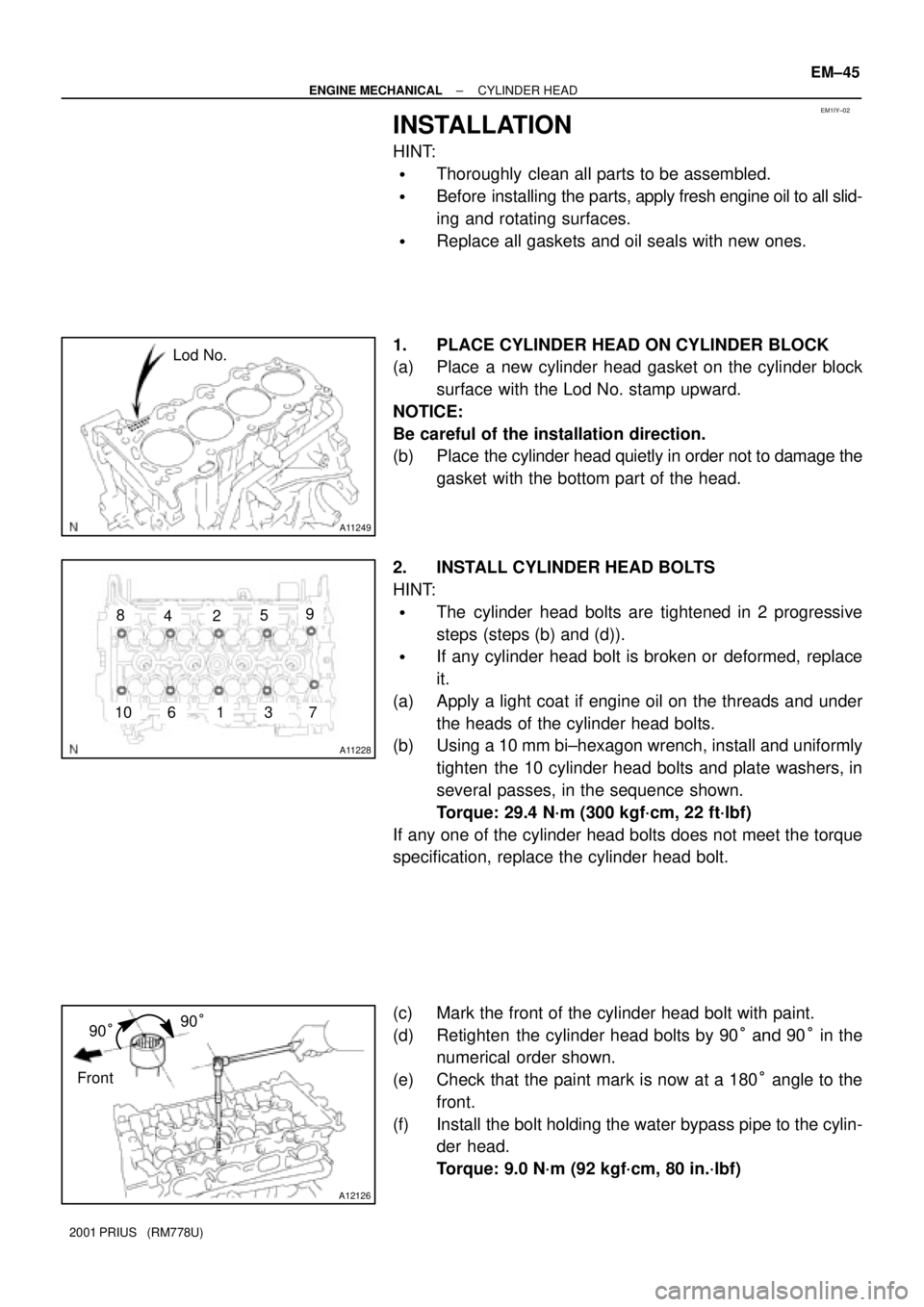
1. PLACE CYLINDER HEAD ON CYLINDER BLOCK
(a) Place a new cylinder head gasket on the cylinder block
surface with the Lod No. stamp upward.
NOTICE:
Be careful of the installation direction.
(b) Place the cylinder head quietly in order not to damage the
gasket with the bottom part of the head.
2. INSTALL CYLINDER HEAD BOLTS
HINT:
�The cylinder head bolts are tightened in 2 progressive
steps (steps (b) and (d)).
�If any cylinder head bolt is broken or deformed, replace
it.
(a) Apply a light coat if engine oil on the threads and under
the heads of the cylinder head bolts.
(b) Using a 10 mm bi±hexagon wrench, install and uniformly
tighten the 10 cylinder head bolts and plate washers, in
several passes, in the sequence shown.
Torque: 29.4 N´m (300 kgf´cm, 22 ft´lbf)
If any one of the cylinder head bolts does not meet the torque
specification, replace the cylinder head bolt.
(c) Mark the front of the cylinder head bolt with paint.
(d) Retighten the cylinder head bolts by 90° and 90° in the
numerical order shown.
(e) Check that the paint mark is now at a 180° angle to the
front.
(f) Install the bolt holding the water bypass pipe to the cylin-
der head.
Torque: 9.0 N´m (92 kgf´cm, 80 in.´lbf)
Page 1505 of 1943
A13933
A11226
A13932
± ENGINE MECHANICALCYLINDER HEAD
EM±47
2001 PRIUS (RM778U)
(d) Temporarily install the timing sprocket bolt.
(e) Hold the hexagon head portion of the camshaft with a
wrench, and install the bolt.
Torque: 64 N´m (650 kgf´cm, 47 ft´lbf)
5. CHECK AND ADJUST VALVE CLEARANCE
(See page EM±5)
6. INSTALL CYLINDER HEAD COVER
(See page EM±21)
7. INSTALL OIL CONTROL VALVE
8. INSTALL OIL FILTER CAP
9. INSTALL PCV VALVE
10. INSTALL ECT SENSOR
(See page SF±49)
11. INSTALL CAMSHAFT POSITION SENSOR
(See page IG±10)
12. INSTALL TIMING CHAIN COVER
(See page EM±21)
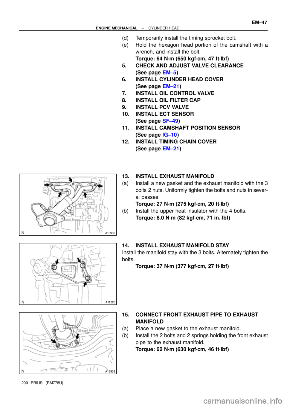
13. INSTALL EXHAUST MANIFOLD
(a) Install a new gasket and the exhaust manifold with the 3
bolts 2 nuts. Uniformly tighten the bolts and nuts in sever-
al passes.
Torque: 27 N´m (275 kgf´cm, 20 ft´lbf)
(b) Install the upper heat insulator with the 4 bolts.
Torque: 8.0 N´m (82 kgf´cm, 71 in.´lbf)
14. INSTALL EXHAUST MANIFOLD STAY
Install the manifold stay with the 3 bolts. Alternately tighten the
bolts.
Torque: 37 N´m (377 kgf´cm, 27 ft´lbf)
15. CONNECT FRONT EXHAUST PIPE TO EXHAUST
MANIFOLD
(a) Place a new gasket to the exhaust manifold.
(b) Install the 2 bolts and 2 springs holding the front exhaust
pipe to the exhaust manifold.
Torque: 62 N´m (630 kgf´cm, 46 ft´lbf)