Page 1554 of 1943
B11830
A13909
F12396
TOYOTA Hand±Held Tester
DLC3
± SFISFI SYSTEM
SF±5
1219 Author�: Date�:
2001 PRIUS (RM778U)
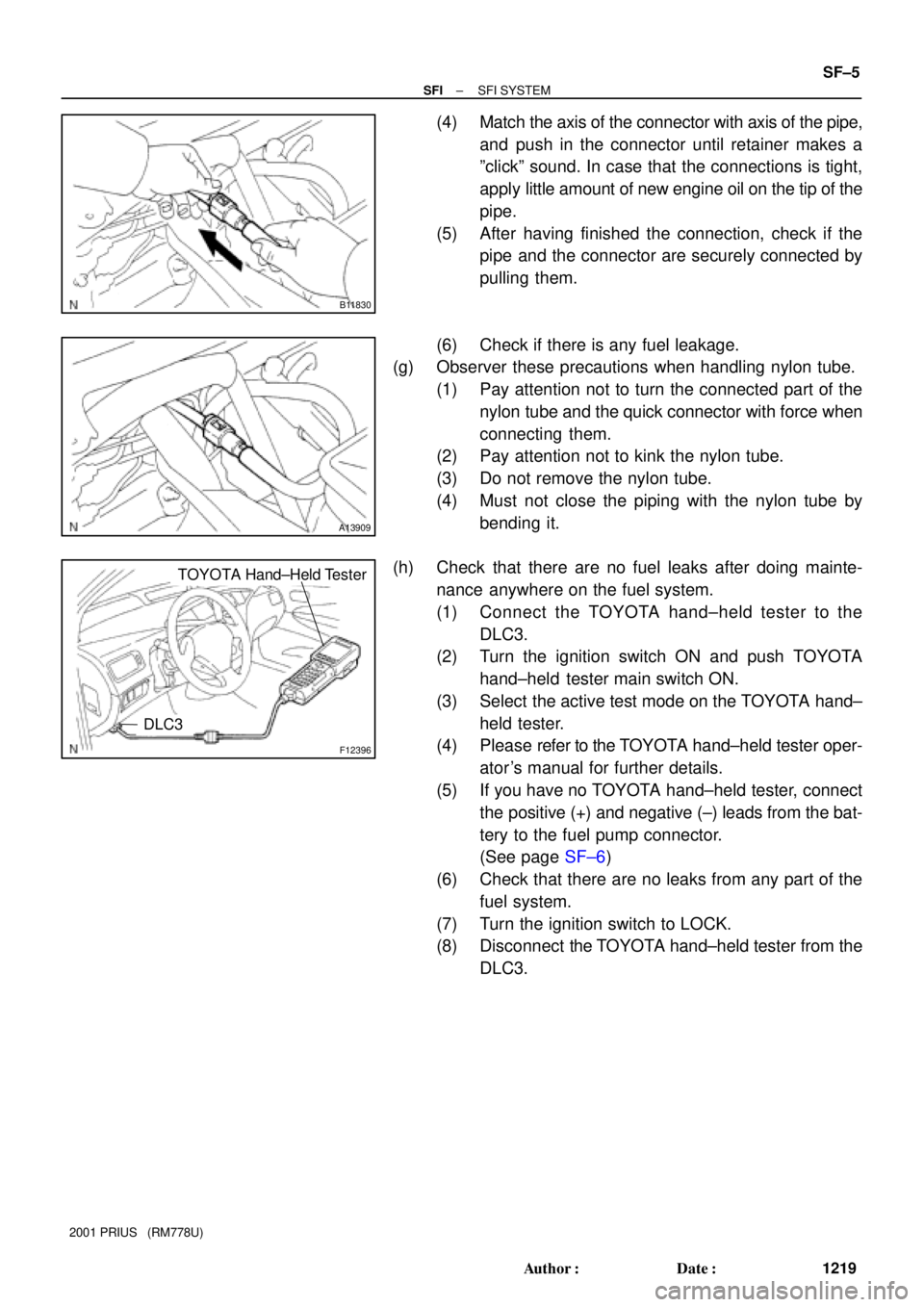
(4) Match the axis of the connector with axis of the pipe,
and push in the connector until retainer makes a
ºclickº sound. In case that the connections is tight,
apply little amount of new engine oil on the tip of the
pipe.
(5) After having finished the connection, check if the
pipe and the connector are securely connected by
pulling them.
(6) Check if there is any fuel leakage.
(g) Observer these precautions when handling nylon tube.
(1) Pay attention not to turn the connected part of the
nylon tube and the quick connector with force when
connecting them.
(2) Pay attention not to kink the nylon tube.
(3) Do not remove the nylon tube.
(4) Must not close the piping with the nylon tube by
bending it.
(h) Check that there are no fuel leaks after doing mainte-
nance anywhere on the fuel system.
(1) Connect the TOYOTA hand±held tester to the
DLC3.
(2) Turn the ignition switch ON and push TOYOTA
hand±held tester main switch ON.
(3) Select the active test mode on the TOYOTA hand±
held tester.
(4) Please refer to the TOYOTA hand±held tester oper-
ator 's manual for further details.
(5) If you have no TOYOTA hand±held tester, connect
the positive (+) and negative (±) leads from the bat-
tery to the fuel pump connector.
(See page SF±6)
(6) Check that there are no leaks from any part of the
fuel system.
(7) Turn the ignition switch to LOCK.
(8) Disconnect the TOYOTA hand±held tester from the
DLC3.
Page 1555 of 1943
F12396
TOYOTA Hand±Held Tester
DLC3
SF1KO±01
B11794
7
3
Battery
B11816
B09225
Fuel Tube Connector
SF±6
± SFIFUEL PUMP
1220 Author�: Date�:
2001 PRIUS (RM778U)
FUEL PUMP
ON±VEHICLE INSPECTION
1. CHECK FUEL PUMP OPERATION
(a) Connect the TOYOTA hand±held tester to the DLC3.
(b) Turn the ignition switch ON and TOYOTA hand±held tes-
ter main switch ON.
NOTICE:
Do not start the engine.
(c) Select the active test mode on the TOYOTA hand±held
tester.
(d) Please refer to the TOYOTA hand±held tester operator's
manual for further details.
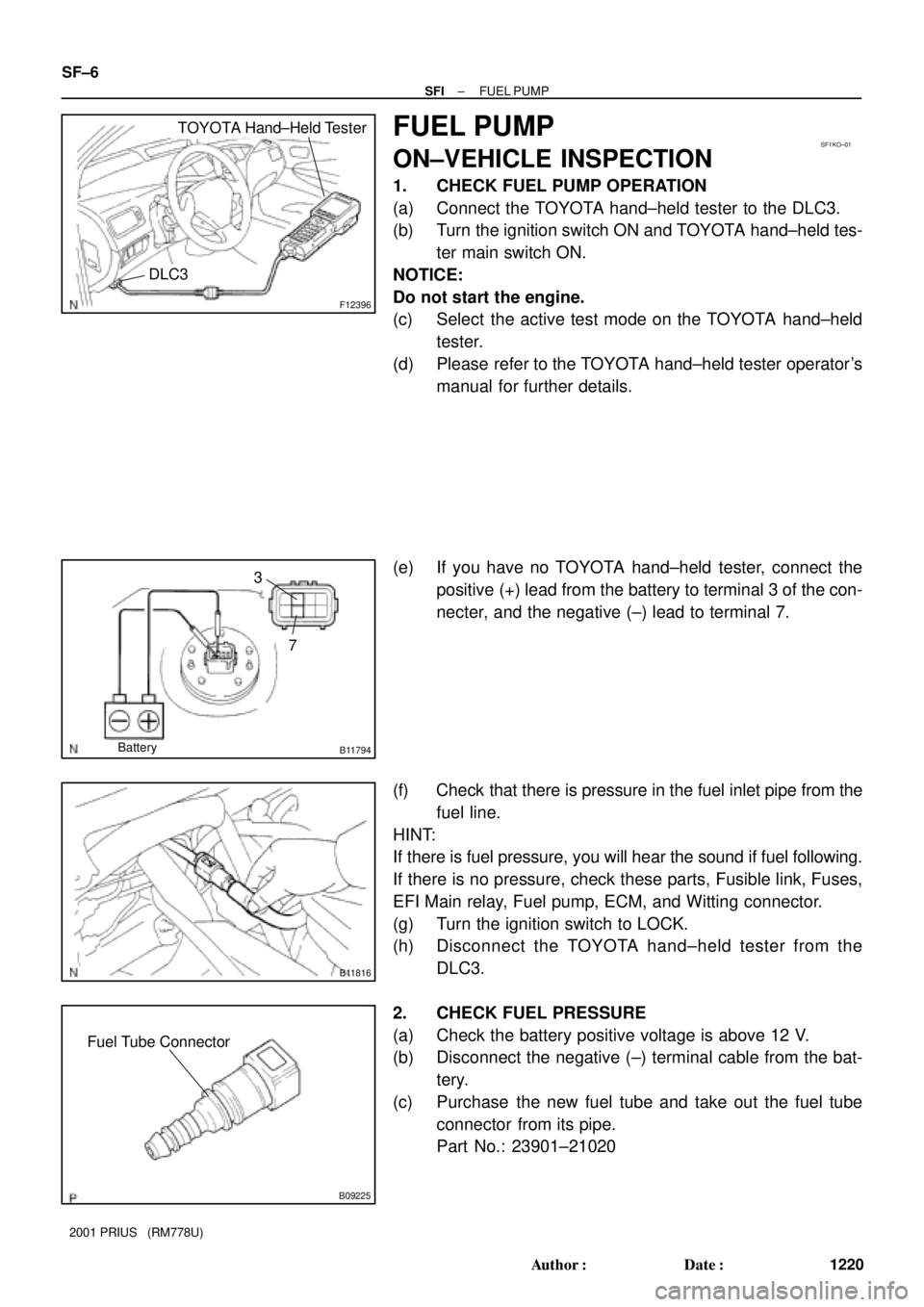
(e) If you have no TOYOTA hand±held tester, connect the
positive (+) lead from the battery to terminal 3 of the con-
necter, and the negative (±) lead to terminal 7.
(f) Check that there is pressure in the fuel inlet pipe from the
fuel line.
HINT:
If there is fuel pressure, you will hear the sound if fuel following.
If there is no pressure, check these parts, Fusible link, Fuses,
EFI Main relay, Fuel pump, ECM, and Witting connector.
(g) Turn the ignition switch to LOCK.
(h) Disconnect the TOYOTA hand±held tester from the
DLC3.
2. CHECK FUEL PRESSURE
(a) Check the battery positive voltage is above 12 V.
(b) Disconnect the negative (±) terminal cable from the bat-
tery.
(c) Purchase the new fuel tube and take out the fuel tube
connector from its pipe.
Part No.: 23901±21020
Page 1556 of 1943
B11815
B00194
SST
SST
(Hose)
Retainer
Fuel pipe
SST
(Hose)
SST
(Hose)
SST
Fuel Tube
Connection
B11794
7
3
Battery
± SFIFUEL PUMP
SF±7
1221 Author�: Date�:
2001 PRIUS (RM778U)
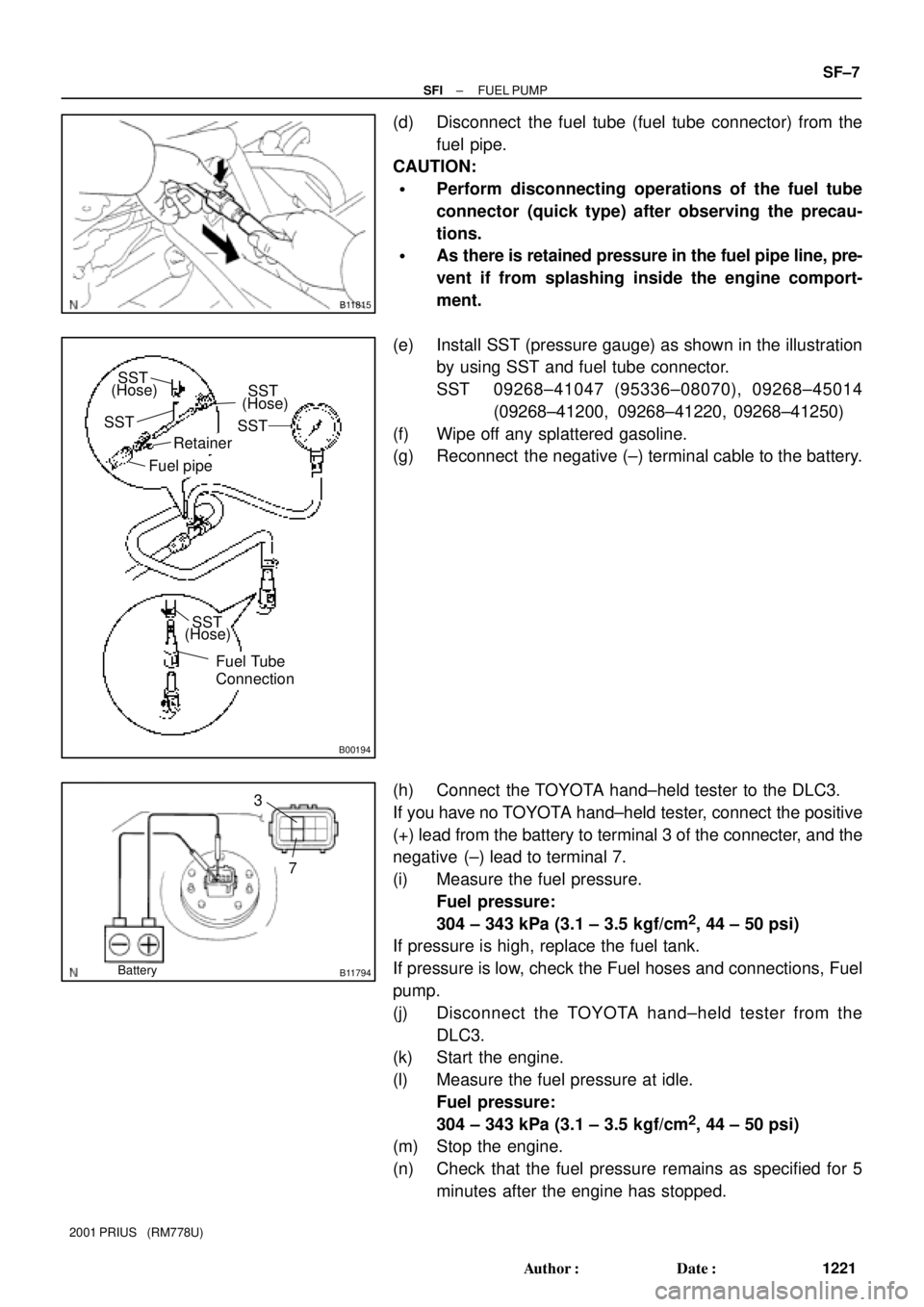
(d) Disconnect the fuel tube (fuel tube connector) from the
fuel pipe.
CAUTION:
�Perform disconnecting operations of the fuel tube
connector (quick type) after observing the precau-
tions.
�As there is retained pressure in the fuel pipe line, pre-
vent if from splashing inside the engine comport-
ment.
(e) Install SST (pressure gauge) as shown in the illustration
by using SST and fuel tube connector.
SST 09268±41047 (95336±08070), 09268±45014
(09268±41200, 09268±41220, 09268±41250)
(f) Wipe off any splattered gasoline.
(g) Reconnect the negative (±) terminal cable to the battery.
(h) Connect the TOYOTA hand±held tester to the DLC3.
If you have no TOYOTA hand±held tester, connect the positive
(+) lead from the battery to terminal 3 of the connecter, and the
negative (±) lead to terminal 7.
(i) Measure the fuel pressure.
Fuel pressure:
304 ± 343 kPa (3.1 ± 3.5 kgf/cm
2, 44 ± 50 psi)
If pressure is high, replace the fuel tank.
If pressure is low, check the Fuel hoses and connections, Fuel
pump.
(j) Disconnect the TOYOTA hand±held tester from the
DLC3.
(k) Start the engine.
(l) Measure the fuel pressure at idle.
Fuel pressure:
304 ± 343 kPa (3.1 ± 3.5 kgf/cm
2, 44 ± 50 psi)
(m) Stop the engine.
(n) Check that the fuel pressure remains as specified for 5
minutes after the engine has stopped.
Page 1559 of 1943
B00416
SST
(Wire)
Battery
B00069
± SFIINJECTOR
SF±13
2001 PRIUS (RM778U)
(j) If you have no TOYOTA hand±held tester, connect the
positive (+) and negative (±) leads from the battery to the
fuel pump connector (See page SF±9).
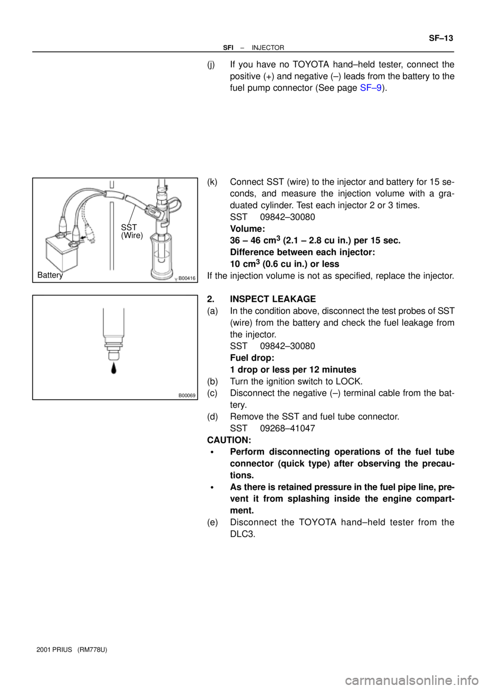
(k) Connect SST (wire) to the injector and battery for 15 se-
conds, and measure the injection volume with a gra-
duated cylinder. Test each injector 2 or 3 times.
SST 09842±30080
Volume:
36 ± 46 cm
3 (2.1 ± 2.8 cu in.) per 15 sec.
Difference between each injector:
10 cm
3 (0.6 cu in.) or less
If the injection volume is not as specified, replace the injector.
2. INSPECT LEAKAGE
(a) In the condition above, disconnect the test probes of SST
(wire) from the battery and check the fuel leakage from
the injector.
SST 09842±30080
Fuel drop:
1 drop or less per 12 minutes
(b) Turn the ignition switch to LOCK.
(c) Disconnect the negative (±) terminal cable from the bat-
tery.
(d) Remove the SST and fuel tube connector.
SST 09268±41047
CAUTION:
�Perform disconnecting operations of the fuel tube
connector (quick type) after observing the precau-
tions.
�As there is retained pressure in the fuel pipe line, pre-
vent it from splashing inside the engine compart-
ment.
(e) Disconnect the TOYOTA hand±held tester from the
DLC3.
Page 1564 of 1943
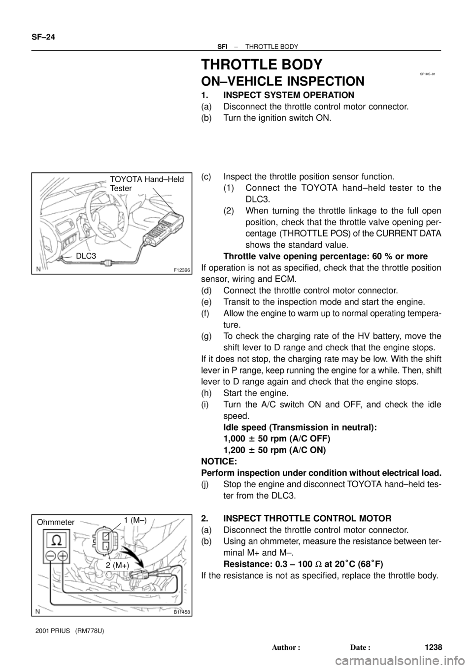
SF1KS±01
F12396
TOYOTA Hand±Held
Tester
DLC3
B11458
Ohmmeter1 (M±)
2 (M+)
SF±24
± SFITHROTTLE BODY
1238 Author�: Date�:
2001 PRIUS (RM778U)
THROTTLE BODY
ON±VEHICLE INSPECTION
1. INSPECT SYSTEM OPERATION
(a) Disconnect the throttle control motor connector.
(b) Turn the ignition switch ON.
(c) Inspect the throttle position sensor function.
(1) Connect the TOYOTA hand±held tester to the
DLC3.
(2) When turning the throttle linkage to the full open
position, check that the throttle valve opening per-
centage (THROTTLE POS) of the CURRENT DATA
shows the standard value.
Throttle valve opening percentage: 60 % or more
If operation is not as specified, check that the throttle position
sensor, wiring and ECM.
(d) Connect the throttle control motor connector.
(e) Transit to the inspection mode and start the engine.
(f) Allow the engine to warm up to normal operating tempera-
ture.
(g) To check the charging rate of the HV battery, move the
shift lever to D range and check that the engine stops.
If it does not stop, the charging rate may be low. With the shift
lever in P range, keep running the engine for a while. Then, shift
lever to D range again and check that the engine stops.
(h) Start the engine.
(i) Turn the A/C switch ON and OFF, and check the idle
speed.
Idle speed (Transmission in neutral):
1,000 ± 50 rpm (A/C OFF)
1,200 ± 50 rpm (A/C ON)
NOTICE:
Perform inspection under condition without electrical load.
(j) Stop the engine and disconnect TOYOTA hand±held tes-
ter from the DLC3.
2. INSPECT THROTTLE CONTROL MOTOR
(a) Disconnect the throttle control motor connector.
(b) Using an ohmmeter, measure the resistance between ter-
minal M+ and M±.
Resistance: 0.3 ± 100 W at 20°C (68°F)
If the resistance is not as specified, replace the throttle body.
Page 1573 of 1943
± COOLINGCOOLANT
CO±3
2001 PRIUS (RM778U)
(f) Remove the radiator cap and check the engine coolant
level of the radiator. If it has dropped, repeat steps (d) to
(g).
(g) Bleed air from water pump.
Set the vehicle in the following conditions:
�Ignition switch ON
�Blower speed control dial to LO
�Temperature control dial to MAX. HOT
(h) Operate the water pump in the following conditions:
�The engine stopped
�The blower switch ON
�Temperature control dial at MAX. HOT
HINT:
Operate the water pump until a sound of the air±containing en-
gine coolant can not be heard from the heater core.
(i) When the engine coolant remains full, fill the radiator res-
ervoir tank with engine coolant to the maximum level.
3. CHECK FOR COOLANT LEAKS
4. CHECK ENGINE COOLANT SPECIFIC GRAVITY IS
CORRECT
Page 1574 of 1943
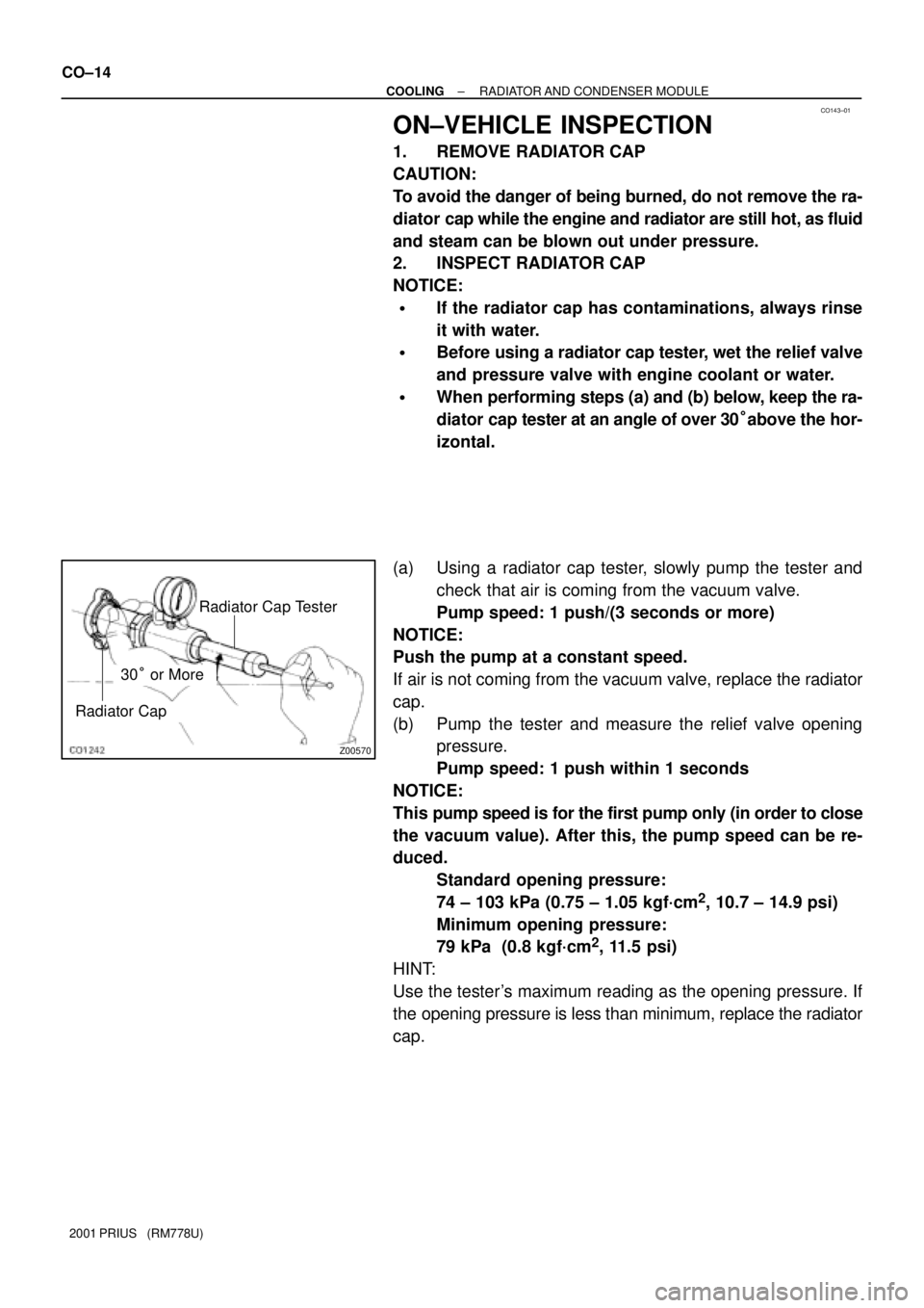
CO143±01
Z00570
Radiator Cap Tester
Radiator Cap
30° or More CO±14
± COOLINGRADIATOR AND CONDENSER MODULE
2001 PRIUS (RM778U)
ON±VEHICLE INSPECTION
1. REMOVE RADIATOR CAP
CAUTION:
To avoid the danger of being burned, do not remove the ra-
diator cap while the engine and radiator are still hot, as fluid
and steam can be blown out under pressure.
2. INSPECT RADIATOR CAP
NOTICE:
�If the radiator cap has contaminations, always rinse
it with water.
�Before using a radiator cap tester, wet the relief valve
and pressure valve with engine coolant or water.
�When performing steps (a) and (b) below, keep the ra-
diator cap tester at an angle of over 30°above the hor-
izontal.
(a) Using a radiator cap tester, slowly pump the tester and
check that air is coming from the vacuum valve.
Pump speed: 1 push/(3 seconds or more)
NOTICE:
Push the pump at a constant speed.
If air is not coming from the vacuum valve, replace the radiator
cap.
(b) Pump the tester and measure the relief valve opening
pressure.
Pump speed: 1 push within 1 seconds
NOTICE:
This pump speed is for the first pump only (in order to close
the vacuum value). After this, the pump speed can be re-
duced.
Standard opening pressure:
74 ± 103 kPa (0.75 ± 1.05 kgf´cm
2, 10.7 ± 14.9 psi)
Minimum opening pressure:
79 kPa (0.8 kgf´cm
2, 11.5 psi)
HINT:
Use the tester's maximum reading as the opening pressure. If
the opening pressure is less than minimum, replace the radiator
cap.
Page 1575 of 1943
B11773
Radiator Cap Tester
± COOLINGRADIATOR AND CONDENSER MODULE
CO±15
2001 PRIUS (RM778U)
3. INSPECT COOLING SYSTEM FOR LEAKS
(a) Fill the radiator with coolant and attach a radiator cap tes-
ter.
(b) Warm up the engine.
(c) Pump it to 118 kPa (1.2 kgf´cm
2, 17.1 psi), and check that
the pressure drops.
If the pressure drops, check the hoses, radiator or water pump
for leaks. If no external leaks are found, check the heater core,
cylinder block and head.
4. REINSTALL RADIATOR CAP