Page 1520 of 2572
B51581
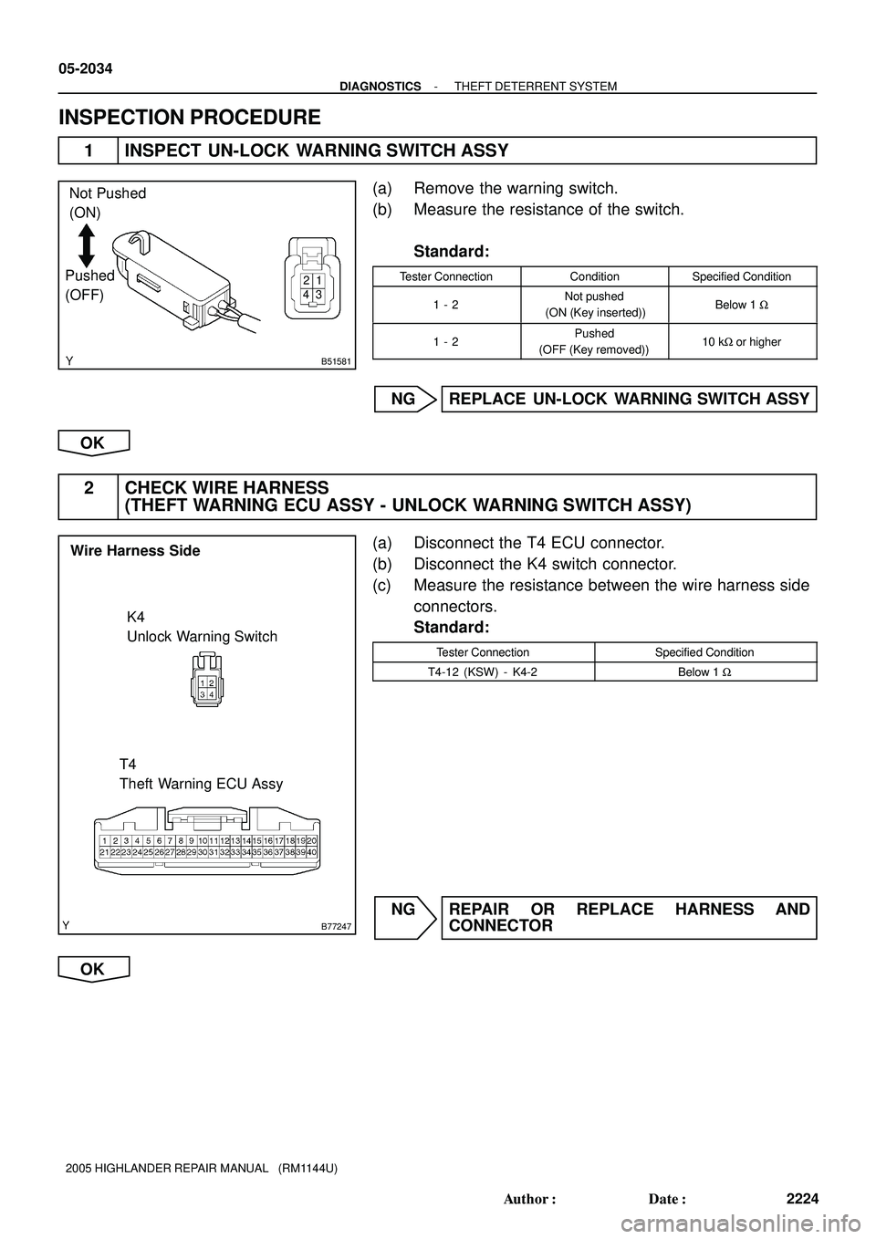
Not Pushed
(ON)
Pushed
(OFF)
21
3 4
B77247
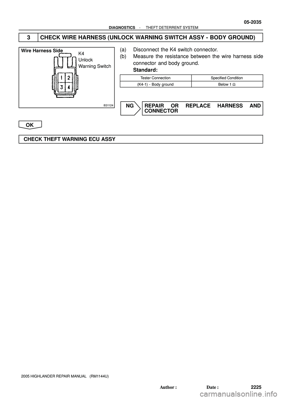
Wire Harness Side
K4
Unlock Warning Switch
T4
Theft Warning ECU Assy
05-2034
- DIAGNOSTICSTHEFT DETERRENT SYSTEM
2224 Author�: Date�:
2005 HIGHLANDER REPAIR MANUAL (RM1144U)
INSPECTION PROCEDURE
1 INSPECT UN-LOCK WARNING SWITCH ASSY
(a) Remove the warning switch.
(b) Measure the resistance of the switch.
Standard:
Tester ConnectionConditionSpecified Condition
1 - 2Not pushed
(ON (Key inserted))Below 1 W
1 - 2Pushed
(OFF (Key removed))10 kW or higher
NG REPLACE UN-LOCK WARNING SWITCH ASSY
OK
2 CHECK WIRE HARNESS
(THEFT WARNING ECU ASSY - UNLOCK WARNING SWITCH ASSY)
(a) Disconnect the T4 ECU connector.
(b) Disconnect the K4 switch connector.
(c) Measure the resistance between the wire harness side
connectors.
Standard:
Tester ConnectionSpecified Condition
T4-12 (KSW) - K4-2Below 1 W
NG REPAIR OR REPLACE HARNESS AND
CONNECTOR
OK
Page 1521 of 2572
B31124
Wire Harness Side
K4
Unlock
Warning Switch
- DIAGNOSTICSTHEFT DETERRENT SYSTEM
05-2035
2225 Author�: Date�:
2005 HIGHLANDER REPAIR MANUAL (RM1144U)
3 CHECK WIRE HARNESS (UNLOCK WARNING SWITCH ASSY - BODY GROUND)
(a) Disconnect the K4 switch connector.
(b) Measure the resistance between the wire harness side
connector and body ground.
Standard:
Tester ConnectionSpecified Condition
(K4-1) - Body groundBelow 1 W
NG REPAIR OR REPLACE HARNESS AND
CONNECTOR
OK
CHECK THEFT WARNING ECU ASSY
Page 1561 of 2572

2 READ VALUE OF HAND-HELD TESTER")
I30899
Fuel Sender Gauge
Connector Front View:
I39224
F
EWarning
05-1894
- DIAGNOSTICSCOMBINATION METER
2084 Author�: Date�:
2005 HIGHLANDER REPAIR MANUAL (RM1144U)
2 READ VALUE OF HAND-HELD TESTER(FUEL GAUGE)
(a) Operate the hand-held tester according to the steps on the display and select the ºDATA LISTº.
METER:
ItemMeasurement Item/
Range (Display)Normal ConditionDiagnostic Note
FUEL GAUGEFuel input signal
Min.: 0, Max.: 255
Fuel gauge indicates (F): 48
Fuel gauge indicates (3/4): 93
Fuel gauge indicates (1/2): 148
Fuel gauge indicates (1/4): 188
Fuel gauge indicates (E): 206
-
OK:
Fuel input signal displayed on the tester is almost the same as Needle indication.
NG Go to step 3
OK
REPLACE COMBINATION METER ASSY(SEE PAGE 71-18)
3 INSPECT FUEL SENDER GAUGE ASSY
(a) Measure the voltage according to the value(s) in the table
below.
Standard:
Tester ConnectionConditionSpecified Condition
F20-1 - F20-3Ignition switch ACC or ONBelow 1 to 5 V
(b) Remove the fuel sender gauge assy.
(c) Connect the fuel sender gauge connector.
(d) Check that the float position is between E and F.
(e) Measure the voltage between the terminals 2 and 1 of
connector according to the value(s) in the table below.
Standard:
Float levelFloat position mm (in.)Voltage (V)
F-34.8 (-1.37) � 3 (0.12)4.5 to 4.75
1/292.8 (3.65) � 3 (0.12)1.41 � 1.61
Warning137.0 (5.39) � 3 (0.12)0.20 to 0.45
NG REPLACE FUEL SENDER GAUGE ASSY
OK
Page 2018 of 2572

H45941
Airbag Sensor
Assy Center
A175
E1 E2
27IG2
1
Battery28 7IGN Instrument Panel J/B
IG2
6 YAM2
GR
1LB
A17
A17 1C
IAW-B
W-B W-B14
9
1L 1L
1D L-Y 1
IC1
FL MAINW F7 FL Block
WI15
Ignition SW
Instrument Panel J/BAM2
10
1 16
- DIAGNOSTICSSUPPLEMENTAL RESTRAINT SYSTEM
05-1515
1705 Author�: Date�:
2005 HIGHLANDER REPAIR MANUAL (RM1144U)
SOURCE VOLTAGE DROP
CIRCUIT DESCRIPTION
The SRS is equipped with a voltage-increase circuit (DC-DC converter) in the airbag sensor assy center
in case the source voltage drops.
When the battery voltage drops, the voltage-increase circuit (DC-DC converter) functions to increase the
voltage of the SRS to normal voltage.
A malfunction in this circuit is displayed differently from other codes. The source voltage drop is indicated
when the SRS warning light comes on without showing any DTCs.
A malfunction in this circuit is not recorded in the airbag sensor assy center. The SRS warning light automati-
cally goes off when the source voltage returns to normal.
DTC No.Diagnosis
(Normal)Source voltage drop
WIRING DIAGRAM
05267-05
Page 2019 of 2572

INSPECTION PROCEDURE
1 CHECK SOURCE VOLTAGE
(a) Turn the ignition")
H40065
A17 IG2
E2
E1
05-1516
- DIAGNOSTICSSUPPLEMENTAL RESTRAINT SYSTEM
1706 Author�: Date�:
2005 HIGHLANDER REPAIR MANUAL (RM1144U)
INSPECTION PROCEDURE
1 CHECK SOURCE VOLTAGE
(a) Turn the ignition switch to the LOCK position.
(b) Disconnect the negative (-) terminal cable from the bat-
tery, and wait for at least 90 seconds.
(c) Disconnect the connector of the airbag sensor assy cen-
ter.
(d) Connect the negative (-) terminal cable to the battery,
and wait for at least 2 seconds.
(e) Turn the ignition switch to the ON position.
(f) Measure the voltage and resistance according to the val-
ue(s) in the table below.
Standard:
Tester connectionConditionSpecified condition
A17-5 (IG2) -
Body groundIgnition switch ON10 to 14 V
A17-27 (E1) -
Body groundAlwaysBelow 1 W
A17-28 (E2) -
Body groundAlwaysBelow 1 W
NG REPAIR OR REPLACE WIRE HARNESS
(BATTERY - AIRBAG SENSOR ASSY CENTER),
CHARGING SYSTEM AND BATTERY
OK
2 CHECK SRS WARNING LIGHT
(a) Turn the ignition switch to the LOCK position.
(b) Disconnect the negative (-) terminal cable from the battery, and wait for at least 90 seconds.
(c) Connect the airbag sensor assy center connectors.
(d) Connect the negative (-) terminal cable to the battery, and wait for at least 2 seconds.
(e) Turn the ignition switch to the ON position.
(f) Operate all components of the electrical system (defogger, wiper, headlight, heater blower, etc.) and
check the SRS warning light operation.
OK:
SRS warning light does not come on.
NG REPLACE AIR BAG SENSOR ASSY CENTER
(SEE PAGE 60-53)
OK
END
Page 2020 of 2572
- DIAGNOSTICSSUPPLEMENTAL RESTRAINT SYSTEM
05-1517
1707 Author�: Date�:
2005 HIGHLANDER REPAIR MANUAL (RM1144U)
SRS WARNING LIGHT CIRCUIT MALFUNCTION (ALWAYS LIGHT
UP, WHEN DTC IS NOT OUTPUT.)
CIRCUIT DESCRIPTION
The SRS warning light is located on the combination meter.
When the SRS is normal, the SRS warning light lights up for approx. 6 seconds after the ignition switch is
turned from the LOCK position to ON position, and then turns off automatically.
If there is a malfunction in the SRS, the SRS warning light lights up to inform the driver of the abnormality.
When terminals Tc and CG of the DLC3 are connected, the DTC is displayed by blinking the SRS warning
light.
05IX2-02
Page 2024 of 2572

SRS WARNING LIGHT CIRCUIT MALFUNCTION (DOES NOT LIGHT
UP, WHEN IGNITION SWITCH IS TURN")
- DIAGNOSTICSSUPPLEMENTAL RESTRAINT SYSTEM
05-1521
1711 Author�: Date�:
2005 HIGHLANDER REPAIR MANUAL (RM1144U)
SRS WARNING LIGHT CIRCUIT MALFUNCTION (DOES NOT LIGHT
UP, WHEN IGNITION SWITCH IS TURNED TO ON)
CIRCUIT DESCRIPTION
The SRS warning light is located on the combination meter.
When the SRS is normal, the SRS warning light lights up for approx. 6 seconds after the ignition switch is
turned from the LOCK position to ON position, and then turns off automatically.
If there is a malfunction is the SRS, the SRS warning light lights up to inform the driver of the abnormality.
When terminals Tc and CG of the DLC3 are connected, the DTC is displayed by blinking the SRS warning
light.
WIRING DIAGRAM
see page 05-1517.
INSPECTION PROCEDURE
1 CHECK BATTERY
(a) Measure the voltage of the battery.
Standard: 11 to 14 V
NG REPLACE BATTERY
OK
2 CHECK WIRE HARNESS
(a) Turn the ignition switch to the LOCK position.
(b) Disconnect the negative (-) terminal cable from the battery, and wait for at least 90 seconds.
(c) Disconnect the connector from the airbag sensor assy center.
(d) Connect the negative (-) terminal cable from the battery, and wait for at least 2 seconds.
(e) Turn the ignition switch to the ON position.
(f) Measure the resistance according to the value(s) in the table below.
OK:
The SRS warning light comes on.
NG REPAIR OR REPLACE WIRE HARNESS
(COMBINATION METER - BATTERY)
OK
REPLACE COMBINATION METER ASSEMBLY (SEE PAGE 71-10)
05269-04
Page 2039 of 2572
05CLA-03
F46769
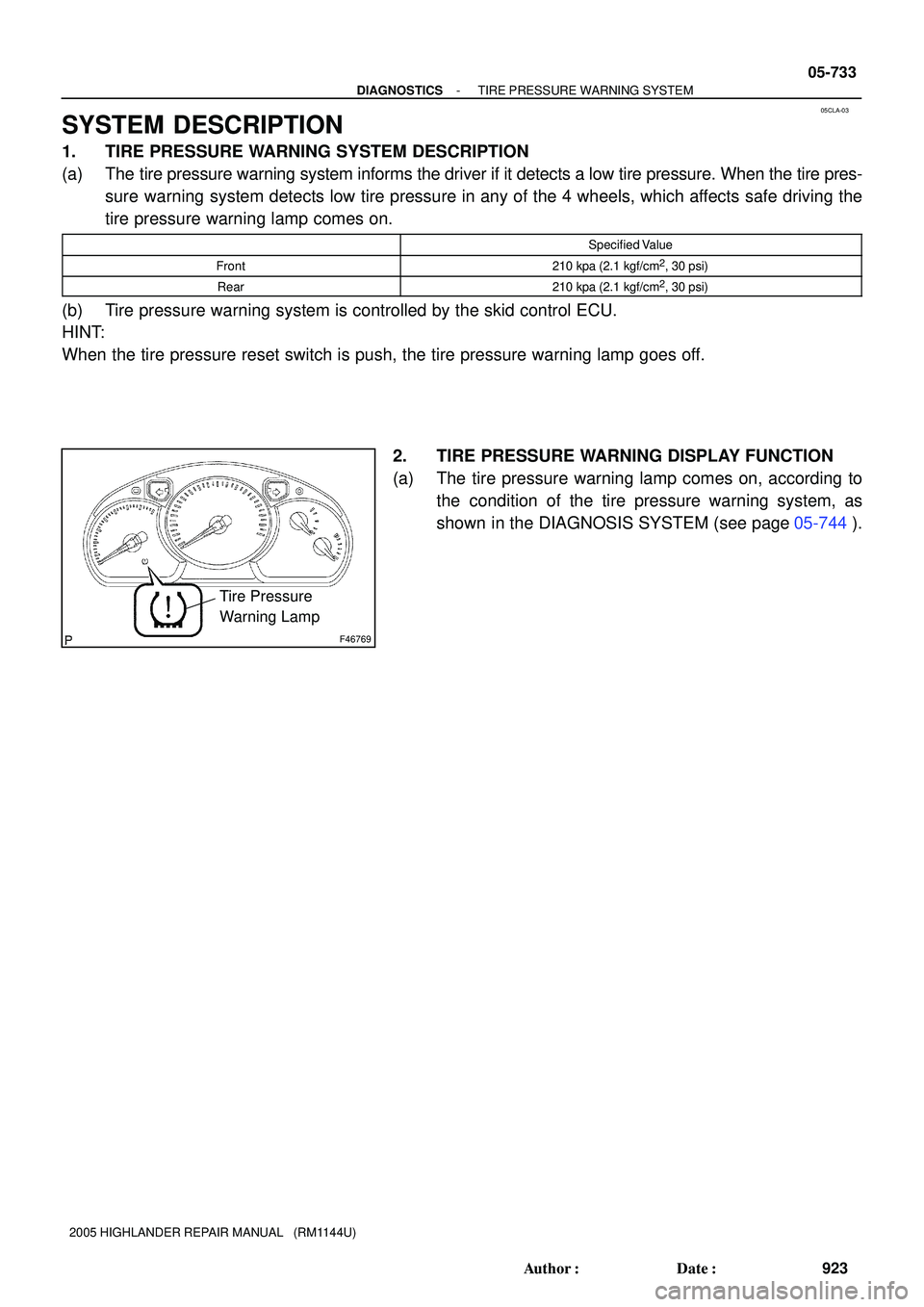
Tire Pressure
Warning Lamp
- DIAGNOSTICSTIRE PRESSURE WARNING SYSTEM
05-733
923 Author�: Date�:
2005 HIGHLANDER REPAIR MANUAL (RM1144U)
SYSTEM DESCRIPTION
1. TIRE PRESSURE WARNING SYSTEM DESCRIPTION
(a) The tire pressure warning system informs the driver if it detects a low tire pressure. When the tire pres-
sure warning system detects low tire pressure in any of the 4 wheels, which affects safe driving the
tire pressure warning lamp comes on.
Specified Value
Front210 kpa (2.1 kgf/cm2, 30 psi)
Rear210 kpa (2.1 kgf/cm2, 30 psi)
(b) Tire pressure warning system is controlled by the skid control ECU.
HINT:
When the tire pressure reset switch is push, the tire pressure warning lamp goes off.
2. TIRE PRESSURE WARNING DISPLAY FUNCTION
(a) The tire pressure warning lamp comes on, according to
the condition of the tire pressure warning system, as
shown in the DIAGNOSIS SYSTEM (see page 05-744).