Page 1256 of 2572
B50657
T4
- DIAGNOSTICSMULTIPLEX COMMUNICATION SYSTEM
05-2079
2269 Author�: Date�:
2005 HIGHLANDER REPAIR MANUAL (RM1144U)
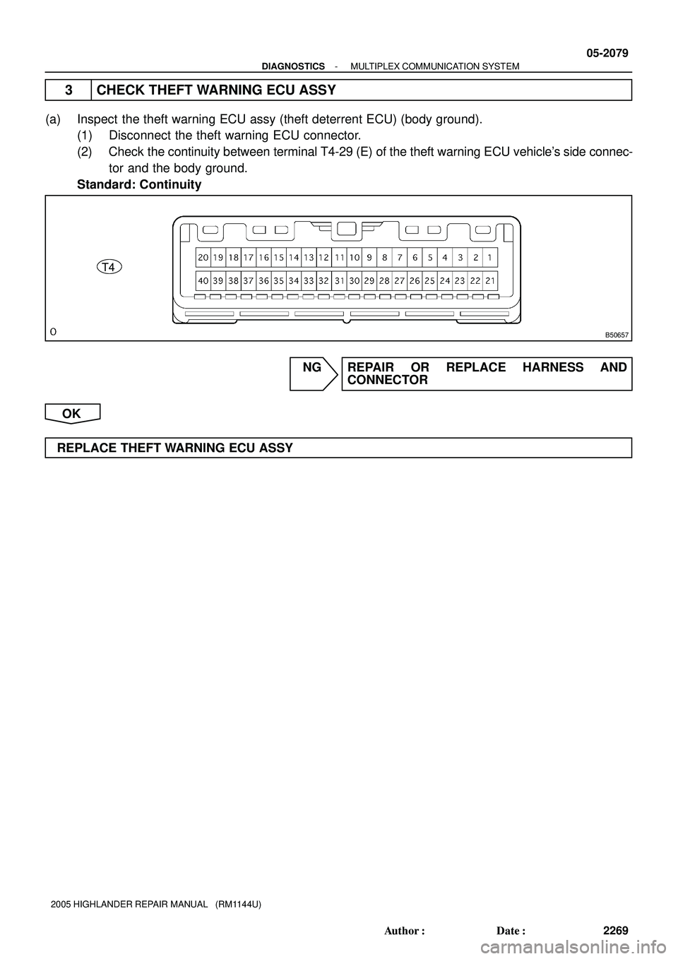
3 CHECK THEFT WARNING ECU ASSY
(a) Inspect the theft warning ECU assy (theft deterrent ECU) (body ground).
(1) Disconnect the theft warning ECU connector.
(2) Check the continuity between terminal T4-29 (E) of the theft warning ECU vehicle's side connec-
tor and the body ground.
Standard: Continuity
NG REPAIR OR REPLACE HARNESS AND
CONNECTOR
OK
REPLACE THEFT WARNING ECU ASSY
Page 1302 of 2572
B51271
9
BG3
4
BG2Y
LGLOCK
UNLOCK
B14
Back Door Key Lock
and Unlock Switch
IA214
4 V
B
J14
J/C17
1
T4L Theft Warning ECU Assy
IL2
8
IL2UL 33T415
IA2
BRSB
BR
Y 2
3
BE W-B
A
I07296
LOCK
UNLOCK
05-2036
- DIAGNOSTICSTHEFT DETERRENT SYSTEM
2226 Author�: Date�:
2005 HIGHLANDER REPAIR MANUAL (RM1144U)
BACK DOOR KEY LOCK AND UNLOCK SWITCH CIRCUIT
CIRCUIT DESCRIPTION
The back door key lock and unlock switch comes on when the back door key cylinder is turned to the unlock
side with the key.
WIRING DIAGRAM
INSPECTION PROCEDURE
1 CHECK BACK DOOR KEY LOCK AND UNLOCK SWITCH
(a) Remove the switch.
(b) Measure the resistance.
Standard:
Tester ConnectionConditionSpecified Condition
1-2Turned to lock sideBelow 1 W
1-2, 1-3Not turned10 kW or higher
1-3Turned to unlock sideBelow 1 W
NG REPLACE BACK DOOR KEY LOCK AND
UNLOCK SWITCH
OK
05ITO-02
Page 1303 of 2572

B77251
Wire Harness Side
B14
Back Door Key
Lock and Unlock Switch
T4
Theft Warning ECU Assy
B31046
Wire Harness Side
B14
Back Door Key Lock and Unlock Switch
- DIAGNOSTICSTHEFT DETERRENT SYSTEM
05-2037
2227 Author�: Date�:
2005 HIGHLANDER REPAIR MANUAL (RM1144U)
2 CHECK WIRE HARNESS
(THEFT WARNING ECU ASSY - BACK DOOR KEY LOCK AND UNLOCK SWITCH)
(a) Disconnect the T4 ECU connector.
(b) Disconnect the B14 switch connector.
(c) Measure the resistance between the wire harness side
connectors.
Standard:
Tester ConnectionSpecified Condition
B14-2 (LOCK) - T4-15 (L)Below 1 W
B14-8 (UNLOCK) - T4-33 (UL)Below 1 W
NG REPAIR OR REPLACE HARNESS AND
CONNECTOR
OK
3 CHECK BACK DOOR KEY LOCK AND UNLOCK SWITCH (BODY GROUND)
(a) Disconnect the B14 switch connector.
(b) Measure the resistance between the wire harness side
connector and body ground.
Standard:
Tester ConnectionSpecified Condition
B14-1 - Body groundBelow 1 W
NG REPAIR OR REPLACE HARNESS AND
CONNECTOR
OK
REPLACE THEFT WARNING ECU ASSY
Page 1335 of 2572
B80399
D.C.C
BatteryTheft Warning ECU Assy
+B1
E 29
13 5
3D 2A 4
3F
W-B 1W-B IC35
BR
FL Main 3Instrument Panel J/B Assy
Engine Room
J/B Assy
Center J/B
W ECU-B2A
2I1
SECURITY
5
IB+B2
W4
IC3IF1IL1 11
WL E
E J17
J/C
P
1G 1D
10
9P
2
L2
3 O
W-L
F7
FUSIBLE
LINK BLOCKT4 05-2026
- DIAGNOSTICSTHEFT DETERRENT SYSTEM
2216 Author�: Date�:
2005 HIGHLANDER REPAIR MANUAL (RM1144U)
ECU POWER SOURCE CIRCUIT
CIRCUIT DESCRIPTION
This circuit provides power to operate the theft deterrent (warning) ECU.
WIRING DIAGRAM
0522S-06
Page 1336 of 2572

B63408
Wire Harness Side
T4
Theft Warning ECU Assy
B63408
Wire Harness Side
T4
Theft Warning ECU Assy
- DIAGNOSTICSTHEFT DETERRENT SYSTEM
05-2027
2217 Author�: Date�:
2005 HIGHLANDER REPAIR MANUAL (RM1144U)
INSPECTION PROCEDURE
1 CHECK THEFT WARNING ECU ASSY (ECU-B)
(a) Remove the ECU-B fuse from the engine room J/B.
(b) Measure the resistance.
Standard: Below 1 W
OK PROCEED TO NEXT CIRCUIT INSPECTION
SHOWN IN PROBLEM SYMPTOMS TABLE
NG
2 CHECK WIRE HARNESS (POWER SOURCE)
(a) Disconnect the T4 ECU connector.
(b) Measure the voltage of the wire harness side connector.
Standard:
Tester ConnectionSpecified Condition
T4-2 (+B1) - T4-29 (E)10 to 14 V
NG REPAIR OR REPLACE HARNESS AND
CONNECTOR
OK
3 CHECK THEFT WARNING ECU ASSY (GROUND)
(a) Disconnect the T5 ECU connector.
(b) Measure the resistance between the wire harness side
connector and body ground.
Standard:
Tester ConnectionSpecified Condition
T4-2 (+B1) - Body groundBelow 1 W
T4-29 (E) - Body groundBelow 1 W
NG REPAIR OR REPLACE HARNESS AND
CONNECTOR
OK
PROCEED TO NEXT CIRCUIT INSPECTION
Page 1501 of 2572
B51273
2G E3
Security Courtesy Switch
(Engine Hood Courtesy Switch)
IK315
G-B
J1
J/CT4 Theft Warning ECU Assy
6
IL2DSWH 34
W
EGW-B
1
A
I04148
Not Pushed (ON)
Pushed
(OFF)Security
Courtesy Switch
05-2038
- DIAGNOSTICSTHEFT DETERRENT SYSTEM
2228 Author�: Date�:
2005 HIGHLANDER REPAIR MANUAL (RM1144U)
ENGINE HOOD COURTESY SWITCH CIRCUIT
CIRCUIT DESCRIPTION
The hood door courtesy switch is built in the engine hood lock assembly. The switch comes on when the
engine hood is opened and goes off when the engine hood is closed.
WIRING DIAGRAM
INSPECTION PROCEDURE
1 INSPECT SECURITY COURTESY SWITCH
(a) Remove the courtesy switch.
(b) Measure the resistance of the switch.
Tester ConnectionConditionSpecified Condition
1-2Pushed (OFF (Lock))10 kW or higher
1-2Not pushed (ON (Unlock))Below 1 W
NG REPLACE SECURITY COURTESY SWITCH
OK
05ITP-01
Page 1502 of 2572
B77252
T4
Theft Warning ECU Assy Wire Harness Side
E3
Security Courtesy Switch
B31016
E3
Security Courtesy Switch Wire Harness Side
- DIAGNOSTICSTHEFT DETERRENT SYSTEM
05-2039
2229 Author�: Date�:
2005 HIGHLANDER REPAIR MANUAL (RM1144U)
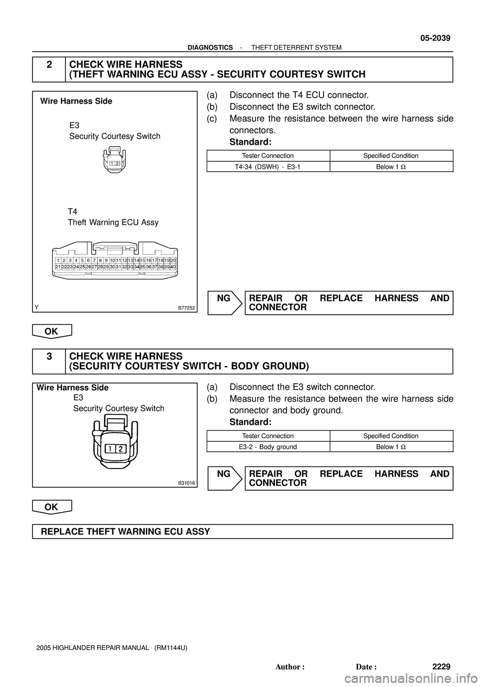
2 CHECK WIRE HARNESS
(THEFT WARNING ECU ASSY - SECURITY COURTESY SWITCH
(a) Disconnect the T4 ECU connector.
(b) Disconnect the E3 switch connector.
(c) Measure the resistance between the wire harness side
connectors.
Standard:
Tester ConnectionSpecified Condition
T4-34 (DSWH) - E3-1Below 1 W
NG REPAIR OR REPLACE HARNESS AND
CONNECTOR
OK
3 CHECK WIRE HARNESS
(SECURITY COURTESY SWITCH - BODY GROUND)
(a) Disconnect the E3 switch connector.
(b) Measure the resistance between the wire harness side
connector and body ground.
Standard:
Tester ConnectionSpecified Condition
E3-2 - Body groundBelow 1 W
NG REPAIR OR REPLACE HARNESS AND
CONNECTOR
OK
REPLACE THEFT WARNING ECU ASSY
Page 1504 of 2572
I40146
LBE-
LBE+A162
A166
A1619
A16113
1 R
G9
MPX+
BEAN
B19
Front Seat Inner Belt Assy (Driver's Side) Airbag Sensor AssemblyC12
Combination Meter Assy
(*2) (*1)
(*2) (*1)
*1: w/o Curtain Shield Airbag
*2: w/ Curtain Shield Airbag
05-1898
- DIAGNOSTICSCOMBINATION METER
2088 Author�: Date�:
2005 HIGHLANDER REPAIR MANUAL (RM1144U)
SEAT BELT WARNING LAMP FOR DRIVER'S SEAT DOES NOT
OPERATE
WIRING DIAGRAM
INSPECTION PROCEDURE
HINT:
If there is an open in the ground circuit (Airbag sensor assy center), the airbag sensor assy center outputs
DTCs. Perform troubleshooting with the ºSupplemental Restraint System 05-1200º.
1 PERFORM ACTIVE TEST BY HAND-HELD TESTER
(a) Operate the hand-held tester according to the steps on the display and select the ºACTIVE TESTº.
METER:
ItemTest DetailsDiagnostic Note
D-BEL T REMINDIndicat. Lamp D-SEAT BELT (OFF/ON)Confirm that the vehicle is stopped and engine
idling
NG REPLACE COMBINATION METER ASSY
(SEE PAGE 71-18)
OK
05IQ1-02


IK315
G-B
J1
J/CT4 Theft Warning ECU Assy
6
IL2DSWH 34
W
EGW-B
1
A
I04148
Not Pushed (ON)
Pushed
(OFF)Security
Courtesy Switch
05-")
 Airbag Sensor AssemblyC12
Combination Meter Assy
(*2) (*1)
(*2) (*1)
*1: w/o Curtain Shield Airba")