Page 1509 of 2572
B65516
1
T5
Security Indicator
Lamp Assy11
13
3F W-B
IB2B
3BTheft Warning ECU Assy
2
IND 3C25 8
T4 R 3F
W-BCenter J/B
B51710
1
2
05-2024
- DIAGNOSTICSTHEFT DETERRENT SYSTEM
2214 Author�: Date�:
2005 HIGHLANDER REPAIR MANUAL (RM1144U)
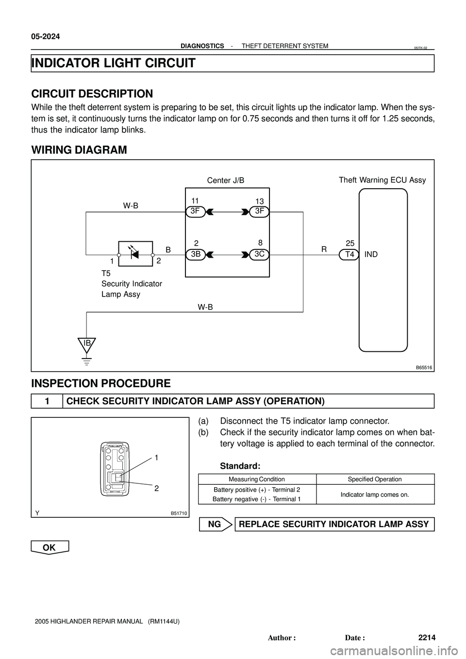
INDICATOR LIGHT CIRCUIT
CIRCUIT DESCRIPTION
While the theft deterrent system is preparing to be set, this circuit lights up the indicator lamp. When the sys-
tem is set, it continuously turns the indicator lamp on for 0.75 seconds and then turns it off for 1.25 seconds,
thus the indicator lamp blinks.
WIRING DIAGRAM
INSPECTION PROCEDURE
1 CHECK SECURITY INDICATOR LAMP ASSY (OPERATION)
(a) Disconnect the T5 indicator lamp connector.
(b) Check if the security indicator lamp comes on when bat-
tery voltage is applied to each terminal of the connector.
Standard:
Measuring ConditionSpecified Operation
Battery positive (+) - Terminal 2
Battery negative (-) - Terminal 1Indicator lamp comes on.
NG REPLACE SECURITY INDICATOR LAMP ASSY
OK
05ITK-02
Page 1510 of 2572
B77249
Wire Harness Side
T5
Security Indicator
Lamp Assy
T4
Theft Warning ECU Assy
B78292
Wire Harness Side
T5
Theft Deterrent
Indicator Lamp Assy
- DIAGNOSTICSTHEFT DETERRENT SYSTEM
05-2025
2215 Author�: Date�:
2005 HIGHLANDER REPAIR MANUAL (RM1144U)
2 CHECK WIRE HARNESS
(THEFT WARNING ECU ASSY - SECURITY INDICATOR LAMP ASSY)
(a) Disconnect the T5 indicator lamp and T4 ECU connectors
(b) Measure the resistance between the wire harness side
connecters.
Standard:
Tester ConnectionSpecified Condition
T4-25 (IND) - T5-2Below 1 W
NG REPAIR OR REPLACE HARNESS AND
CONNECTOR
OK
3 CHECK WIRE HARNESS (SECURITY INDICATOR LAMP ASSY - BODY GROUND)
(a) Disconnect the T5 indicator lamp connector
(b) Measure the resistance between the wire harness side
connector and body ground.
Standard:
Tester ConnectionSpecified Condition
T5-1 - Body groundBelow 1 W
NG REPAIR OR REPLACE HARNESS AND
CONNECTOR
OK
CHECK AND REPLACE THEFT WARNING ECU ASSY
Page 1511 of 2572

05EYX-02
F46772
Tire Pressure
Warning Reset Switch
Tire Pressure
Warning Lamp
Lamp Output Pattern:
� Receipt of the Initialization Signal
Keep pressing
the switch for 3 sec.
1 Sec.
� Failure of Initialization
0.25 Sec.
0.25 Sec. ON
OFF ON
OFF
1 Sec. 3 Sec. 05-736
- DIAGNOSTICSTIRE PRESSURE WARNING SYSTEM
926 Author�: Date�:
2005 HIGHLANDER REPAIR MANUAL (RM1144U)
INITIALIZATION
NOTICE:
�This system requires initializing after changing tires or wheels, or after rotating the tires.
�Be sure to adjust the tire air pressure to the specified value before initialization.
1. INITIALIZING THE TIRE PRESSURE WARNING SYS-
TEM
(a) Check and adjust the tire pressure to the specified value.
Specified Value
Front210 kpa (2.1 kgf/cm2, 30 psi)
Rear210 kpa (2.1 kgf/cm2, 30 psi)
(b) With the vehicle stopped, turn the ignition switch to the
ON position.
(c) Press and hold the tire pressure warning reset switch until
the tire pressure warning lamp blinks 3 times at 1 second
intervals.
HINT:
If the tire pressure warning lamp does not blink, perform the ini-
tialization again. (with the ignition switch off, perform the proce-
dure above starting at step 1-(b).)
(d) Drive the vehicle at 19 mph (30 km/h) or more, to com-
plete the initialization of the skid control ECU. (It takes
more than one hour.)
HINT:
If the tire pressure warning lamp blinks at 0.25 second intervals
while the vehicle is being driven, the initialization may have
failed. If so, perform the initialization again. (Turn the ignition
switch off and retry from step 1-(a).)
(e) After initialization is completed, the skid control ECU mon-
itors the tire pressure by using the wheel speed sensors.
(f) To verify the system has been initialized check the length
of time the tire pressure warning lamp is on after turning
the ignition switch to the ON position.
�Not initialized: 4 sec.
�Initialized: 3 sec.
Page 1514 of 2572

ENGINE IMMOBILIZER SYSTEM
HOW TO PROCEED WITH TROUBLESHOOTING
HINT:
Use this pro")
052IA-27
- DIAGNOSTICSENGINE IMMOBILIZER SYSTEM
05-1985
2175 Author�: Date�:
2005 HIGHLANDER REPAIR MANUAL (RM1144U)
ENGINE IMMOBILIZER SYSTEM
HOW TO PROCEED WITH TROUBLESHOOTING
HINT:
Use this procedure to troubleshoot the engine immobilizer system.
1 VEHICLE BROUGHT TO WORKSHOP
2 CUSTOMER PROBLEM ANALYSIS CHECK AND SYMPTOM CHECK
(see page 05-1987)
3 CRANK ENGINE FOR MORE THAN 10 SECONDS
4 CHECK DTC
(a) Check for DTCs and note any codes that are output.
(b) Delete the DTC.
(c) Recheck for DTCs. Try to prompt the DTC (SFI system and engine immobilizer system) by simulating
the original activity that the DTC suggested.
(1) If the DTC does not reoccur, proceed to A.
(2) If the DTC (SFI system) reoccurs, proceed to B.
(3) If the DTC (engine immobilizer system) reoccur, proceed to C.
B Go to SFI SYSTEM
(2AZ-FE engine: See page 05-1)
(3MZ-FE engine: See page 05-362)
C Go to step 8
A
5 READ VALUE OF HAND-HELD TESTER
(IMMOBILIZER ECU (TRANSPONDER KEY ECU ASSY) (SWITCH CONDITION))
(a) Connect the hand-held tester to the DLC3.
(b) Turn the ignition switch ON and push the hand-held tester main switch ON.
(c) Select the item ºKEY SWº in the ºDATA LISTº and read its value displayed on the hand-held tester.
Transponder key ECU assy:
ItemMeasurement Item/
Display (Range)Normal ConditionDiagnostic Note
KEY SwitchUnlock warning switch signal
/ON or OFFON: Key is in ignition key cylinder
OFF: No key is in ignition key cyl-
inder
-
NG Go to DTC B2780 (see page 05-1998)
Page 1516 of 2572
B78723
KSW
DCTY
MPX1
MPX2 B10
B11
B92
11
6
10 G
B J6
J/C
D
B
B10 D
9
IA1 K4
Un-lock Warning
Switch Assy
1 9
7
14G
Combination Meter Assy
21
C11 Door Open
IndicatorMPX Line D7
Front Door Courtesy
Lamp Switch Assy (Driver Side)2 W-B
4L
4N
9
C12 W-B
W-B
MPX Line IC
YOW SB
MPX+
MPX-1Multiplex Network
Body ECU
Passenger Side J/B
G
- DIAGNOSTICSPOWER DOOR LOCK CONTROL SYSTEM
05-1957
2147 Author�: Date�:
2005 HIGHLANDER REPAIR MANUAL (RM1144U)
KEY CONFINEMENT PREVENTION FUNCTION DOES NOT WORK
PROPERLY (MANUAL OPERATION AND INTERLOCKED WITH
KEY ARE ACTIVE)
CIRCUIT DESCRIPTION
The multiplex network body ECU senses, by the un-lock warning switch, that the ignition key is in the key
cylinder. Because of this, the multiplex network body ECU will unlock all the doors immediately after locking
them if a door has been locked while the key is in the ignition key cylinder.
WIRING DIAGRAM
0526N-02
Page 1517 of 2572
B52271
ON OFF
B61511
B10
05-1958
- DIAGNOSTICSPOWER DOOR LOCK CONTROL SYSTEM
2148 Author�: Date�:
2005 HIGHLANDER REPAIR MANUAL (RM1144U)
INSPECTION PROCEDURE
1 CHECK MANUAL DOOR LOCK OPERATION
NG GO TO POWER WINDOW CONTROL SYSTEM
(See page 05-1912)
OK
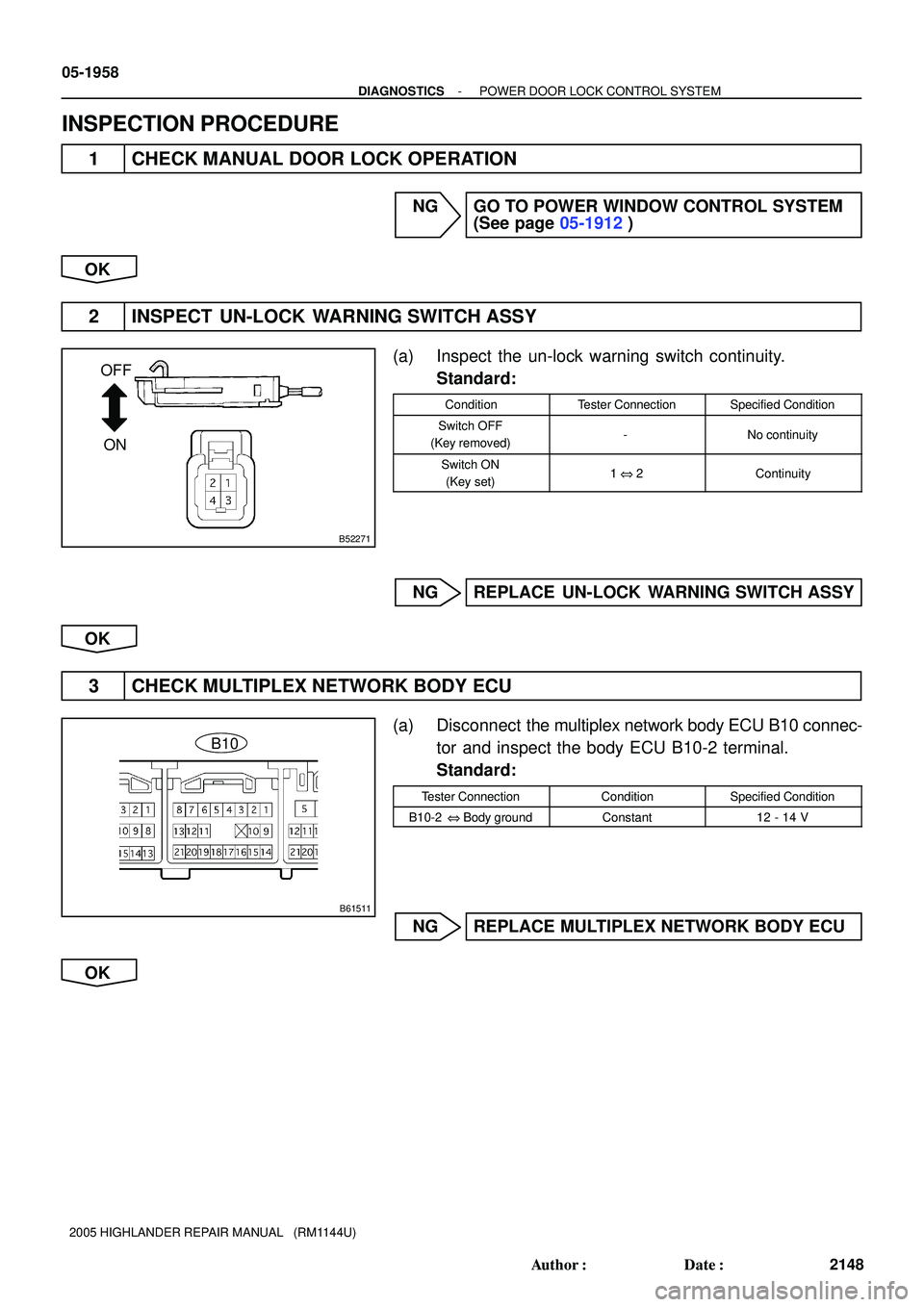
2 INSPECT UN-LOCK WARNING SWITCH ASSY
(a) Inspect the un-lock warning switch continuity.
Standard:
ConditionTester ConnectionSpecified Condition
Switch OFF
(Key removed)-No continuity
Switch ON
(Key set)1 @ 2Continuity
NG REPLACE UN-LOCK WARNING SWITCH ASSY
OK
3 CHECK MULTIPLEX NETWORK BODY ECU
(a) Disconnect the multiplex network body ECU B10 connec-
tor and inspect the body ECU B10-2 terminal.
Standard:
Tester ConnectionConditionSpecified Condition
B10-2 @ Body groundConstant12 - 14 V
NG REPLACE MULTIPLEX NETWORK BODY ECU
OK
Page 1518 of 2572
Wire Harness Side
B51904
- DIAGNOSTICSPOWER DOOR LOCK CONTROL SYSTEM
05-1959
2149 Author�: Date�:
2005 HIGHLANDER REPAIR MANUAL (RM1144U)
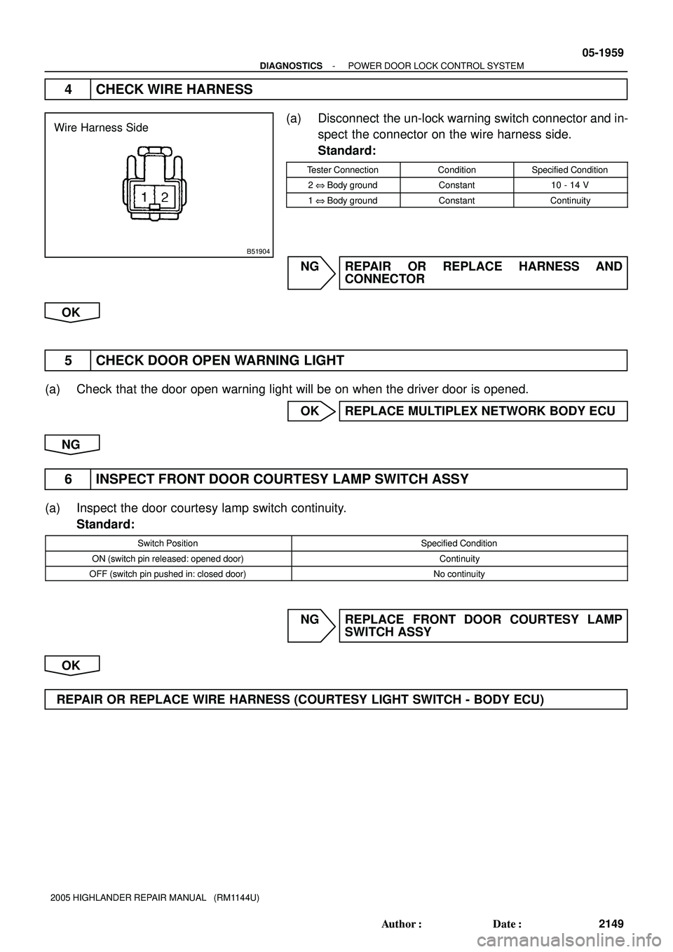
4 CHECK WIRE HARNESS
(a) Disconnect the un-lock warning switch connector and in-
spect the connector on the wire harness side.
Standard:
Tester ConnectionConditionSpecified Condition
2 @ Body groundConstant10 - 14 V
1 @ Body groundConstantContinuity
NG REPAIR OR REPLACE HARNESS AND
CONNECTOR
OK
5 CHECK DOOR OPEN WARNING LIGHT
(a) Check that the door open warning light will be on when the driver door is opened.
OK REPLACE MULTIPLEX NETWORK BODY ECU
NG
6 INSPECT FRONT DOOR COURTESY LAMP SWITCH ASSY
(a) Inspect the door courtesy lamp switch continuity.
Standard:
Switch PositionSpecified Condition
ON (switch pin released: opened door)Continuity
OFF (switch pin pushed in: closed door)No continuity
NG REPLACE FRONT DOOR COURTESY LAMP
SWITCH ASSY
OK
REPAIR OR REPLACE WIRE HARNESS (COURTESY LIGHT SWITCH - BODY ECU)
Page 1519 of 2572
B80391
G K4
Unlock Warning
Switch
1
2 W-B
Body ECUG
KSW DD
D
ICW-B 4L 4G 9
4N12
T4 Theft Warning ECU Assy
J6
J/C
Passenger Side J/BP
IL218
W-B17
- DIAGNOSTICSTHEFT DETERRENT SYSTEM
05-2033
2223 Author�: Date�:
2005 HIGHLANDER REPAIR MANUAL (RM1144U)
UNLOCK WARNING SWITCH CIRCUIT
CIRCUIT DESCRIPTION
The key unlock warning switch comes on when the ignition key is inserted in the ignition key cylinder and
goes off when the ignition key is removed.
The ECU operates the key confinement prevention function while the key unlock warning switch is on.
WIRING DIAGRAM
05ITN-03