Page 834 of 2572

6 CHECK DOOR CONTROL RECEIVER
(")
B51930
Door Control
Receiver
W6 Wire Harness Side
- DIAGNOSTICSWIRELESS DOOR LOCK CONTROL SYSTEM
05-1973
2163 Author�: Date�:
2005 HIGHLANDER REPAIR MANUAL (RM1144U)
6 CHECK DOOR CONTROL RECEIVER
(a) Check the DOME fuse.
(b) Disconnect the W6 receiver connector.
(c) Check the voltage or continuity between the W6 receiver
wire harness side connector and body ground.
Standard:
Terminal No.Specified condition
5 - Body ground10 - 14 V
1 - Body groundContinuity
NG REPAIR OR REPLACE FUSE OR WIRE
HARNESS AND CONNECTOR
OK
REPLACE DOOR CONTROL RECEIVER
7 RE-REGISTER RECOGNITION CODE OF TRANSMITTER
(a) Check if it is possible to enter into the rewrite mode or the add mode for the recognition code registra-
tion, and if a recognition code can be registered, as well.
NG REPLACE MULTIPLEX NETWORK BODY ECU
OK
NORMAL (FUNCTION)
8 CONFIRM INPUT METHOD OF SELF-DIAGNOSTIC MODE
NG Go to step 3
OK
9 INSPECT UN-LOCK WARNING SWITCH ASSY (See page 05-1957)
NG REPLACE UN-LOCK WARNING SWITCH ASSY
OK
REPLACE MULTIPLEX NETWORK BODY ECU
Page 854 of 2572
F46778
ECM S27
Skid Control ECU
With Actuator
A1
A/C Ambient Temp.
SensorENG+
TA M
E2 IC4
IK3V
W-L
E524
Short Connector
S28 EB2ENG-
E5
E6
E7 R
B30
32 IC4
28 5
18
5 W-G
B-R ENG+
ENG-9
23
6
S29 55
BRBRBR
1 2
05-756
- DIAGNOSTICSTIRE PRESSURE WARNING SYSTEM
946 Author�: Date�:
2005 HIGHLANDER REPAIR MANUAL (RM1144U)
AMBIENT TEMPERATURE SENSOR CIRCUIT
CIRCUIT DESCRIPTION
The ambient temperature sensor sends the outside temperature signal to the ECM. The ECM transmits the
signal to the skid control ECU as a communication signal. The skid control ECU controls the tire pressure
warning system, depending on the changes of the outside temperature.
HINT:
The signal sent from the ambient temperature sensor is also used in the A/C.
WIRING DIAGRAM
INSPECTION PROCEDURE
1 CHECK DIAGNOSTIC CODE OUTPUT
(a) Check if the normal code is output by air conditioning system (see page 05-1 117).
OK:
DTC is not output.
NG REPAIR CIRCUIT INDICATED BY OUTPUT
CODE
OK
05IP2-01
Page 855 of 2572
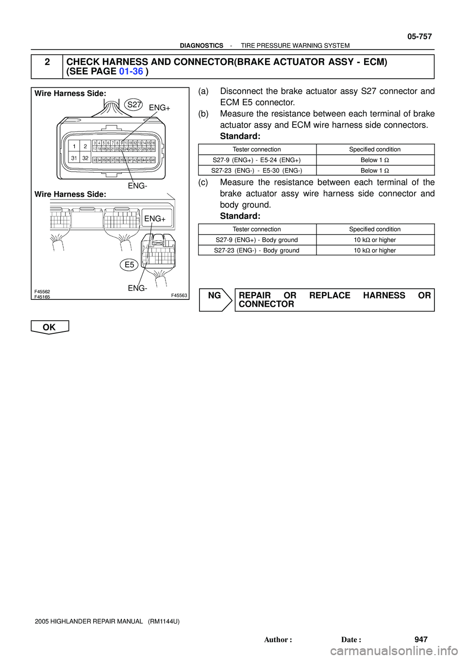
F45165F45562F45563
Wire Harness Side:
Wire Harness Side:
ENG-ENG+ENG+
ENG- S27
E5
- DIAGNOSTICSTIRE PRESSURE WARNING SYSTEM
05-757
947 Author�: Date�:
2005 HIGHLANDER REPAIR MANUAL (RM1144U)
2 CHECK HARNESS AND CONNECTOR(BRAKE ACTUATOR ASSY - ECM)
(SEE PAGE 01-36)
(a) Disconnect the brake actuator assy S27 connector and
ECM E5 connector.
(b) Measure the resistance between each terminal of brake
actuator assy and ECM wire harness side connectors.
Standard:
Tester connectionSpecified condition
S27-9 (ENG+) - E5-24 (ENG+)Below 1 W
S27-23 (ENG-) - E5-30 (ENG-)Below 1 W
(c) Measure the resistance between each terminal of the
brake actuator assy wire harness side connector and
body ground.
Standard:
Tester connectionSpecified condition
S27-9 (ENG+) - Body ground10 kW or higher
S27-23 (ENG-) - Body ground10 kW or higher
NG REPAIR OR REPLACE HARNESS OR
CONNECTOR
OK
Page 856 of 2572

A53769
ENG- ENG+
E5
E9
E1 ECM:
F45157
GND
1 V / Division
0.5 ms / Division
Normal Signal Waveform: ENG + terminal
F45158
1 V / Division
0.5 ms / Division
Normal Signal Waveform: ENG- terminal
GND
05-758
- DIAGNOSTICSTIRE PRESSURE WARNING SYSTEM
948 Author�: Date�:
2005 HIGHLANDER REPAIR MANUAL (RM1144U)
3 INSPECT ECM(ENG+, ENG- OUTPUT)
(a) Connect the brake actuator assy S27 connector and ECM
E5 connector.
(b) Remove the ECM with the connectors connected.
(c) Turn the ignition switch to the ON position.
(d) Using an oscilloscope, connect the terminals, as shown
in the chart below.
Tester Connection
E5-24 (ENG+) - E9-1 (E1)
(e) With the engine idling, check the output waveform.
OK:
Signal waveform appears as shown in the illustration.
HINT:
As the vehicle speed increases, the waveform cycle narrows.
(f) Using an oscilloscope, connect the terminals, as shown
in the chart below.
Tester Connection
E5-30 (ENG-) - E9-1 (E1)
(g) With the engine idling, check the output waveform.
OK:
Signal waveform appears as shown in the illustration.
HINT:
As the engine speed increases, the waveform cycle narrows.
NG REPLACE ECM
OK
Page 857 of 2572
 3.5
3.0
2.5
2.0
1.5
1.0
5.0
0.0
40 0
20 60 Resistance
(kW)4.0
�C
�F 104 68 140MIX
MAX
- DIAGNOSTICSTIRE PRESSURE WARNING SYSTEM
05-759
94")
I30155
Ambient Temperature Sensor:
A1
I38777
Temperature (�C) 3.5
3.0
2.5
2.0
1.5
1.0
5.0
0.0
40 0
20 60 Resistance
(kW)4.0
�C
�F 104 68 140MIX
MAX
- DIAGNOSTICSTIRE PRESSURE WARNING SYSTEM
05-759
949 Author�: Date�:
2005 HIGHLANDER REPAIR MANUAL (RM1144U)
4 INSPECT AMBIENT TEMPERATURE SENSOR
(a) Remove the ambient temperature sensor and disconnect
the A1 connector.
(b) Measure the resistance according to the value(s) in the
table below.
Standard:
Tester connectionConditionSpecified condition
A1-1 - A1-250�F (10�C)3.00 to 3.73 kW
A1-1 - A1-259�F (15�C)2.45 to 2.88 kW
A1-1 - A1-268�F (20�C)1.95 to 2.30 kW
A1-1 - A1-277�F (25�C)1.60 to 1.80 kW
A1-1 - A1-286�F (30�C)1.28 to 1.47 kW
A1-1 - A1-295�F (35�C)1.00 to 1.22 kW
A1-1 - A1-2104�F (40�C)0.80 to 1.00 kW
A1-1 - A1-211 3�F (45�C)0.65 to 0.85 kW
A1-1 - A1-2122�F (50�C)0.50 to 0.70 kW
A1-1 - A1-2131�F (55�C)0.44 to 0.60 kW
A1-1 - A1-2140�F (60�C)0.36 to 0.50 kW
HINT:
As the temperature increases, the resistance decreases (see
the chart below).
NOTICE:
Even slightly touching the sensor may change the resis-
tance value. Be sure to hold the connector of the sensor.
NG REPLACE AMBIENT TEMPERATURE SENSOR
OK
Page 858 of 2572
F46780
A1
Wire harness side:
E7
Wire harness side:
E2
TA ME6
05-760
- DIAGNOSTICSTIRE PRESSURE WARNING SYSTEM
950 Author�: Date�:
2005 HIGHLANDER REPAIR MANUAL (RM1144U)
5 CHECK HARNESS AND CONNECTOR(ECM - AMBIENT TEMPERATURE SENSOR)
(SEE PAGE 01-36)
(a) Disconnect the ECM E6 and E7 connectors.
(b) Measure the resistance according to the value(s) in the
table below.
Standard:
Tester connectionConditionSpecified condition
E6-32 (TAM) - A1-2AlwaysBelow 1 W
E7-28 (E2) - A1-1AlwaysBelow 1 W
E6-32 (TAM) - Body
groundAlways10 kW or higher
E7-28 (E2) - Body
groundAlways10 kW or higher
NG REPAIR OR REPLACE HARNESS OR
CONNECTOR
OK
REPLACE ECM (SEE PAGE 10-9 OR 10-24)
Page 961 of 2572

DTC B1214 DOOR SYSTEM COMMUNICATION BUS
MALFUNCTION (+B SHORT)
DTC B1215 DOOR SYSTEM")
05-2056
- DIAGNOSTICSMULTIPLEX COMMUNICATION SYSTEM
2246 Author�: Date�:
2005 HIGHLANDER REPAIR MANUAL (RM1144U)
DTC B1214 DOOR SYSTEM COMMUNICATION BUS
MALFUNCTION (+B SHORT)
DTC B1215 DOOR SYSTEM COMMUNICATION BUS
MALFUNCTION (GND SHORT)
CIRCUIT DESCRIPTION
B1214 and B1215 will be output when +B and body ground is short-circuited on the communication bus.
Detecting this condition will make all the BEAN communication unable and output some DTCs.
DTC No.DTC Detecting ConditionTrouble Area
B1214Communication circuit and +B battery system short
�Power window regulator master switch assy (door ECU)
�ECM
�Air conditioner amplifier assy (A/C ECU)
�Combination meter assy (meter ECU)
�Theft warning ECU assy (theft deterrent ECU)
�Sliding roof drive gear sub-assy (sliding roof ECU)
�Wire harness
�Multiplex network body ECU
B1215Communication circuit and body ground short
�Power window regulator master switch assy (door ECU)
�ECM
�Air conditioner amplifier assy (A/C ECU)
�Combination meter assy (meter ECU)
�Theft warning ECU assy (theft deterrent)
�Sliding roof drive gear sub-assy (sliding roof ECU)
�Wire harness
�Multiplex network body ECU
0523Y-04
Page 962 of 2572
B78727
ECM
Passenger
Side J/BMultiplex Network Body ECU
P5
Power Window
Regulator Master
Switch Assy
(Door ECU)
Combination
Meter Assy
Air Conditioner
Amplifier Assy MPX2
B9 10
6
O
IF3
IB25
1MPX1 Y
V8
MPX1MPX2
MPX2
7IB28
54F
4A SB
RS31
Short
Connector
A113E
G
MPX+MPX-5
12 2MPX1
1
T4
Theft Warning ECU Assy
(Theft deterrent ECU) IL2
G
A1018
29
GR
3J 3H 1Y C11 C12
21 9
MPX+
MPX- SBIL2 1 GRGR
IE16
Y
10
MPX1
MPX131 VCenter J/BS20
Sub Assy
(Sliding Roof ECU) B10
W
E6
9 2 12 BR7 GR
- DIAGNOSTICSMULTIPLEX COMMUNICATION SYSTEM
05-2057
2247 Author�: Date�:
2005 HIGHLANDER REPAIR MANUAL (RM1144U)
WIRING DIAGRAM


Combination
Meter Assy
Air Conditioner
Amplifier Assy MPX2
B9 10
6
O
IF3
IB25
1M")