Page 964 of 2572
B61053
Multiplex Network Body ECU
Communication Circuit
Communication CircuitCommunication Circuit
Communication Circuit
A ECU B ECU C ECU
- DIAGNOSTICSMULTIPLEX COMMUNICATION SYSTEM
05-2059
2249 Author�: Date�:
2005 HIGHLANDER REPAIR MANUAL (RM1144U)
2 CHECK DIAGNOSTIC TROUBLE CODE (B ECU)
(a) Check whether the output of the DTC will stop when the B ECU connector is disconnected.
NOTICE:
Disconnect the connectors in the operational sequence, and start the next operation after the con-
nector is connected.
HINT:
In this case, the B ECU represents the sliding roof drive gear sub-assy (sliding roof ECU), combination meter
assy (meter ECU), air conditioner amplifier assy (A/C ECU) or theft warning ECU assy (theft deterrent).
Standard: The disconnected B ECU or the wire harness between the A ECU and B ECU is abnor-
mal when the output of the DTC stops.
NG Go to step 4
OK
Page 1088 of 2572
B51715B79970
T1410
G K4
Unlock Warning
Switch Assy
1
2 W-B
G
KSW DD
IC W-B4L 4G 9
7J6
Junction Connector
Passenger
Side J/BTransponder Key ECU Assy 05-1998
- DIAGNOSTICSENGINE IMMOBILIZER SYSTEM
2188 Author�: Date�:
2005 HIGHLANDER REPAIR MANUAL (RM1144U)
DTC B2780 PUSH SWITCH/KEY UNLOCK WARNING
SWITCH MALFUNCTION
CIRCUIT DESCRIPTION
This DTC will be output if the transponder key ECU does not detect that the unlock warning switch is ON
even when the ignition switch is ON (under normal condition, the unlock warning switch is ON when the igni-
tion switch is ON).
DTC No.DTC Detection ConditionTrouble Area
B2780Unlock warning switch ON is not detected when ignition
switch is ON�Unlock warning switch assy
�Wire harness
�Transponder key ECU assy
WIRING DIAGRAM
05A2A-06
Page 1089 of 2572

INSPECTION PROCEDURE
HINT:
Start the inspection from step 1")
B51581
21
3 4Pushed Not pushed
- DIAGNOSTICSENGINE IMMOBILIZER SYSTEM
05-1999
2189 Author�: Date�:
2005 HIGHLANDER REPAIR MANUAL (RM1144U)
INSPECTION PROCEDURE
HINT:
Start the inspection from step 1 when using the hand-held tester and start from step 2 when not using the
hand-held tester.
1 READ VALUE OF HAND-HELD TESTER
(TRANSPONDER KEY ECU (SWITCH CONDITION))
(a) Connect the hand-held tester to the DLC3.
(b) Turn the ignition switch ON with the key that cannot start the engine.
(c) On the hand-held tester, select the following menu item: DIAGNOSIS/ENHANCED OBD II/DATA
LIST/IMMOBILISER/KEY SW. Read the values.
OK: ºONº (Key is in ignition key cylinder) appears on the screen.
ItemMeasurement Item/
Display (Range)Normal ConditionDiagnostic Note
KEY SWUnlock warning switch signal
/ON or OFFON: Key is in ignition key cylinder
OFF: No key is in ignition key cyl-
inder
-
NG Go to step 2
OK
REPLACE TRANSPONDER KEY ECU ASSY
2 INSPECT UNLOCK WARNING SWITCH ASSY
(a) Remove the unlock warning switch.
(b) Measure the resistance of the unlock warning switch.
Standard:
Tester ConnectionSwitch PositionSpecified Condition
1 - 2PushedBelow 1 W
1 - 2Not pushed10 kW or higher
NG REPLACE UNLOCK WARNING SWITCH ASSY
OK
Page 1090 of 2572
B63404
B65748B78556
T14
Transponder Key ECU Assy
K4
Unlock Warning Switch Assy Wire Harness Side
KSW
05-2000
- DIAGNOSTICSENGINE IMMOBILIZER SYSTEM
2190 Author�: Date�:
2005 HIGHLANDER REPAIR MANUAL (RM1144U)
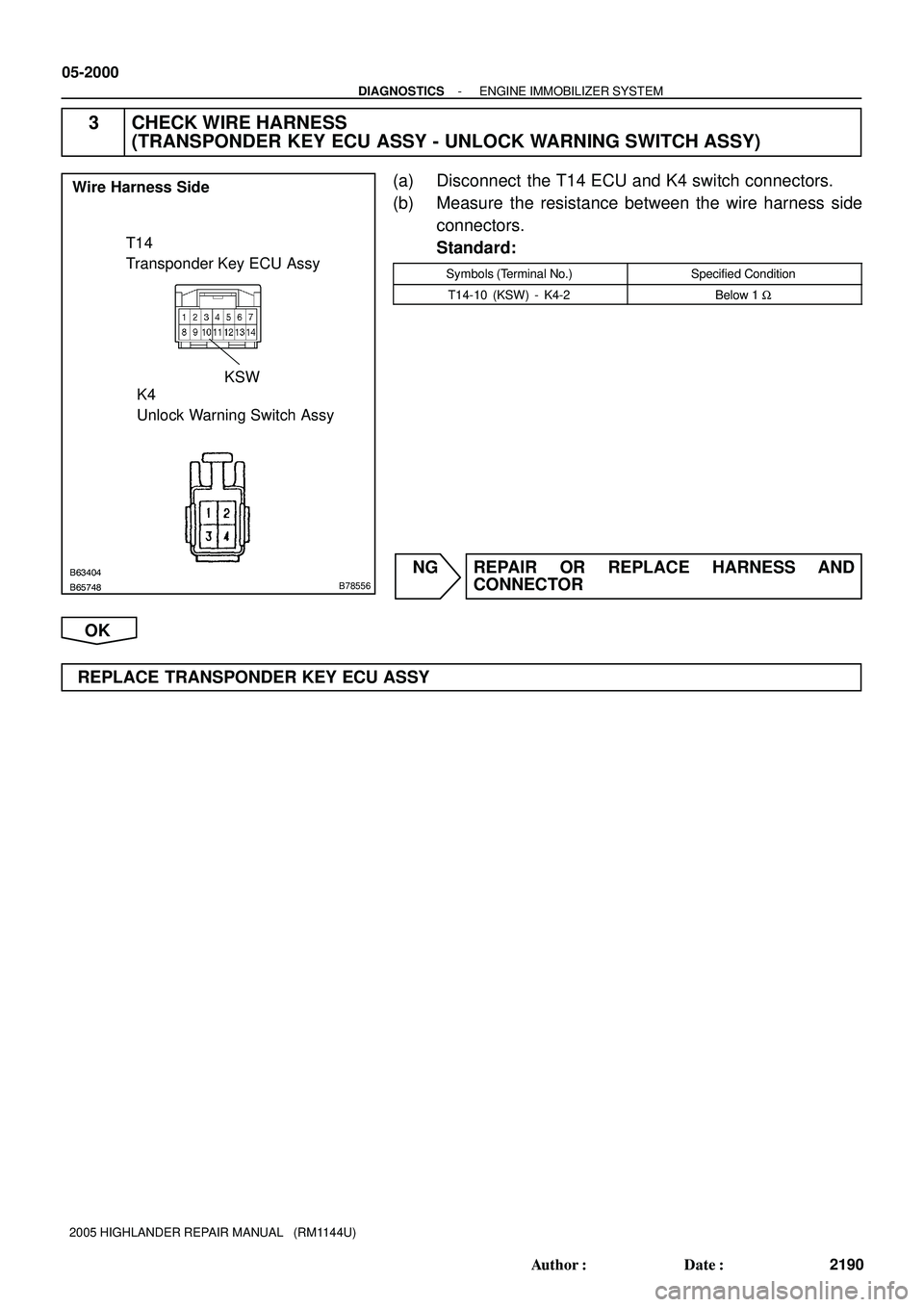
3 CHECK WIRE HARNESS
(TRANSPONDER KEY ECU ASSY - UNLOCK WARNING SWITCH ASSY)
(a) Disconnect the T14 ECU and K4 switch connectors.
(b) Measure the resistance between the wire harness side
connectors.
Standard:
Symbols (Terminal No.)Specified Condition
T14-10 (KSW) - K4-2Below 1 W
NG REPAIR OR REPLACE HARNESS AND
CONNECTOR
OK
REPLACE TRANSPONDER KEY ECU ASSY
Page 1252 of 2572
- DIAGNOSTICSMULTIPLEX COMMUNICATION SYSTEM
05-2075
2265 Author�: Date�:
2005 HIGHLANDER REPAIR MANUAL (RM1144U)
DTC B1269/69 THEFT DETERRENT ECU COMMUNICATION
STOP
CIRCUIT DESCRIPTION
B1269/69 will be output when the communication between the theft warning ECU assy (theft deterrent ECU)
and multiplex network body ECU stops for more than 10 seconds.
DTC No.DTC Detecting ConditionTrouble Area
B1269/69No communication from theft deterrent ECU for more than 10 seconds�Theft warning ECU assy (theft deterrent ECU)
�Wire harness
05241-06
Page 1253 of 2572
H45692
T4
Theft Warning ECU Assy
(Theft Deterrent ECU)
A10
Air Conditioner
Amplifier Assy
(A/C ECU) F7
FL Block AssyEngine Room J/B
Combination
Meter 1 41D9
MPX1
21 1G10
BR
2A
2I SECURITYW-L3 IC3
BatteryJ17
J/C
1ECU-B
MPX- 3H V IF1
35
Y31
Center
J/B
3E 3J L
+B2
+B1
2 O
IL1112
W 4
L
P P
IC3 5
52A
D.C.C.
W
FL Main WMPX-C11
G53D
3F 11213
9W-B
IB 29
W-B EEE Instrument
Panel J/B 05-2076
- DIAGNOSTICSMULTIPLEX COMMUNICATION SYSTEM
2266 Author�: Date�:
2005 HIGHLANDER REPAIR MANUAL (RM1144U)
WIRING DIAGRAM
Page 1254 of 2572
H45691
Theft Warning ECU Assy
(Theft Deterrent ECU)
Air Conditioner
Amplifier Assy
(A/C ECU)
Combination MeterA10
C11 T4
- DIAGNOSTICSMULTIPLEX COMMUNICATION SYSTEM
05-2077
2267 Author�: Date�:
2005 HIGHLANDER REPAIR MANUAL (RM1144U)
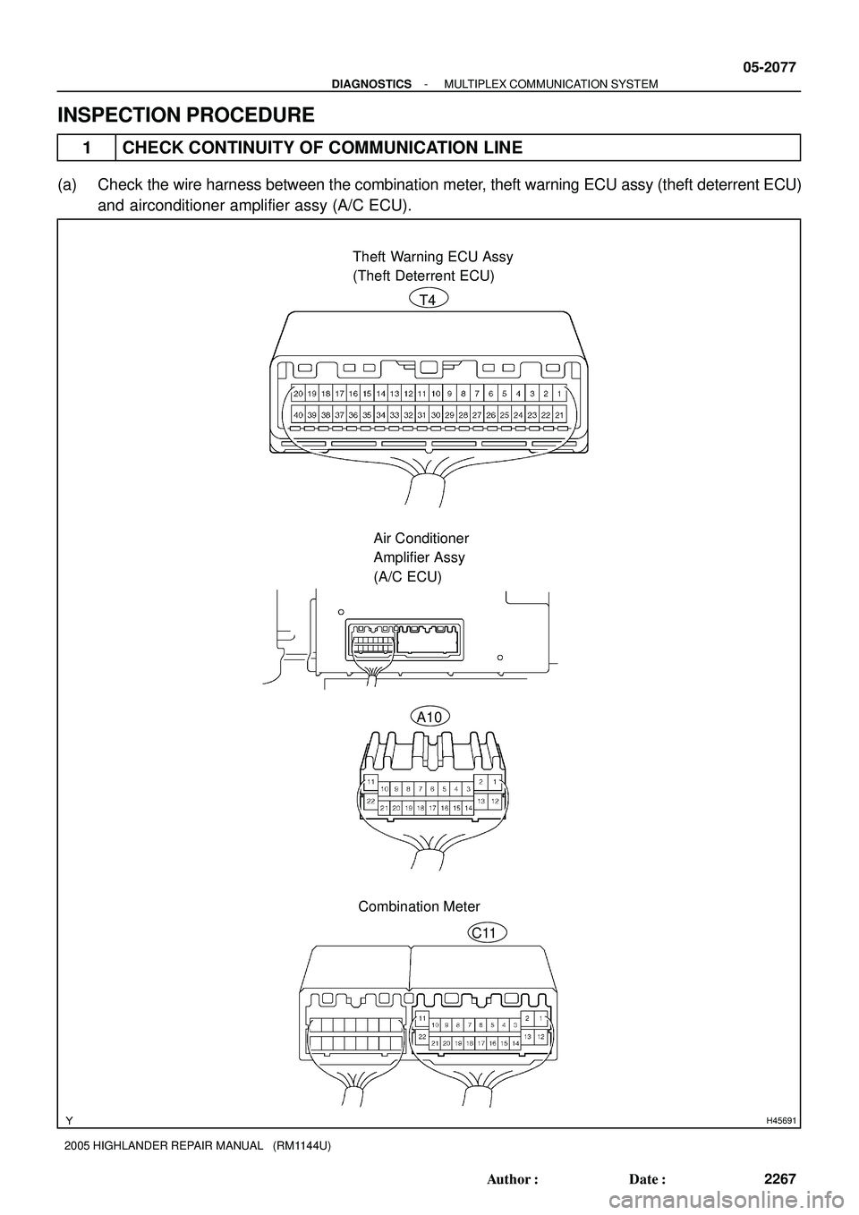
INSPECTION PROCEDURE
1 CHECK CONTINUITY OF COMMUNICATION LINE
(a) Check the wire harness between the combination meter, theft warning ECU assy (theft deterrent ECU)
and airconditioner amplifier assy (A/C ECU).
Page 1255 of 2572

(1) Disconnect the connectors of the theft warning ECU, master switch and")
B50657
4T4
05-2078
- DIAGNOSTICSMULTIPLEX COMMUNICATION SYSTEM
2268 Author�: Date�:
2005 HIGHLANDER REPAIR MANUAL (RM1144U)
(1) Disconnect the connectors of the theft warning ECU, master switch and air conditioner amplifier.
(2) Check the continuity between terminal T4-31 (MPX1) of the theft warning ECU vehicle's side
connector and terminal C11-21 (MPX-) of the master switch vehicle's side connector.
(3) Check the continuity between terminal T4-31 (MPX1) of the theft warning ECU vehicle's side
connector and terminal A10-9 (MPX-) of the air conditioner amplifier vehicle's side connector.
Standard: Continuity
NG REPAIR OR REPLACE HARNESS AND
CONNECTOR
OK
2 CHECK THEFT WARNING ECU ASSY
(a) Inspect the theft warning ECU assy (theft deterrent ECU) (power source input).
(1) Disconnect the theft warning ECU connector.
(2) Check the voltage between terminal T4-2 (+B1) and T4-8 (+B2) of the theft warning ECU and
the body ground.
Standard: 10 - 14 V
NG REPAIR OR REPLACE FUSE OR WIRE
HARNESS AND CONNECTOR
OK


A10
Air Conditioner
Amplifier Assy
(A/C ECU) F7
FL Block AssyEngine Room J/B
Combination
Meter 1 41D9
MPX1
21 1G10
BR
2A
2I SECURITYW-L3 IC3
B")