Page 2048 of 2572
05EYW-02
F46771
Skid
Control
ECUTire Pressure Warning
Reset Switch
ECM
Right Front Speed Sensor
Stop Lamp Switch Assy
Combination Meter Assy
(Tire Pressure Warning Lamp)Ambient Temperature
Sensor
Left Front Speed Sensor
Right Rear Speed Sensor
Left Rear Speed Sensor 05-732
- DIAGNOSTICSTIRE PRESSURE WARNING SYSTEM
922 Author�: Date�:
2005 HIGHLANDER REPAIR MANUAL (RM1144U)
SYSTEM DIAGRAM
Page 2052 of 2572
05-1522
- DIAGNOSTICSSUPPLEMENTAL RESTRAINT SYSTEM
1712 Author�: Date�:
2005 HIGHLANDER REPAIR MANUAL (RM1144U)
TC TERMINAL CIRCUIT
CIRCUIT DESCRIPTION
The DTCs output mode is set by connecting terminals TC and CG of the DLC3.
The DTCs are displayed by blinking the SRS warning light.
HINT:
�Make sure that DTC B1281 has not been output. If DTC B1281 has been output, refer to the multiplex
communication system.
�When each warning light stays blinking, a ground short in the wiring of terminal TC of the DLC3 or an
internal ground short in each ECU is suspected.
�The DTC output mode signal is transmitted through BEAN to each ECU including the airbag sensor
assy center, except for the skid control ECU with actuator. Thus when all systems except the ABS sys-
tem do not enter DTC output mode, it can be suspected that there is an ECM malfunction.
0526A-05
Page 2056 of 2572
B80404
2A1G IC3
BATTERY FL MAIN W W
F7
FUSIBLE
LINK BLOCKEngine Room J/B
SECURITY ECU-B
D.C.C
3
12I
1 W - L5
BR
109 INSTRUMENT PANEL J/B ASSY
2A 451DP
EE J17
J/C
P11
IL1O2 Theft Warning ECU Assy T4
+B1
+B2
SH- 13
IF12
W 4
IC3L L
LG
IF3 17
B
2 IC3
T1
Theft Deterrent
Horn B - O
1
05-2028
- DIAGNOSTICSTHEFT DETERRENT SYSTEM
2218 Author�: Date�:
2005 HIGHLANDER REPAIR MANUAL (RM1144U)
THEFT DETERRENT HORN CIRCUIT
CIRCUIT DESCRIPTION
When the theft deterrent system is operating, the relay in the ECU turns on and off in a cycle of approximately
0.2 seconds, causing the theft warning horn to blow (see the wiring diagram below).
WIRING DIAGRAM
INSPECTION PROCEDURE
1 CHECK THEFT WARNING ECU ASSY (SECURITY)
(a) Remove the SECURITY fuse from the engine room J/B.
(b) Measure the resistance.
Standard: Below 1 W
NG REPAIR OR REPLACE HARNESS AND
CONNECTOR
OK
05ITM-04
Page 2057 of 2572
B63408
Wire Harness Side
T4
Theft Warning ECU Assy
B51580
1
B51580
1
B64984
- DIAGNOSTICSTHEFT DETERRENT SYSTEM
05-2029
2219 Author�: Date�:
2005 HIGHLANDER REPAIR MANUAL (RM1144U)
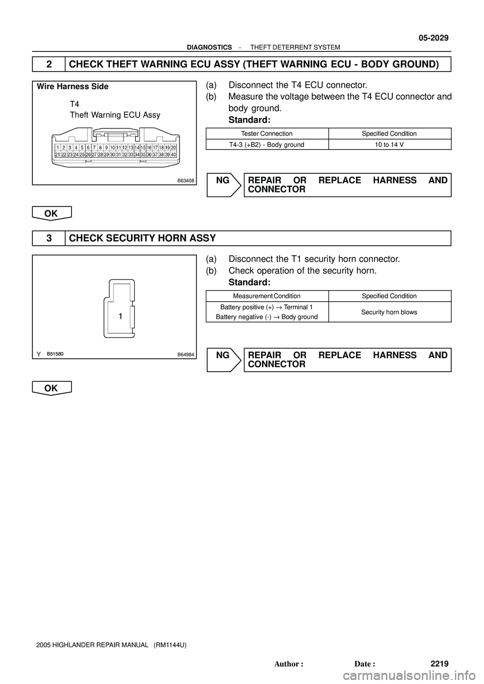
2 CHECK THEFT WARNING ECU ASSY (THEFT WARNING ECU - BODY GROUND)
(a) Disconnect the T4 ECU connector.
(b) Measure the voltage between the T4 ECU connector and
body ground.
Standard:
Tester ConnectionSpecified Condition
T4-3 (+B2) - Body ground10 to 14 V
NG REPAIR OR REPLACE HARNESS AND
CONNECTOR
OK
3 CHECK SECURITY HORN ASSY
(a) Disconnect the T1 security horn connector.
(b) Check operation of the security horn.
Standard:
Measurement ConditionSpecified Condition
Battery positive (+) " Terminal 1
Battery negative (-) " Body groundSecurity horn blows
NG REPAIR OR REPLACE HARNESS AND
CONNECTOR
OK
Page 2058 of 2572
B63408
B58961
1
B63408
B58961
1
B64978
Wire Harness Side
T1
Security Horn Assy T4
Theft Warning ECU Assy
05-2030
- DIAGNOSTICSTHEFT DETERRENT SYSTEM
2220 Author�: Date�:
2005 HIGHLANDER REPAIR MANUAL (RM1144U)
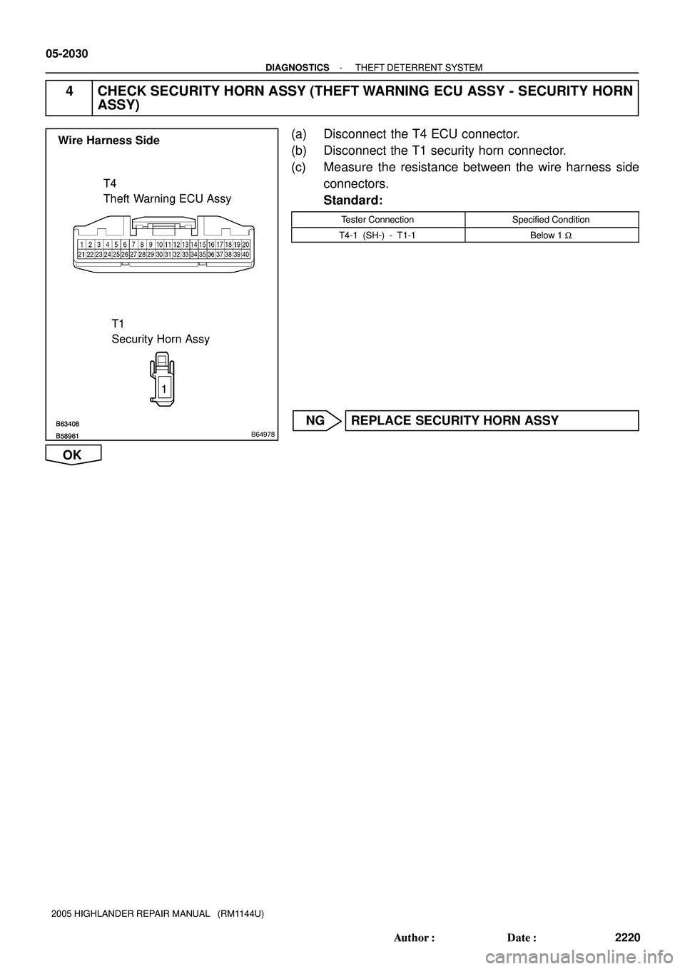
4 CHECK SECURITY HORN ASSY (THEFT WARNING ECU ASSY - SECURITY HORN
ASSY)
(a) Disconnect the T4 ECU connector.
(b) Disconnect the T1 security horn connector.
(c) Measure the resistance between the wire harness side
connectors.
Standard:
Tester ConnectionSpecified Condition
T4-1 (SH-) - T1-1Below 1 W
NG REPLACE SECURITY HORN ASSY
OK
Page 2059 of 2572
F46776
S27
Skid Control ECU
With Actuator Passenger Side J/B S15
Stop Light SW
Instrument Panel J/B
BatterySTP
27 IC4 4A11
4L
STOP
F7
FL Block
FL MAIN
EAJ4
J/CW-B
GND1 G-Y B 3
B
1 2
Y
1E1
1A1
B
B ALT32
A
EB W-BW-B W
1222 05-748
- DIAGNOSTICSTIRE PRESSURE WARNING SYSTEM
938 Author�: Date�:
2005 HIGHLANDER REPAIR MANUAL (RM1144U)
STOP LAMP SWITCH CIRCUIT
CIRCUIT DESCRIPTION
When the stop lamp switch is ON (brake pedal depressed), the skid control ECU suspends the tire pressure
warning system.
WIRING DIAGRAM
05IOZ-02
Page 2060 of 2572
F45562
Wire Harness Side:
S27STP
GND1
- DIAGNOSTICSTIRE PRESSURE WARNING SYSTEM
05-749
939 Author�: Date�:
2005 HIGHLANDER REPAIR MANUAL (RM1144U)
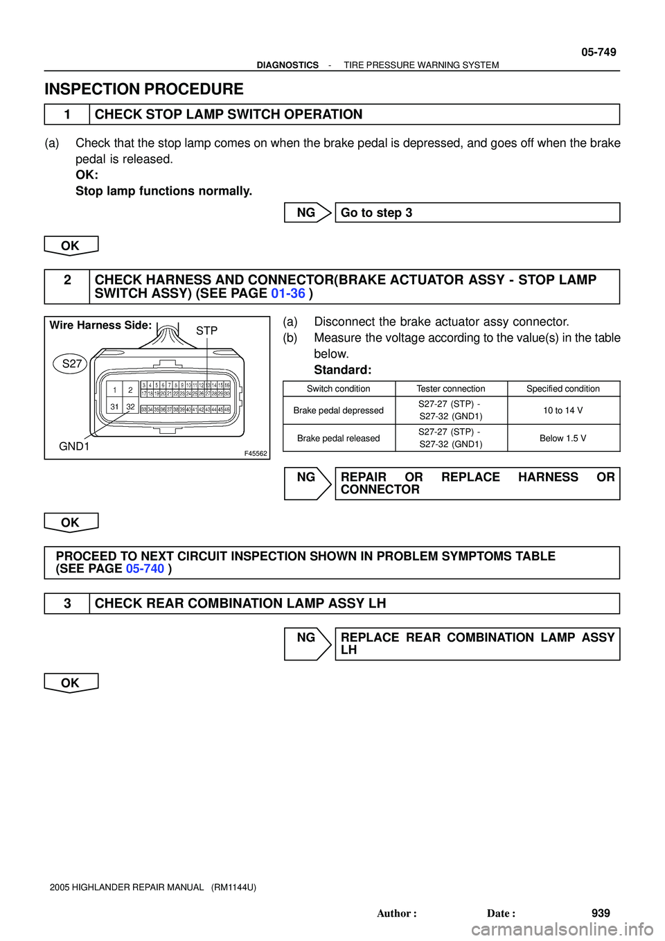
INSPECTION PROCEDURE
1 CHECK STOP LAMP SWITCH OPERATION
(a) Check that the stop lamp comes on when the brake pedal is depressed, and goes off when the brake
pedal is released.
OK:
Stop lamp functions normally.
NG Go to step 3
OK
2 CHECK HARNESS AND CONNECTOR(BRAKE ACTUATOR ASSY - STOP LAMP
SWITCH ASSY) (SEE PAGE 01-36)
(a) Disconnect the brake actuator assy connector.
(b) Measure the voltage according to the value(s) in the table
below.
Standard:
Switch conditionTester connectionSpecified condition
Brake pedal depressedS27-27 (STP) -
S27-32 (GND1)10 to 14 V
Brake pedal releasedS27-27 (STP) -
S27-32 (GND1)Below 1.5 V
NG REPAIR OR REPLACE HARNESS OR
CONNECTOR
OK
PROCEED TO NEXT CIRCUIT INSPECTION SHOWN IN PROBLEM SYMPTOMS TABLE
(SEE PAGE 05-740)
3 CHECK REAR COMBINATION LAMP ASSY LH
NG REPLACE REAR COMBINATION LAMP ASSY
LH
OK
Page 2061 of 2572

4")
F45894
Stop Lamp Switch Assy:
1 2
Pushed In Free
F45562
Wire Harness Side:
S27STP
GND1
05-750
- DIAGNOSTICSTIRE PRESSURE WARNING SYSTEM
940 Author�: Date�:
2005 HIGHLANDER REPAIR MANUAL (RM1144U)
4 INSPECT STOP LAMP SWITCH ASSY
(a) Disconnect the stop lamp switch assy S15 connector.
(b) Measure the resistance according to the value(s) in the
table below.
Standard:
Switch conditionTester connectionSpecified condition
Switch pin free1 - 2Below 1 W
Switch pin pushed in1 - 210 kW or higher
NG REPLACE STOP LAMP SWITCH ASSY
OK
5 CHECK HARNESS AND CONNECTOR(BRAKE ACTUATOR ASSY - STOP LAMP
SWITCH ASSY) (SEE PAGE 01-36)
(a) Connect the stop lamp switch assy S15 connector.
(b) Disconnect the brake actuator assy connector.
(c) Measure the voltage according to the value(s) in the table
below.
Standard:
Switch conditionTester connectionSpecified condition
Brake pedal depressedS27-27 (STP) -
S27-32 (GND1)10 to 14 V
Brake pedal releasedS27-27 (STP) -
S27-32 (GND1)Below 1.5 V
NG REPAIR OR REPLACE HARNESS OR
CONNECTOR
OK
PROCEED TO NEXT CIRCUIT INSPECTION SHOWN IN PROBLEM SYMPTOMS TABLE
(SEE PAGE 05-740)
Ambient Temperature
Sensor
Le")