Page 2241 of 2572
Trouble AreaSRS
� Steering wheel pad (squib)
�")
�
Detection Item
Indicates the system or details of the
problem.Trouble Area
Indicates the suspect areas of
the problem.
Detection Item DTC No.
(See page)Trouble AreaSRS
� Steering wheel pad (squib)
� Spiral cable
� Airbag sensor assembly
� Wire harness
B0103/12
(05-132) B0102/11
(05-128)
DIAGNOSTIC TROUBLE CODE CHART
If a malfunction code is displayed during the DTC check, check the circuit for that code listed in the table
below (Proceed to the page given for that circuit).
� Short in D squib circuit
� Open in D squib circuit
B0101/14
(05-124)
� Short in D squib circuit (to ground)
� Short in D squib circuit (to B+)
Warning Light
ON
ON
ON
ON � Steering wheel pad (squib)
� Spiral cable
� Airbag sensor assembly
� Wire harness
� Steering wheel pad (squib)
� Spiral cable
� Airbag sensor assembly
� Wire harness
� Steering wheel pad (squib)
� Spiral cable
� Airbag sensor assembly
� Wire harness
B0105/53
(05-136)ON
� Airbag sensor assembly
� Wire harness B0106/54� Open in P squib circuit
� Airbag sensor assembly
� Wire harness � Short in P squib circuit (to Ground)ON
ON B0100/13
(05-1 19)
� Short in P squib circuit� Front passenger airbag assembly (squib)
� Airbag sensor assembly
� Wire harness
� Front passenger airbag assembly (squib)
� Front passenger airbag assembly (squib)
Page or Instructions
Indicates the page where the inspection proce-
dures for each circuit is to be found, or gives
instructions for checking and repairs. �DTC No.
Indicates the diagnostic trouble code.
��
- INTRODUCTIONHOW TO TROUBLESHOOT ECU CONTROLLED
SYSTEMS01-33
33 Author�: Date�:
2005 HIGHLANDER REPAIR MANUAL (RM1144U)
DIAGNOSTIC TROUBLE CODE CHART
Use Diagnostic Trouble Codes (DTCs) (from the DTC checks) in the table below to determine the trouble
area and proper inspection procedure. The Supplemental Restraint System (SRS) diagnostic trouble code
chart is shown below as an example.
Page 2242 of 2572

PROBLEM SYMPTOMS TABLE
The suspected circuits or parts for each problem sympt")
01-34- INTRODUCTIONHOW TO TROUBLESHOOT ECU CONTROLLED
SYSTEMS
34 Author�: Date�:
2005 HIGHLANDER REPAIR MANUAL (RM1144U)
PROBLEM SYMPTOMS TABLE
The suspected circuits or parts for each problem symptom are shown in the table below. Use this table to
troubleshoot when, during a DTC check, a ºNormalº code is displayed but the problem is still occurring. Num-
bers in the table show the inspection order in which the circuits or parts should be checked.
HINT:
In some cases, the problem is not detected by the diagnostic system even though a problem symptom is
present. It is possible that the problem is occurring outside the detection range of the diagnostic system, or
that the problem is occurring in a completely different system.
Symptom
Suspected AreaSee Page
PROBLEM SYMPTOMS TABLE
05-1277
Problem SymptomPage
Indicates the page where the flow chart for each circuit
is located.
Circuit Inspection, Inspection Order
Indicates the circuit which needs to be checked for each problem
symptom. Check in the order indicated by the numbers.
Circuit or Part Name
Indicates the circuit or part which needs to be checked.
Inspect the ºFuseº and ºRelayº before confirming the suspected area in the charts below (See page 68-1).
1. SRS warning light circuit (multi-display assy)
1. Steering pad switch circuit
05-1267
��
�
�
HINT:
1. Power source circuit (multi-display assy)
Black screen
2. Multi-display 67-7
Screen cannot be dimmer in night time
2. Multi-display assy 67-7
A navigation system cannot be operated2. AVC-LAN circuit (radio receiver assy-multi-
display assy)
3. Radio receiver assy
4. Multi-display assy05-1 183
05-1303
67-5
67-7
Page 2244 of 2572

ii
Important information about this manual
For safety reasons, this manual indicates
items requiring particular attention with the
following marks.
CAUTION
This is a warning against anything
which may cause injury to people if the
warning is ignored. You are informed
about what you must or must not do in
order to reduce the risk of injury to
yourself and others.
NOTICE
This is a warning against anything
which may cause damage to the ve-
hicle or its equipment if the warning is
ignored. You are informed about what
you must or must not do in order to
avoid or reduce the risk of damage to
your vehicle and its equipment.
INFORMATION
This provides additional information.
Initial screen
When you start the engine or turn the ignition
switch to the ACCº position, the initial
screen appears and the system begins
operating.
CAUTION
When the vehicle is stopped with the
engine running, always apply the park-
ing brake for safety.
After a few seconds, the CAUTIONº screen
appears.
Touch either Englishº or
Fran†aisº to select a language. Read
and follow the instructions.
When you touch the
I Agreeº switch
on the screen, the map screen appears.
You can access this screen when you push
the
INFOº button and touch the Lan-
guageº
switch. Then you can select a lan-
guage.
Page 2253 of 2572
- DIAGNOSTICSCOMBINATION METER
05-1897
2087 Author�: Date�:
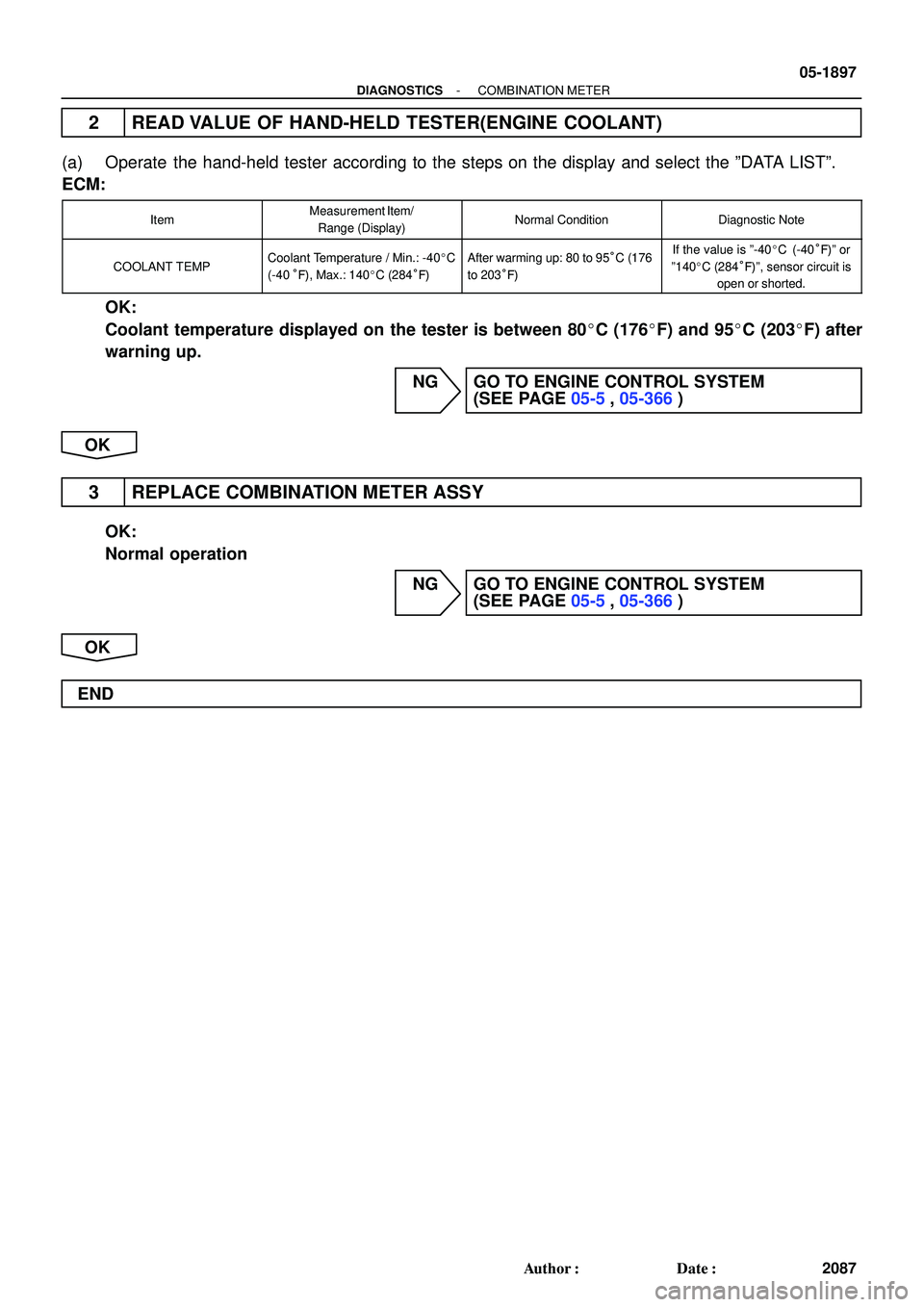
2 READ VALUE OF HAND-HELD TESTER(ENGINE COOLANT)
(a) Operate the hand-held tester according to the steps on the display and select the ºDATA LISTº.
ECM:
ItemMeasurement Item/
Range (Display)Normal ConditionDiagnostic Note
COOLANT TEMPCoolant Temperature / Min.: -40�C
(-40°F), Max.: 140�C (284°F)After warming up: 80 to 95°C (176
to 203°F)If the value is º-40�C (-40°F)º or
º140�C (284°F)º, sensor circuit is
open or shorted.
OK:
Coolant temperature displayed on the tester is between 80�C (176�F) and 95�C (203�F) after
warning up.
NG GO TO ENGINE CONTROL SYSTEM
(SEE PAGE 05-5, 05-366)
OK
3 REPLACE COMBINATION METER ASSY
OK:
Normal operation
NG GO TO ENGINE CONTROL SYSTEM
(SEE PAGE 05-5, 05-366)
OK
END
Page 2287 of 2572

M OVERALL ELECTRICAL WIRING DIAGRAM
34
2 1
(
Cont. next page)
15 HIGHLANDER
A
B
D V
P
V
P
4E 1
P
555
55
ABS MTR Relay
LG
B- R
4C 2
B- OB- OLG G- RB
45 15 14 31219 5 6 20
B")
2005 HIGHLANDER (EWD592U)
M OVERALL ELECTRICAL WIRING DIAGRAM
34
2 1
(
Cont. next page)
15 HIGHLANDER
A
B
D V
P
V
P
4E 1
P
555
55
ABS MTR Relay
LG
B- R
4C 2
B- OB- OLG G- RB
45 15 14 31219 5 6 20
B M RL+ RL- RR+ RR-
+BS MRF MR R+
2 1
2 1 2 1
2 1
7 IC2 16 IC2 6 IC2 15 IC2
RV GRP
Y- GG
W- LY BR
Power SourceV S C a nd Tire P ressu re W a rn in g System
O18FL+ FL-
4
P R- Y
3FR+ FR-
17
LG
ABS CUT Relay GR
4H 2 4C 11C L
L
1 2GBR-W
B- R
46
IG1 BZ302 IA1 12 IA1 1 IO2 2 IO2
Y OL R
30A AM2
FL MAIN
3. 0W
50A ABS2
W
2ACC
IG1
IG2
ST 2 AM1 4
6 7AM2
1A 11C 6
30A ABS1
140A ALT
2B WY
40A AM11 2
1
1IC1
L- YB10 89 W
Bat tery 2I 12A 4GRG
7. 5A ECU- B
3W D. C. C
BR10A ECU- IG
1C 7
1D 10
10A IGN
1C 1
1G 6 GR
G
4M 4WE EP
84M
G
20 IC4 10 IC4
GRO
4J 4
Y
55
W- L
G- R
5
25 13
2 51
3 B B- O 10 1G1D 9
W- L PB- R
ST 1
10A HEATER
1K 13E BB
5IC3
W
I15
F 7S2 7
A2 5
A2 4
V 8
J 6A 5
A 4
ABS Speed Sensor Front LH ABS Speed Sensor Front RH
ABS Speed Sens or
Re ar L H ABS Speed Sens or
Re ar RH
Fusible Link Bloc kI gnit ion SW
J unc tion
Connec tor
Sk i d Con t ro l ECU wi t h Ac t u at o rVSC Warning Buzzer
Page 2289 of 2572
2005 HIGHLANDER (EWD592U)
M OVERALL ELECTRICAL WIRING DIAGRAM
1112
10 9
15 HIGHLANDER (
Cont' d)
L
W G
W
B
W
Y
W Data Link Connect or 3
<2- 18><3- 14>
L P
W- B P
13
2910CA NL CA NH IG1 BAT
ESS
SB B
CP
P
GVA 11 B 6 B 11 A 17 L V
B W
O VW-B32 5
1 GNDCA NH CA NL IG
BFNear the Rear
Side Mark er Light RH
W- B
13
7B
SB
BR
W
L
P WB GR SB
IBRBR
Speedometer
VSC Brake
A
3K 23B 12
Right Instrument
Panel Brace A
H
I
VSC and Tire Pressure W arning System
D
F
J
K
M u ltip le x C o m m u n ic a tio n S y s te m (
CAN)
3IO2 12IO2 13IO2
G W
E E
21 10 22 11 20 9
19 8 9IL1 P
ABSBR
16 IF3 6 IF2 6 IF3 18 IF3
BR
SB
SB
15 IF3
EB Right Front
Fender Apr on
VR R-BA B
E7
3C 4
3A
1A
P
B 10
1IC4
A A
BBRight Center
Pillar
W- B
J19
A
W- B
Slip
TRAC OFF
Tire Air
Pressure (
2WD)(
2WD)
LW- B
W- B
C1 1(
A)
, C12(
B)
B 4
J16 Y 1
J19J17
J 4Brake Warning SW
Combination Meter
Junc tion
Connec torJunction Connector
Junct ion
Connect or
Junction
Connector
Steering Sens or
Yaw Rate Sensor
S14
2 1
Page 2298 of 2572

M
5
678
18 HIGHLANDER (
Cont d)
W ireless D oor
Lock Control
D C BG
L
W- B1IN2 8IN2
V
13 B
SBSB V
GR4 3
LULPKUL
8B
VPKL
2IN211 B
BRBR BR6
LSSR LSWP
5IN1
LW1
L4IN1
WR2
UL C")
2005 HIGHLANDER (EWD592U)
M
5
678
18 HIGHLANDER (
Cont' d)
W ireless D oor
Lock Control
D C BG
L
W- B1IN2 8IN2
V
13 B
SBSB V
GR4 3
LULPKUL
8B
VPKL
2IN211 B
BRBR BR6
LSSR LSWP
5IN1
LW1
L4IN1
WR2
UL C C
C
W
5E6DWACT-
A A
AA
G
C C
CC
V
BALeft Center Pillar 11 BB1
W- B W- B
6BB1 13BB1
B GB-W
GR
3 17BB1
VL-B4
2 IA110
V
BBRight Center Pillar 13 BC1
W- B W- B
11 BC1 6 BC1
V SB B- W
L- B
1 27BC1
BR GR4
3A A
AA
B 17 DBLSWA
17 BH1 8 BH1 15 BH1
BELeft Side of Back Door
W- B
3BG2 1BG2
V GG
R
1 28BG3
BV4
32BKSW
B
V GB
4H 11
4L 7
W- BIC Right Cowl Side
Panel7DW- BGND1W- B
W
G
A17 C
YPRG
16 C
GRRDA AR
BFRight Side of
Rear Cross Member
W- B R
BR SB B
W- B325
1 15 IO2 10 IO214 IO2
Door Lock Control
E PRG RDA +B
Key Reminder and
Seat Belt Warning System
<26- 2>19 AHA Z
L15 CBZR
W
14 IK3
L- Y2 1
IK3 3W- B W- B4M 3
LSSR L UL
EUL L LSSR
EACT- ACT+ S
E 3IA1
B
BCLeft Side of
Re ar Cr oss
MemberW- BD D
B
Tur n Signal Flasher
<8- 3>
A A
AJ19
W- B D13D1 4
W 5
W 6 J12 B 9(
A)
, B10(
B)
, B11(
C)
, B12(
D)
J10
J 5 J10
J14B15 D15 Body ECU
Bac k Door Lock Motor
Bac k Door Unlock Detection SW
Door Key Lock and Unloc k SW Front RH
Door Lock Motor Front RH
Door Unlock Det ect ion SW Front RHDoor Loc k Motor Rear LH
Door Unlock Det ection SW
Re ar L HDoor Lock Motor Rear RH
Door Unlock Detection
S W Re ar RH Junct ion
Connect orJunc tion
Connec tor
J unc tion
Connec torJunct ion
Connect or
Junction
Connector
J unc tion
Connec tor
Junction
Connector
Wireless Door Lock
Buzzer
Wireless Door Lock
ECU
J18
Bu zz er
Page 2299 of 2572

M OVERALL ELECTRICAL WIRING DIAGRAM
1
234
19 HIGHLANDER
Power SourceT he ft D ete rren t S y s tem
7. 5A ECU- B
15A SECURI TY
2A 4 2A 5
2I 12ACC
IG1 AM1 4
40A
AM1
1A 11C 6")
2005 HIGHLANDER (EWD592U)
M OVERALL ELECTRICAL WIRING DIAGRAM
1
234
19 HIGHLANDER
Power SourceT he ft D ete rren t S y s tem
7. 5A ECU- B
15A SECURI TY
2A 4 2A 5
2I 12ACC
IG1 AM1 4
40A
AM1
1A 11C 6
32
110A
ECU- I G 1C 7
1K 9
3A 1
3E 5
3J 11
3F 13
IBRight Ins tr ument
Panel Br ac e17 IL2
14 IA28IL2
4IA2
9BG3 4BG2
SB BR
Y LG
V B
BRY23 15 33 31
Multiplex Communication
Sy st em (
BEAN Bus)
<20- 4>A
BE Left Side of
Ba ck Do or1 23110
114IC3
2IF1 5IC3
1G 10
1D 9
11 IL1 18 IL2
3C 8
3B 2
1 26IL2
15 IK317 IF3
2IC3
1 A
EG Under the Left
He ad li g ht G
D. C. C
1 2
WW
Batt ery
W- B W- B
3 212L
BRWL
OP G
P
R
W- BB
W- B LG B B- O
WG G-BW-B
2 1
140A ALT
IG
I OUT MPX1 L UL DSWH
34 +B2 +B1 KSW
SH- E
1 29
W- B L
W- LRG
O
FL MAIN
3. 0W
Unlock Warning SW
<26- 2>
53D
3F 1125
W- B O
O
IND S+B
GND IOUT
WOp t i on
Connec tor 1
<20- 4> Op t i on
Connec tor 1
<20- 4>
BLG
(
*1)(
*1)* 1 : w/ o Theft Deter rent Sys tem
E E
P
YW- L
B
ST1
11 3K
Tr ans ponder Key Comput er
<4- 4>
R F 7I15
T 4
T 5
O 4E 3T 1
J 1 B14
J14Back Door Key Lock
and Unloc k SWEngine Hood
Courtesy SW
Fusible Link
BlockIgnition SW
J unc tion
Connec tor Junc tion
Connec tor
Option Connector 2Theft Deterrent
Ho r n
Theft Deterrent ECU
Theft Deterrent
Indicator Light
Junction
Connector J17

M OVERALL ELECTRICAL WIRING DIAGRAM
1112
10 9
15 HIGHLANDER (
Cont d)
L
W G
W
B
W
Y
W Data Link Connect or 3
<2- 18><3- 14>
L P
W- B P
13
2910CA NL CA NH IG1 BAT
ESS
SB")