Page 2062 of 2572
- DIAGNOSTICSTIRE PRESSURE WARNING SYSTEM
05-751
941 Author�: Date�:
2005 HIGHLANDER REPAIR MANUAL (RM1144U)
ABS SYSTEM MALFUNCTION
CIRCUIT DESCRIPTION
The skid control ECU outputs DTCs when a speed sensor malfunction occurs or there is an open in the stop
lamp switch assy circuit of the ABS system. If ABS system has a malfunction, tire pressure warning system
will not function.
INSPECTION PROCEDURE
1 CHECK DIAGNOSTIC TROUBLE CODE OUTPUT
(a) Check that the normal code is output by ABS system (see page 05-765).
OK:
DTC is not output.
NG REPAIR CIRCUIT INDICATED BY OUTPUT
CODE
OK
PROCEED TO NEXT CIRCUIT INSPECTION SHOWN IN PROBLEM SYMPTOMS TABLE
(SEE PAGE 05-740)
05EZ4-02
Page 2063 of 2572
F46777
S27
Skid Control ECU
With Actuator
Passenger Side J/B
INIT
41
GND1 J4
J/C
EB P22
Tire Pressure Warning
Reset Switch
IC42
ICB-Y
SB W-B
4J 4L6
7
W-B
32 W-B W-B
W-B
EAA 21
05-752
- DIAGNOSTICSTIRE PRESSURE WARNING SYSTEM
942 Author�: Date�:
2005 HIGHLANDER REPAIR MANUAL (RM1144U)
TIRE PRESSURE WARNING RESET SWITCH CIRCUIT
CIRCUIT DESCRIPTION
Receiving the signal from the tire pressure warning reset switch, the skid control ECU indicates initialization
of the tire pressure warning system.
WIRING DIAGRAM
INSPECTION PROCEDURE
1 CHECK TIRE PRESSURE WARNING RESET SWITCH (SEE PAGE 05-737)
OK:
Tire pressure warning reset switch functions normally.
NG Go to step 2
OK
CORRECT TIRE PRESSURE TO THE SPECIFIED PRESSURE, THEN INITIALIZE THE SYSTEM
05IP0-02
Page 2064 of 2572

F44158
ON
OFF
1
2
Tire Pressure Warning Reset Switch:
F45562
Wire Harness Side:
S27
INIT GND1
- DIAGNOSTICSTIRE PRESSURE WARNING SYSTEM
05-753
943 Author�: Date�:
2005 HIGHLANDER REPAIR MANUAL (RM1144U)
2 INSPECT TIRE PRESSURE WARNING RESET SWITCH
(a) Disconnect the tire pressure warning reset switch P22
connector.
(b) Measure the resistance according to the value(s) in the
table below.
Standard:
Switch conditionSpecified condition
ONBelow 1 W
OFF10 kW or higher
NG REPLACE TIRE PRESSURE WARNING RESET
SWITCH
OK
3 CHECK HARNESS AND CONNECTOR(TIRE PRESSURE WARNING RESET
SWITCH - BRAKE ACTUATOR ASSY) (SEE PAGE 01-36)
(a) Reconnect the tire pressure warning reset switch P22
connector.
(b) Disconnect the brake actuator assy connector.
(c) Measure the resistance according to the value(s) in the
table below.
Standard:
Switch conditionTester connectionSpecified condition
ONS27-41 (INIT) -
S27-32 (GND1)Below 1 W
OFFS27-41 (INIT) -
S27-32 (GND1)10 kW or higher
NG REPAIR OR REPLACE HARNESS AND
CONNECTOR
OK
PROCEED TO NEXT CIRCUIT INSPECTION SHOWN IN PROBLEM SYMPTOMS TABLE
(SEE PAGE 05-740)
Page 2065 of 2572
F45964
ENG- 23
W-LS27
5S27
Skid Control ECU
with Actuator
ENG+ 9 18
IC4
9
21 C12
C11 Combination Meter
Multiplex Communication Circuit ECM
E5 30
E5 24
E6 29
E6 18 ENG-
ENG+
MPX2
MPX1V RW-G
7
Y
G-B
G
Y-B TRC+
TRC-E5
E5 25
31TRC+
TRC- 8
22 S27
S27
S27 IC4
IC4
IC419
MPX+
MPX- 05-754
- DIAGNOSTICSTIRE PRESSURE WARNING SYSTEM
944 Author�: Date�:
2005 HIGHLANDER REPAIR MANUAL (RM1144U)
TIRE PRESSURE WARNING LAMP CIRCUIT
CIRCUIT DESCRIPTION
When the tire pressure decreases, the skid control ECU illuminates the tire pressure warning lamp on the
combination meter assy.
HINT:
Refer to the ºTIRE PRESSURE WARNING LAMP CHARTº section in the ºDIAGNOSIS SYSTEMº for the tire
pressure warning lamp (see page 05-744).
WIRING DIAGRAM
05IP1-03
Page 2066 of 2572
- DIAGNOSTICSTIRE PRESSURE WARNING SYSTEM
05-755
945 Author�: Date�:
2005 HIGHLANDER REPAIR MANUAL (RM1144U)
INSPECTION PROCEDURE
1 INSPECT COMBINATION METER ASSY(TIRE PRESSURE WARNING LAMP)
(a) Turn the ignition switch to the ON position.
(b) Check the tire pressure warning lamp.
OK:
Tire pressure warning lamp comes on for 3 or 4 seconds.
NG REPLACE COMBINATION METER ASSY
(SEE PAGE 71-18)
OK
2 CHECK DIAGNOSTIC CODE OUTPUT
(a) Check if the normal code is output by SFI system (see page 05-38 or 05-400).
OK:
No DTC output from SFI system.
NG REPAIR CIRCUIT INDICATED BY OUTPUT
CODE
OK
3 CHECK DIAGNOSTIC CODE OUTPUT
(a) Check if the normal code is output by VSC system (see page 05-765).
OK:
No DTC output from VSC system.
NG REPAIR CIRCUIT INDICATED BY OUTPUT
CODE
OK
PROCEED TO NEXT CIRCUIT INSPECTION SHOWN IN PROBLEM SYMPTOMS TABLE
(SEE PAGE 05-740)
Page 2067 of 2572

05EYY-02
C52361
DLC3TS
CG
F46773
Tire Pressure Warning
Reset SwitchTire Pressure
Warning Lamp
ON
OFF
Lamp Output Pattern:
� Normal Condition
� System MalfunctionSwitch ON
ON
OFFSwitch
Operating
S
0.5 Sec.
0.5 Sec.
- DIAGNOSTICSTIRE PRESSURE WARNING SYSTEM
05-737
927 Author�: Date�:
2005 HIGHLANDER REPAIR MANUAL (RM1144U)
TEST MODE PROCEDURE
1. TEST MODE (USING SST CHECK WIRE)
(a) Make sure the ignition switch off.
(b) Using SST, connect terminals TS and CG of the DLC3.
SST 09843-18040
(c) Turn the ignition switch to the ON position.
(d) Press the tire pressure warning reset switch.
(e) Check that the tire pressure warning lamp comes on.
HINT:
�Unless (d) above is done, the tire pressure warning lamp
remains off while in test mode.
�When there is a problem with the tire pressure warning
system, the tire pressure warning lamp blinks at 0.5 se-
cond intervals.
If the lamp output result is not normal, proceed to the problem
symptoms table or TS terminal circuit.
ItemSee page
Problem symptoms table05-740
TS and CG terminal circuit05-873
(f) Turn the ignition switch off.
(g) Remove the SST from the DLC3.
SST 09843-18040
Page 2068 of 2572

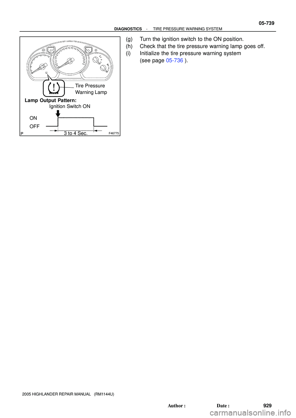
F46775
Tire Pressure
Warning Lamp
Lamp Output Pattern:
ON
OFFIgnition Switch ON
3 to 4 Sec.
F46779DLC3
Hand-Held
Tester
F46773
Tire Pressure Warning
Reset SwitchTire Pressure
Warning Lamp
ON
OFF Lamp Output Pattern:
� Normal Condition
Switch ON
ON
OFFSwitch
Operating
0.5 Sec.
0.5 Sec.
� System Malfunction 05-738
- DIAGNOSTICSTIRE PRESSURE WARNING SYSTEM
928 Author�: Date�:
2005 HIGHLANDER REPAIR MANUAL (RM1144U)
(h) Turn the ignition switch to the ON position.
(i) Check that the tire pressure warning lamp goes off.
(j) Initialize the tire pressure warning system
(see page 05-736).
2. TEST MODE (USING THE HAND-HELD TESTER)
(a) Connect the hand-held tester to the DLC3.
(b) Turn the ignition switch to the ON position.
(c) Select ºSIGNAL CHECKº, and proceed checking with the
hand-held tester.
(d) Press the tire pressure warning reset switch.
(e) Check that the tire pressure warning lamp comes on.
HINT:
�Unless (d) above is done, the tire pressure warning lamp
remains off while in test mode.
�When there is a problem with the tire pressure warning
system, the tire pressure warning lamp blinks at 0.5 se-
cond intervals.
If the lamp output result is not normal, proceed to the problem
symptoms table (see page 05-740).
(f) Turn the ignition switch off.
Page 2069 of 2572
F46775
Tire Pressure
Warning Lamp
Lamp Output Pattern:
ON
OFFIgnition Switch ON
3 to 4 Sec.
- DIAGNOSTICSTIRE PRESSURE WARNING SYSTEM
05-739
929 Author�: Date�:
2005 HIGHLANDER REPAIR MANUAL (RM1144U)
(g) Turn the ignition switch to the ON position.
(h) Check that the tire pressure warning lamp goes off.
(i) Initialize the tire pressure warning system
(see page 05-736).