Page 457 of 1897
BO2QK-01
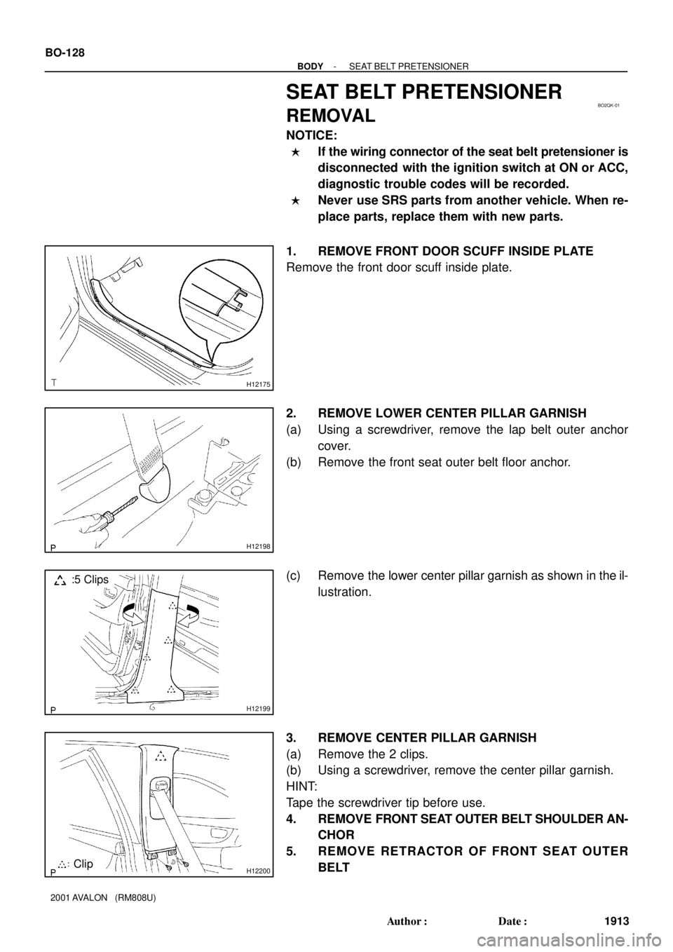
H12175
H12198
H12199
:5 Clips
H12200Clip BO-128
- BODYSEAT BELT PRETENSIONER
1913 Author�: Date�:
2001 AVALON (RM808U)
SEAT BELT PRETENSIONER
REMOVAL
NOTICE:
�If the wiring connector of the seat belt pretensioner is
disconnected with the ignition switch at ON or ACC,
diagnostic trouble codes will be recorded.
�Never use SRS parts from another vehicle. When re-
place parts, replace them with new parts.
1. REMOVE FRONT DOOR SCUFF INSIDE PLATE
Remove the front door scuff inside plate.
2. REMOVE LOWER CENTER PILLAR GARNISH
(a) Using a screwdriver, remove the lap belt outer anchor
cover.
(b) Remove the front seat outer belt floor anchor.
(c) Remove the lower center pillar garnish as shown in the il-
lustration.
3. REMOVE CENTER PILLAR GARNISH
(a) Remove the 2 clips.
(b) Using a screwdriver, remove the center pillar garnish.
HINT:
Tape the screwdriver tip before use.
4. REMOVE FRONT SEAT OUTER BELT SHOULDER AN-
CHOR
5. REMOVE RETRACTOR OF FRONT SEAT OUTER
BELT
Page 458 of 1897
H11075
- BODYSEAT BELT PRETENSIONER
BO-129
1914 Author�: Date�:
2001 AVALON (RM808U)
CAUTION:
Never disassemble the front seat outer belt.
NOTICE:
When removing the retractor of front seat outer belt, take
care not to pull the seat belt pretensioner wire harness.
(a) Disconnect the pretensioner connector as shown in the
illustration.
CAUTION:
When removing the seat belt pretensioner, work must be
started 90 seconds after the ignition switch is turned to the
ºLOCKº position and negative (-) terminal cable is discon-
nected from the battery.
(b) Remove the 2 bolts and retractor of front seat outer belt.
Page 549 of 1897

CHARGING SYSTEM
ON-VEHICLE INSPECT")
CH03U-03
Z11577
Except Maintenance-Free Battery
Z11556
Maintenance-Free Battery
Voltmeter
- CHARGINGCHARGING SYSTEM
CH-1
1274 Author�: Date�:
2001 AVALON (RM808U)
CHARGING SYSTEM
ON-VEHICLE INSPECTION
CAUTION:
�Check that the battery cables are connected to the
correct terminals.
�Disconnect the battery cables when the battery is giv-
en a quick charge.
�Do not perform tests with a high voltage insulation re-
sistance tester.
�Never disconnect the battery while the engine is run-
ning.
1. CHECK BATTERY ELECTROLYTE LEVEL
Check the electrolyte quantity of each cell.
Maintenance-Free Battery:
If under the lower level, replace the battery (or add distilled wa-
ter if possible). Check the charging system.
Except Maintenance-Free Battery:
If under the lower level, add distilled water.
2. Except Maintenance-Free Battery:
CHECK BATTERY SPECIFIC GRAVITY
Check the specific gravity of each cell.
Standard specific gravity: 1.25 - 1.29 at 20°C (68°F)
If the specific gravity is less than specification, charge the bat-
tery.
3. Maintenance-Free Battery:
CHECK BATTERY VOLTAGE
(a) After having driven the vehicle and in the case that 20
minutes have not passed after having stopped the en-
gine, turn the ignition switch ON and turn on the electrical
system (headlight, blower motor, rear defogger etc.) for
60 seconds to remove the surface charge.
(b) Turn the ignition switch OFF and turn off the electrical sys-
tems.
(c) Measure the battery voltage between the negative (-)
and positive (+) terminals of the battery.
Standard voltage: 12.5 - 12.9 V at 20°C (68°F)
If the voltage is less than specification, charge the battery.
Page 551 of 1897

�After installing a new belt, run the engine")
P19934
Z03473
Ammeter
Voltmeter
BatteryDisconnect Wire
from Terminal B
Generator
- CHARGINGCHARGING SYSTEM
CH-3
1276 Author�: Date�:
2001 AVALON (RM808U)
�After installing a new belt, run the engine for about 5 min-
utes and recheck the belt tension.
6. VISUALLY CHECK GENERATOR WIRING AND
LISTEN FOR ABNORMAL NOISES
(a) Check that the wiring is in good condition.
(b) Check that there is no abnormal noise from the generator
while the engine is running.
7. CHECK DISCHARGE WARNING LIGHT CIRCUIT
(a) Warm up the engine and then turn it off.
(b) Turn off all accessories.
(c) Turn the ignition switch ºONº. Check that the discharge
warning light is lit.
(d) Start the engine. Check that the light goes off.
If the light does not go off as specified, troubleshoot the dis-
charge light circuit.
8. INSPECT CHARGING CIRCUIT WITHOUT LOAD
HINT:
If a battery/generator tester is available, connect the tester to
the charging circuit as per the manufacturer's instructions.
(a) If a tester is not available, connect a voltmeter and amme-
ter to the charging circuit as follows:
�Disconnect the wire from terminal B of the genera-
tor, and connect it to the negative (-) probe of the
ammeter.
�Connect the positive (+) probe of the ammeter to
terminal B of the generator.
�Connect the positive (+) probe of the voltmeter to
terminal B of the generator.
�Ground the negative (-) probe of the voltmeter.
(b) Check the charging circuit as follows:
With the engine running from idling to 2,000 rpm, check
the reading on the ammeter and voltmeter.
Standard amperage: 10 A or less
Standard voltage: 13.2 -14.8 V
Page 565 of 1897
B09784
Driver Side J/B
Ignition
Relay
SF0DX-05
B09785
1
2 Ohmmeter
Continuity No Continuity
43
B09786
1
2 OhmmeterContinuity
Battery 43
- CHARGINGIGNITION RELAY (No.1)
CH-17
1290 Author�: Date�:
2001 AVALON (RM808U)
IGNITION RELAY (No.1)
INSPECTION
1. REMOVE IGNITION RELAY (Marking: IG1)
2. INSPECT IGNITION RELAY
(a) Inspect the relay continuity.
(1) Using an ohmmeter, check that there is no continu-
ity between terminals 1 and 2.
If there is continuity, replace the relay.
(2) Check that there is continuity between terminals 3
and 4.
If there is no continuity, replace the relay.
(b) Inspect the relay operation.
(1) Apply battery positive voltage across terminals 3
and 4.
(2) Using an ohmmeter, check that there is continuity
between terminals 1 and 2.
If there is no continuity, replace the relay.
3. REINSTALL IGNITION RELAY
Page 573 of 1897
B09054
CO0WU-01
B09056
B09434
B09432
B09435
- COOLINGELECTRIC COOLING FAN
CO-23
1216 Author�: Date�:
2001 AVALON (RM808U)
ELECTRIC COOLING FAN
ON-VEHICLE INSPECTION
1. CHECK COOLING FAN OPERATION WITH LOW TEM-
PERATURE (Below 83°C (181°F))
(a) Turn the ignition switch ON.
(b) Check that the cooling fans stop.
If not, check the cooling fan relays and ECT switches.
(c) Disconnect the No.1 ECT switch wire connector.
(d) Connect terminals on the No.1 ECT switch wire connec-
tor.
(e) Check that the No.1 cooling fan rotates at high speed.
If not, check the No.1 cooling fan relay and No.1 cooling fan.
(f) Reconnect the No.1 ECT switch connector.
(g) Disconnect the No.2 ECT switch connector.
(h) Ground terminal on the No.2 ECT switch wire harness
side connector.
(i) Check that the No.1 and No.2 cooling fans rotate at low
speed.
If not, check the No.2 cooling fan relay, No.3 cooling fan relay
and No.2 cooling fan.
(j) Reconnect the No.2 ECT switch connector.
Page 598 of 1897
F09799
ABS Actuator and ECU
A7 20
WA
Engine Room J/BEngine Room R/B No. 5
AM1
5 512
BIgnition Switch Driver Side J/B Multi Display
GAUGE No. 1
IG1 Relay10
1D
12
3 44
1C 3
1B1
1G W J/B No. 4
ABS
M65
M64
13
4F4
4DIE115
Battery FL Block
ALT 1
F8F61
BFL MAIN
IGB
B 7 A21
Active Light Relay
1 R-L
R-L
B-L ABS
D2
DLC215 4B
J/B No. 4
15 4A15
4HR-L
R-B R-B
4
W-R
IG1 AM12
7
IF1
1
2G1
2H
1
F10 W-BW-L
W-L 14
- DIAGNOSTICSANTI-LOCK BRAKE SYSTEM WITH ELECTRONIC
BRAKE FORCE DISTRIBUTION (EBD)DI-243
399 Author�: Date�:
2001 AVALON (RM808U)
ABS Warning Light Circuit
CIRCUIT DESCRIPTION
If the ECU detects trouble, the ABS warning light lights up and ABS control is prohibited at the same time.
At this time, the ECU records a DTC in memory.
Connecting terminals Tc and E
1 of the DLC1 makes the ABS warning light blink and output the DTC.
WIRING DIAGRAM
DI6NM-02
Page 601 of 1897
- DIAGNOSTICSANTI-LOCK BRAKE SYSTEM WITH ELECTRONIC
BRAKE FORCE DISTRIBUTION (EBD)DI-239
395 Author�: Date�:
2001 AVALON (RM808U)
4 Check battery positive voltage.
PREPARATION:
Start the engine.
CHECK:
Check the battery positive voltage.
OK:
Voltage: 10 - 16 V
NG Check and repair the charging system (See
page CH-1).
OK
5 Check operation of the ABS warning light.
PREPARATION:
(a) Turn the ignition switch OFF.
(b) Disconnect the connector from the ABS ECU.
(c) Turn the ignition switch ON.
CHECK:
Check the ABS warning light goes on.
OK Check and replace combination meter (See
page BE-2).
NG
6 Check for short circuit in harness and connector between active lamp relay and
ABS ECU (See page IN-30).
NG Repeir or replace harness or connector.
OK
Check and replace ABS ECU.