Page 229 of 1897
Insert already registered master key in the key cylinder
and turn the ignition switch ON.
Listing hand-held tester select master key registration.
Remove the master key.
Insert key to be registered in key cylinder.
(Security indicator blinks)
After 60 secs., additional master key is registered.
(Security indicator OFF)
The registration mode completes when pulling out the key
within 10 secs. and the brake pedal is depressed or after
indicator is off 10 secs. pass.Within 20 secs.
Within 10 secs.
HINT:
Please follow the screen of the hand-held tester for more detailed procedure.
- BODY ELECTRICALENGINE IMMOBILISER SYSTEM
BE-175
1779 Author�: Date�:
2001 AVALON (RM808U)
(2) Using hand-held tester:
Page 231 of 1897
Listing TOYOTA hand-held tester select sub-key regis-
tration.
Remove the master key.
Insert key to be registered in key cylinder.
(Security indicator blinks)
After 60 secs., additional sub-key is registered.
(Security indicator OFF)
The registration mode completes when pulling out the key
within 10 secs. and the brake pedal is depressed or after
indicator is off 10 secs. pass.Within 20 secs.
Within 10 secs.
Insert already registered master key in the key cylinder
and turn the ignition switch ON.
HINT:
Please follow the screen of the hand-held tester for more detailed procedure.
- BODY ELECTRICALENGINE IMMOBILISER SYSTEM
BE-177
1781 Author�: Date�:
2001 AVALON (RM808U)
(2) Using hand-held tester:
Page 233 of 1897
2. Require key code deletion from hand-held tester.
(Security indicator blinks)
3. Remove the master key.
HINT: END
Within 10 secs.
(Key code erased) 1. Insert already registered master key in the key cylinder
and turn the ignition switch ON.
� When the key cannot be pulled out in the step 3, key code deletion is canceled.
(Security indicator is OFF)
� Please follow the screen of the hand-held tester for more detailed procedure.
- BODY ELECTRICALENGINE IMMOBILISER SYSTEM
BE-179
1783 Author�: Date�:
2001 AVALON (RM808U)
(2) Using hand-held tester:
Page 247 of 1897

6. INSPECT D.R.L. NO.3 RELAY CIRCUIT
ConditionT")
I12785
1 2
3
4
5
1
I0574113
2 4
1 2
3
4
I12786
I12787
BE-20
- BODY ELECTRICALHEADLIGHT AND TAILLIGHT SYSTEM
1624 Author�: Date�:
2001 AVALON (RM808U)
6. INSPECT D.R.L. NO.3 RELAY CIRCUIT
ConditionTester connectionSpecified condition
Constant1 - 2, 3 - 4Continuity
Apply B+ between
terminals 1 and 2.3 - 5No continuity
If continuity is not as specified, replace the relay.
7. INSPECT D.R.L. NO.4 RELAY CIRCUIT
ConditionTester connectionSpecified condition
Constant3 - 4Continuity
Apply B+ between
terminals 3 and 4.1 - 2Continuity
If continuity is not as specified, replace the relay.
8. AUTO ON:
INSPECT AUTOMATIC LIGHT CONTROL
(a) Turn the ignition switch ON.
(b) Turn the light control switch to AUTO.
(c) Gradually cover the top of the sensor.
(d) Check the accessory lights and the headlights should turn
ON.
9. AUTO OFF:
INSPECT AUTOMATIC LIGHT CONTROL
(a) Gradually expose the sensor.
(b) Check the headlights and the accessory lights should turn
OFF.
10. INSPECT LIGHTS-OFF CONDITION
(a) Turn the ignition switch ON.
(b) Lights auto ON:
Gradually cover the top of the sensor.
(c) Check that the lights go off under the following conditions.
(1) Light control switch is OFF.
(2) The area surrounding the sensor gets bright.
(3) The driver's door is opened with the ignition switch
OFF.
11. INSPECT LIGHTS-ON CONDITION
(a) Open the driver's door while the ignition switch is OFF.
(b) Turn the light control switch to AUTO leaving the door
open and cover the top of the sensor, make sure that the
lights go on when the ignition switch is turned ON.
Page 248 of 1897

12. ADJUST AUTOMATIC LIGHT CONTROL SE")
N12536
ClockwiseCounter Clockwise
I01255
1
2 3 4
From Back Side
- BODY ELECTRICALHEADLIGHT AND TAILLIGHT SYSTEM
BE-21
1625 Author�: Date�:
2001 AVALON (RM808U)
12. ADJUST AUTOMATIC LIGHT CONTROL SENSOR
(a) Adjustment of the light control is performed by turning the
sensitivity knob on the sensor.
(b) This will be determined at what light condition the auto-
matic control will take place.
�If response is too quick, turn the knob counterclock-
wise.
�If response is too slow, turn the knob clockwise.
13. Connector connected:
INSPECT AUTOMATIC LIGHT CONTROL SENSOR
CIRCUIT
Connect the wire harness side connector to the sensor and in-
spect wire harness side connector from the back side, as
shown.
HINT:
�Ignition switch ON.
�Light control switch AUTO.
�Vehicle's surroundings are bright.
Tester connectionConditionSpecified condition
3 - GroundConstantContinuity
1 - GroundIgnition switch LOCK or ACCNo voltage
1 - GroundIgnition switch ON9.5 V or more
Vehicle is under the direct sun light.
(Sensor is not covered)Taillight and Headlight are ON.
If circuit is as specified, try replacing the sensor with a new one.
If the circuit is not as specified, inspect the circuit connected to
other parts.
Page 249 of 1897
I01254
Wire Harness Side
4 3 2 1 BE-22
- BODY ELECTRICALHEADLIGHT AND TAILLIGHT SYSTEM
1626 Author�: Date�:
2001 AVALON (RM808U)
14. Connector disconnected:
INSPECT AUTOMATIC LIGHT CONTROL SENSOR
CIRCUIT
Disconnect the connector from the sensor and inspect the con-
nector on the wire harness side, as shown in the table.
Tester connectionConditionSpecified condition
3 - GroundConstantContinuity
1 - GroundIgnition switch LOCK or ACCNo voltage
1 - GroundIgnition switch ONBattery positive voltage
4 - GroundIgnition switch LOCK or ACCNo voltage
4 - GroundIgnition switch ON5.2 - 9.0 V
If circuit is as specified, perform the inspection on the following
page.
If the circuit is not as specified, inspect the circuit connected to
other parts.
Page 250 of 1897
BE0HV-04
I12524
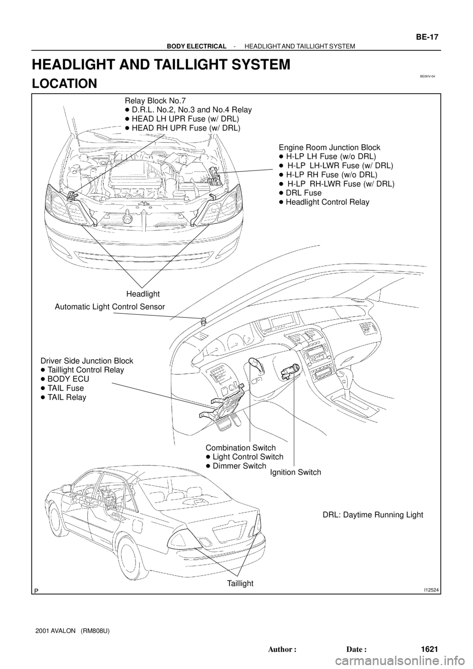
Relay Block No.7
� D.R.L. No.2, No.3 and No.4 Relay
� HEAD LH UPR Fuse (w/ DRL)
� HEAD RH UPR Fuse (w/ DRL)
Engine Room Junction Block
� H-LP LH Fuse (w/o DRL)
� H-LP LH-LWR Fuse (w/ DRL)
� H-LP RH Fuse (w/o DRL)
� H-LP RH-LWR Fuse (w/ DRL)
� DRL Fuse
� Headlight Control Relay
Headlight
Driver Side Junction Block
� Taillight Control Relay
� BODY ECU
� TAIL Fuse
� TAIL Relay
Ignition Switch
Taillight
Combination Switch
� Light Control Switch
� Dimmer Switch
Automatic Light Control Sensor
DRL: Daytime Running Light
- BODY ELECTRICALHEADLIGHT AND TAILLIGHT SYSTEM
BE-17
1621 Author�: Date�:
2001 AVALON (RM808U)
HEADLIGHT AND TAILLIGHT SYSTEM
LOCATION
Page 254 of 1897
BE1DI-01
I01256
1 3
867 4
5 2
LOCKACC
START
ON
N20125
ONOFF
1 2
I05741
1 2
3 4
1
2 3
4
BE-16- BODY ELECTRICALIGNITION SWITCH AND KEY UNLOCK WARNING
SWITCH
1620 Author�: Date�:
2001 AVALON (RM808U)
INSPECTION
1. INSPECT IGNITION SWITCH CONTINUITY
Switch positionTester connectionSpecified condition
LOCK-No continuity
ACC2 - 3Continuity
ON2 - 3 - 4
6 - 7Continuity
START1 - 2 - 4
6 - 7 - 8Continuity
If continuity is not as specified, replace the switch.
2. INSPECT KEY UNLOCK WARNING SWITCH CONTI-
NUITY
ConditionTester connectionSpecified condition
Switch OFF
(Key removed) -No continuity
Switch ON
(Key set)1 - 2Continuity
If continuity is not as specified, replace the switch.
3. INSPECT IG1 RELAY CONTINUITY
ConditionTester connectionSpecified condition
Constant3 - 4Continuity
Apply B+ between
terninal 3 and 41 - 2Continuity
If continuity is not as specified, replace the switch.


After 60 secs., additional sub-key is reg")

3. Remove the master key.
HINT: END
Within 10 secs.
(Key code erased) 1. Insert already registered ma")