Page 437 of 1897
H12119
- BODYREAR DOOR
BO-21
1806 Author�: Date�:
2001 AVALON (RM808U)
HINT:
At the time of reassembly, please refer to the following item.
Apply MP grease to the sliding and rotating parts of the door
lock.
16. REMOVE OUTSIDE HANDLE
Remove the 2 bolts and outside handle.
Torque: 5.4 N´m (55 kgf´cm, 48 in.´lbf)
Page 452 of 1897
 or moreSSTBattery
- BODYSEAT BELT PRETENSIONER
BO-133
1918 Author�: Date�:
2001 AVALON (RM808U)
(2) Connect the 2 SST, then connect them to the seat
belt")
H11079
SST SST
Battery
R13455
10 m (33 ft) or moreSSTBattery
- BODYSEAT BELT PRETENSIONER
BO-133
1918 Author�: Date�:
2001 AVALON (RM808U)
(2) Connect the 2 SST, then connect them to the seat
belt pretensioner.
SST 09082-00700, 09082-00740
NOTICE:
To avoid damaging the SST connector and wire harness,
do not lock the secondary lock of the twin lock.
(3) Move the SST to at least 10 m (33 ft) away from the
front of the vehicle.
(4) Close all the doors and windows of the vehicle.
NOTICE:
Take care not to damage the SST wire harness.
(5) Connect the SST red clip to the battery positive (+)
terminal and the black clip to the negative (-) termi-
nal.
(d) Activate the seat belt pretensioner.
(1) Confirm that no one is inside the vehicle or within 10
m (33 ft) area around the vehicle.
(2) Press the SST activation switch and activate the
seat belt pretensioner.
HINT:
The seat belt pretensioner operates simultaneously as the LED
of the SST activation switch lights up.
(e) Dispose of the front seat outer belt (with seat belt preten-
sioner).
CAUTION:
�The front seat outer belt is very hot when the seat belt
pretensioner is activated, so leave it alone for at least
30 minutes after activation.
�Use gloves and safety glasses when handling a front
seat outer belt with the activated seat belt pretension-
er.
�Always wash your hands with water after completing
the operation.
�Do not apply water, etc. to a front seat outer belt with
the activated seat belt pretensioner.
HINT:
When scrapping a vehicle, activate the seat belt pretensioner
and scrap the vehicle with the activated front seat outer belt still
installed.
2. ACTIVATION WHEN DISPOSING OF FRONT SEAT
OUTER BELT ONLY
NOTICE:
�When disposing of the front seat outer belt (with seat
belt pretensioner) only, never use the customer's ve-
hicle to activate the seat belt pretensioner.
Page 793 of 1897
I13651
BKA A
J11
J/C W-B BA18W-B43 D15
Door Unlock
Detection Switch Rear LH
L-OBA19
L-O66
3E 3F
3F19L-O
L-O L-O
L-OBody ECU
5
B5 LSR
10
IM2 BB19
21
W-B
Door Unlock
Detection Switch Rear RHD16
8
BB1
W-B
BM J/B No. 3
- DIAGNOSTICSBODY CONTROL SYSTEM
DI-643
799 Author�: Date�:
2001 AVALON (RM808U)
Rear door unlock detection switch circuit
CIRCUIT DESCRIPTION
The door unlock detection switch is built in the door lock motor assembly. This switch is ON when the door
lock knob is in the unlock position and OFF when the lock knob is in the lock position. The ECU detects the
door lock knob conditions is this circuit. It is used as one of the operating conditions for the key confinement
prevention function.
WIRING DIAGRAM
DI6LR-01
Page 794 of 1897
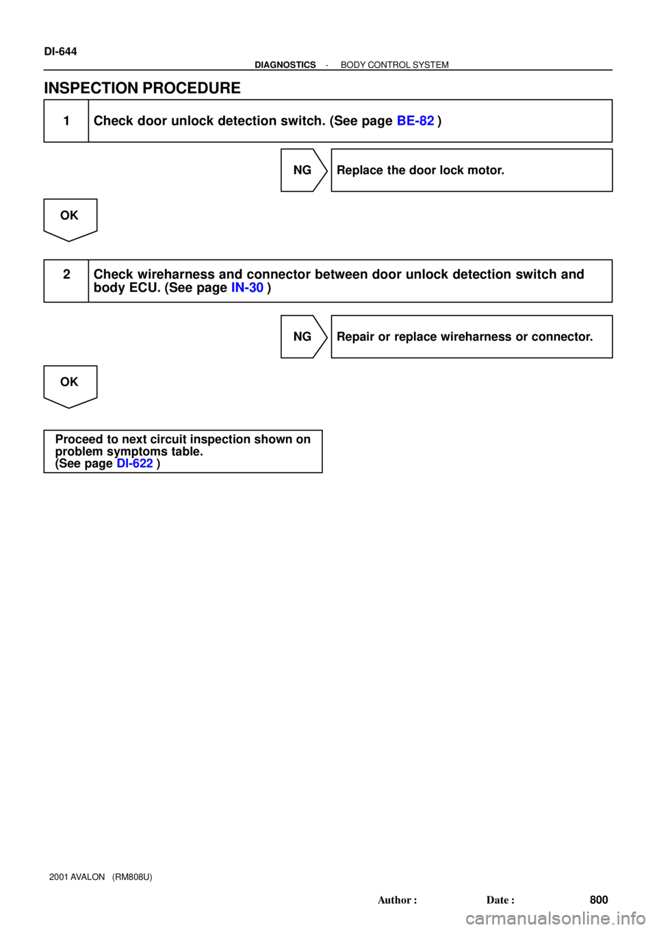
DI-644
- DIAGNOSTICSBODY CONTROL SYSTEM
800 Author�: Date�:
2001 AVALON (RM808U)
INSPECTION PROCEDURE
1 Check door unlock detection switch. (See page BE-82)
NG Replace the door lock motor.
OK
2 Check wireharness and connector between door unlock detection switch and
body ECU. (See page IN-30)
NG Repair or replace wireharness or connector.
OK
Proceed to next circuit inspection shown on
problem symptoms table.
(See page DI-622)
Page 795 of 1897
I14523
Body ECU
L-RL-B
L-W 3 L-B
219
IB21
B5ACTD B5 15
ACT-
L-B 10
L-B2
B5ACT+
5
D17
Door Lock Motor
Front LH IB2 L-R
C C
C CL-B
J3
J/C 11
IM2IA1 L-B
5 10 BA1
BB1 L-B
L-BL-BL-R 10
IN1D18
Door Lock Motor
Front RH
11
IN1L-R AA
AA L-R L-R
L-R 13
IA1
L-R
L-RL-B L-R
5
BA1 2 D15
Door Lock Motor
Rear LH D16
Door Lock Motor
Rear RH
1 34
BB112
IM2J2
J/C
5
6A
- DIAGNOSTICSBODY CONTROL SYSTEM
DI-641
797 Author�: Date�:
2001 AVALON (RM808U)
Door lock motor circuit
WIRING DIAGRAM
DI6LQ-01
Page 796 of 1897
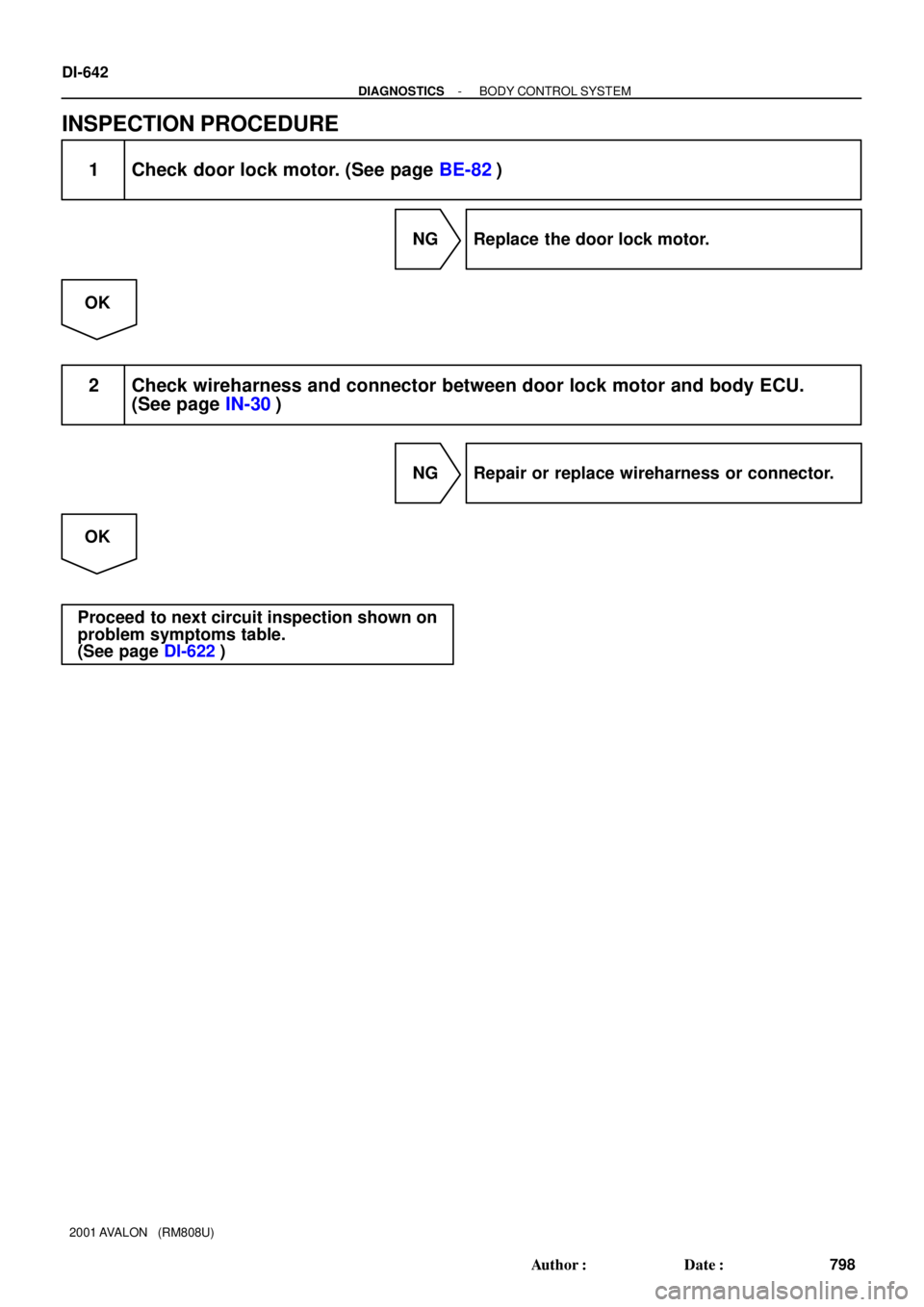
DI-642
- DIAGNOSTICSBODY CONTROL SYSTEM
798 Author�: Date�:
2001 AVALON (RM808U)
INSPECTION PROCEDURE
1 Check door lock motor. (See page BE-82)
NG Replace the door lock motor.
OK
2 Check wireharness and connector between door lock motor and body ECU.
(See page IN-30)
NG Repair or replace wireharness or connector.
OK
Proceed to next circuit inspection shown on
problem symptoms table.
(See page DI-622)
Page 804 of 1897
I13641
P-LP-LP-LP-L
P-L
P-L
P-L 1
4F
4D
4C 11
7
1D 1J9 DOME
W-L
1
11 1
1
12C DCC
2
2G
B
F7 F6FL Block
FL MAINB
BatteryV11
Vanity Light RH
2
V10
Vanity Light RH
2W-B
W-B
2
3P9
Personal Light
ON
OFF
DOOR
I17
Interior Light
ON
OFF
DOOR
4
4D
R-B13
4F
R-BG-R
G-R3
1C5
ILL
10
1D2 GAUGE No. 1IG1 RELAY
11
4
3 4
1C 1B3 1GMulti Display
3
42
2 M7
M6M7
M6 Open Door
Driver Seat Belt
10
M7R
G-W
G-R25
B5
B5
B523
11AJAR
DBEW
PBEW
FL MAIN FL Block
ALT W
1
F101
F6
F81B
B-L
Battery
11
2H 2G W-B W-R
4
IG1 AM1 I15
Ignition Switch
2
W-L7
IF1
IG
AM1
21
55W-L
B2BLBody ECU
IG1 5
G-R
IG1
G-R 11 4C10
P-L
2
1
I14
Ignition
Key
Cylinder
LightG-R Engine Room J/B
Engine Room R/B No.5Engine Room J/B J/B No.4
Driver Side J/B
Passenger
Seat Belt
Driver Side J/B J/B No.4
Driver Side J/B
8W-B
1
G-R
IG1
DI-656
- DIAGNOSTICSBODY CONTROL SYSTEM
812 Author�: Date�:
2001 AVALON (RM808U)
WIRING DIAGRAM
Page 810 of 1897
I13654
L9
Luggage Compartment
Light Switch
1
R-W12 12
4E 4C
RBody ECU
6
B4
LGC
2
L7
Luggage Compartment
Door Unlock MotorL4
IK1
L25
B4TR+ J/B No. 4
- DIAGNOSTICSBODY CONTROL SYSTEM
DI-649
805 Author�: Date�:
2001 AVALON (RM808U)
Luggage opener motor circuit
WIRING DIAGRAM
DI6LU-01