Page 1385 of 1897

Join
Line
Join
Line
Length = 460 mm
(18.11 in.)
A04693
SST
P18816
- ENGINE MECHANICALTIMING BELT
EM-25
1009 Author�: Date�:
2001 AVALON (RM808U)
14. INSTALL NO.1 TI")
P12982
Length = 240 mm (9.45 in.)
Join
Line
Join
Line
Length = 460 mm
(18.11 in.)
A04693
SST
P18816
- ENGINE MECHANICALTIMING BELT
EM-25
1009 Author�: Date�:
2001 AVALON (RM808U)
14. INSTALL NO.1 TIMING BELT COVER
(a) Check that the timing belt cover gaskets have cracks or
peeling, etc.
If the gasket has cracks or peeling, etc., replace it using these
steps:
�Using a screwdriver and gasket scraper, remove all
the old gasket material.
�Thoroughly clean all components to remove all the
loose material.
�Remove the backing paper from a new gasket and
install the gasket evenly to the part of the timing belt
cover shaded black in the illustration.
NOTICE:
When joining 2 gaskets, do not leave a gap between them.
Cut off any excess gasket.
�After installing the gasket, press down on it so that
the adhesive firmly sticks to the timing belt cover.
(b) Install the timing belt cover with the 4 bolts.
Torque: 8.5 N´m (85 kgf´cm, 74 in.´lbf)
15. INSTALL CRANKSHAFT PULLEY
(a) Align the pulley set key with the key groove of the pulley,
and slide on the pulley.
(b) Using SST, install the pulley bolt.
SST 09213-54015 (91651-60855), 09330-00021
Torque: 215 N´m (2,200 kgf´cm, 159 ft´lbf)
16. INSTALL NO.2 GENERATOR BRACKET
Install the generator bracket with the pivot bolt and nut. Do not
tighten the bolt yet.
Torque: (Nut): 28 N´m (290 kgf´cm, 21 ft´lbf)
17. INSTALL NO.2 RH ENGINE MOUNTING BRACKET
AND ENGINE MOVING CONTROL ROD
(See page EM-77)
18. CONNECT GROUND STRAP CONNECTORS
19. CONNECT ENGINE COOLANT RESERVOIR HOSE TO
WATER OUTLET
20. INSTALL PS PUMP DRIVE BELT
21. INSTALL GENERATOR DRIVE BELT
(See page CH-16)
22. INSTALL RH FENDER APRON SEAL
23. INSTALL RH FRONT WHEEL
24. VEHICLE ROAD TEST
Check for abnormal noise, shock, slippage, correct shift points
and smoothly operation.
Page 1387 of 1897
P18820
A05050
Clamp
Clamp
P18814
P18808
A05052
EM-16
- ENGINE MECHANICALTIMING BELT
1000 Author�: Date�:
2001 AVALON (RM808U)
10. REMOVE NO.1 TIMING BELT COVER
Remove the 4 bolts and timing belt cover.
11. REMOVE TIMING BELT GUIDE
12. REMOVE NO.2 TIMING BELT COVER
(a) Disconnect the engine wire protector clamps from the
No.3 timing belt cover.
(b) Remove the 5 bolts and timing belt cover.
13. REMOVE RH ENGINE MOUNTING BRACKET
Remove the 2 bolts, nut and mounting bracket.
14. SET NO.1 CYLINDER TO TDC/COMPRESSION
(a) Temporarily install the crankshaft pulley bolt to the crank-
shaft.
(b) Turn the crankshaft, and align the timing marks of the
crankshaft timing pulley and oil pump body.
NOTICE:
Always turn the crankshaft clockwise.
(c) Check that timing marks of the camshaft timing pulleys
and No.3 timing belt cover are aligned.
If not, turn the crankshaft 1 revolution (360°).
(d) Remove the crankshaft pulley bolt.
Page 1388 of 1897

15. IF REUSING TIMING BELT, CHECK INSTALLATION
MARKS ON TIMING BELT
Che")
A01804
A05053
A05054
SST RH
A05056
SSTLH
A05055
- ENGINE MECHANICALTIMING BELT
EM-17
1001 Author�: Date�:
2001 AVALON (RM808U)
15. IF REUSING TIMING BELT, CHECK INSTALLATION
MARKS ON TIMING BELT
Check that there are 3 installation marks and front mark on the
timing belt.
If the installation and front marks have disappeared, before re-
moving the timing belt, place 3 new installation marks on the
timing belt to match the timing marks of the timing pulleys, and
place a new front mark on the timing belt.
16. REMOVE TIMING BELT TENSIONER
Alternately loosen the 2 bolts, and remove them, the tensioner
and dust boot.
17. REMOVE TIMING BELT
18. REMOVE CAMSHAFT TIMING PULLEYS
(a) Using SST, remove the bolt and RH timing pulley.
SST 09249-63010, 09960-10010 (09962-01000,
09963-01000)
(b) Using SST, remove the LH timing pulley.
SST 09960-10010 (09962-01000, 09963-01000)
HINT:
Arrange the camshaft timing pulleys (RH and LH sides).
19. REMOVE NO.2 IDLER PULLEY
Remove the bolt and idler pulley.
Page 1390 of 1897

VALVE CLEARANCE
INSPECTION
HINT:
Inspect and adjust")
EM03V-03
P18805
A05273
RH EX
RH IN
LH IN
LH EX 3 3
11Front
2266 EM-4
- ENGINE MECHANICALVALVE CLEARANCE
988 Author�: Date�:
2001 AVALON (RM808U)
VALVE CLEARANCE
INSPECTION
HINT:
Inspect and adjust the valve clearance when the engine is cold.
1. REMOVE RH FENDER APRON SEAL
2. DRAIN ENGINE COOLANT
3. REMOVE V-BANK COVER
(a) Using a 5 mm hexagon wrench, remove the 3 cap nuts.
(b) Loosen the V-bank cover fastener counterclockwise.
(c) Remove the V-bank cover.
4. REMOVE AIR INTAKE CHAMBER ASSEMBLY (See
page EM-31)
5. REMOVE IGNITION COILS
6. DISCONNECT UPPER RADIATOR HOSE FROM WA-
TER OUTLET
7. REMOVE CYLINDER HEAD COVERS
(See page EM-31)
8. SET NO.1 CYLINDER TO TDC/COMPRESSION
(a) Turn the crankshaft pulley, and align its groove with the
timing mark º0º of the No.1 timing belt cover.
(b) Check that the valve lifters on the No.1 (IN and EX) are
loose.
If not, turn the crankshaft 1 revolution (360°) and align the mark
as above.
9. INSPECT VALVE CLEARANCE
(a) Check only those valves indicated in the illustration.
(1) Using a feeler gauge, measure the clearance be-
tween the valve lifter and camshaft.
(2) Record out of specification valve clearance mea-
surements. They will be used later to determine the
required replacement adjusting shim.
Valve clearance (Cold):
Intake0.15 - 0.25 mm (0.006 - 0.010 in.)
Exhaust0.25 - 0.35 mm (0.010 - 0.014 in.)
Page 1391 of 1897
A05272
RH EX
RH IN
LH IN
LH EX 33
22Front5 5
44
A05274
RH EX
RH IN
LH IN
LH EX Front
55
44
66 11
P12919
Upward
Notch
- ENGINE MECHANICALVALVE CLEARANCE
EM-5
989 Author�: Date�:
2001 AVALON (RM808U)
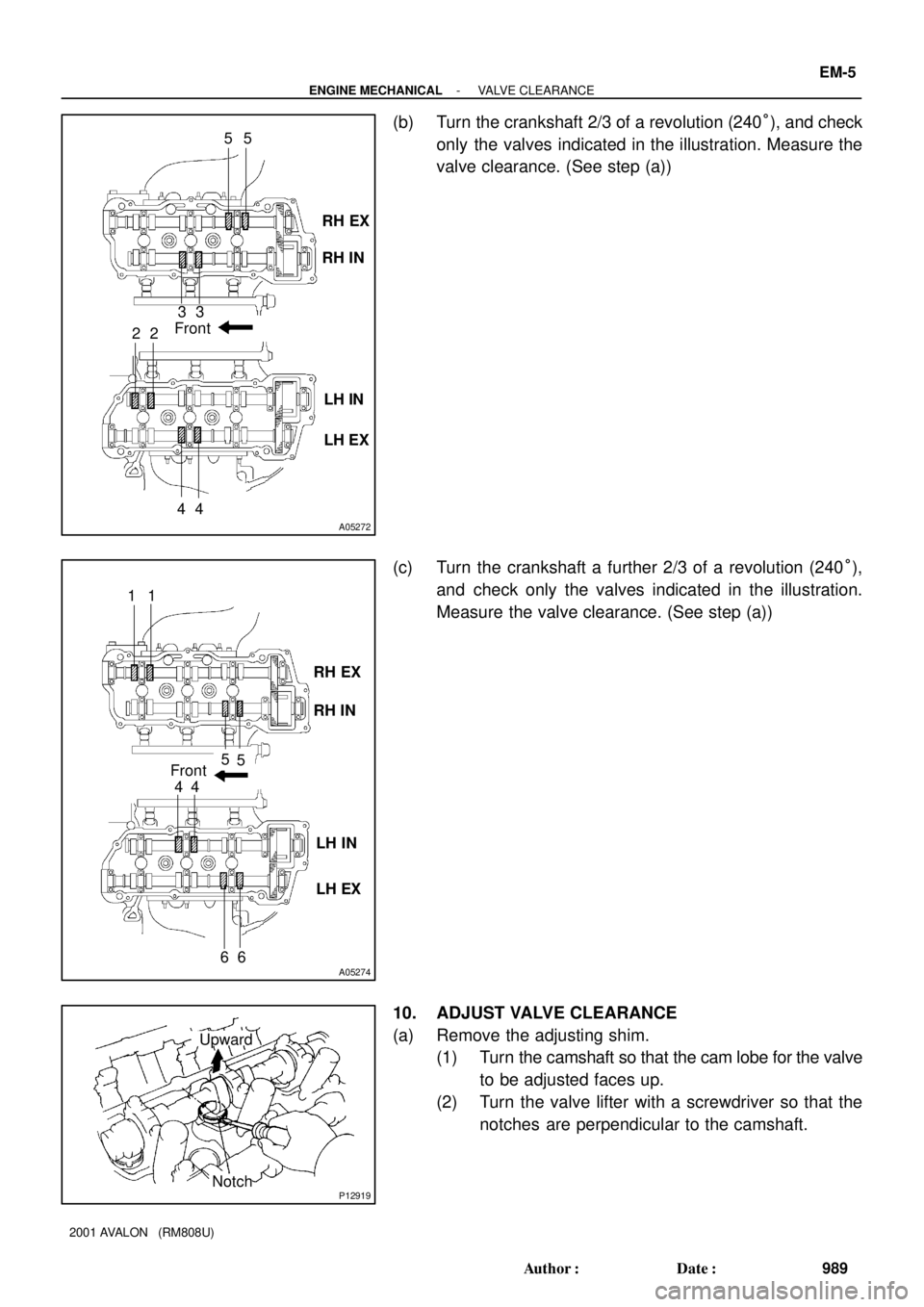
(b) Turn the crankshaft 2/3 of a revolution (240°), and check
only the valves indicated in the illustration. Measure the
valve clearance. (See step (a))
(c) Turn the crankshaft a further 2/3 of a revolution (240°),
and check only the valves indicated in the illustration.
Measure the valve clearance. (See step (a))
10. ADJUST VALVE CLEARANCE
(a) Remove the adjusting shim.
(1) Turn the camshaft so that the cam lobe for the valve
to be adjusted faces up.
(2) Turn the valve lifter with a screwdriver so that the
notches are perpendicular to the camshaft.
Page 1393 of 1897
P12979
SST (A)
SST (B)
- ENGINE MECHANICALVALVE CLEARANCE
EM-7
991 Author�: Date�:
2001 AVALON (RM808U)
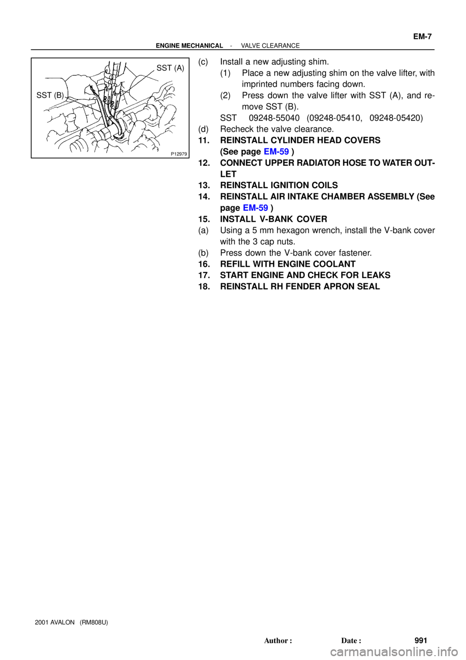
(c) Install a new adjusting shim.
(1) Place a new adjusting shim on the valve lifter, with
imprinted numbers facing down.
(2) Press down the valve lifter with SST (A), and re-
move SST (B).
SST 09248-55040 (09248-05410, 09248-05420)
(d) Recheck the valve clearance.
11. REINSTALL CYLINDER HEAD COVERS
(See page EM-59)
12. CONNECT UPPER RADIATOR HOSE TO WATER OUT-
LET
13. REINSTALL IGNITION COILS
14. REINSTALL AIR INTAKE CHAMBER ASSEMBLY (See
page EM-59)
15. INSTALL V-BANK COVER
(a) Using a 5 mm hexagon wrench, install the V-bank cover
with the 3 cap nuts.
(b) Press down the V-bank cover fastener.
16. REFILL WITH ENGINE COOLANT
17. START ENGINE AND CHECK FOR LEAKS
18. REINSTALL RH FENDER APRON SEAL
Page 1402 of 1897
B09783
Engine Room J/B
Ignition
Relay
SF0DX-04
S04970
Continuity
No ContinuityOhmmeter
2
35 Ohmmeter
1
S04969ContinuityOhmmeter 2
35 1
Battery IG-10
- IGNITIONIGNITION RELAY (No.2)
1253 Author�: Date�:
2001 AVALON (RM808U)
IGNITION RELAY (No.2)
INSPECTION
1. REMOVE IGNITION RELAY (Marking: IG2)
2. INSPECT IGNITION RELAY
(a) Inspect the relay continuity.
(1) Using an ohmmeter, check that there is continuity
between terminals 1 and 2.
If there is no continuity, replace the relay.
(2) Check that there is no continuity between terminals
3 and 5.
If there is continuity, replace the relay.
(b) Inspect the relay operation.
(1) Apply battery positive voltage across terminals 1
and 2.
(2) Using an ohmmeter, check that there is continuity
between terminals 3 and 5.
If there is no continuity, replace the relay.
3. REINSTALL IGNITION RELAY
Page 1403 of 1897

IG0DL-02
SPARK TEST
CHECK CONNECTIONS OF IGNITION COIL (WITH
CHECK POWER SUPPLY TO IGNITION COILS (WITH
1. Turn ignition switch to ON.
2. Check that there is battery positive voltage at ignition
CHECK RESISTANCE OF SENSORS
Resistance: Cold Hot
Camshaft position sensor
Crankshaft position sensor835 - 1,400 W
1,630 - 2,740 W1,060 - 1,645 W
2,065 - 3,225 W
CHECK IGT SIGNAL FROM ECM (See page DI-1 17)
TRY ANOTHER IGNITION COIL (WITH IGNITER) IGNITER) CONNECTORS
coil positive (+) terminal.
(See steps 4 and 5)NO
OK
NO
OK
OK
BAD
OK
BAD
BAD
BAD
Connect securely.
Replace ignition coil (with igniter).
Check wiring between ignition switch to
Replace camshaft position sensor.
Check wiring between ECM and ignition ignition coils (with igniters).
coils (with igniters), and then try another CHANGE IT TO NORMAL IGNITION COIL (WITH IGNITER)
AND PERFORM SPARK TEST AGAIN
Replace crankshaft position sensor.
ECM. OK IGNITER)
- IGNITIONIGNITION SYSTEM
IG-1
1244 Author�: Date�:
2001 AVALON (RM808U)
IGNITION SYSTEM
ON-VEHICLE INSPECTION
NOTICE:
ºColdº and ºHotº in these sentences express the tempera-
ture of the coils themselves. ºColdº is from -10°C (14°F) to
50°C (122°F) and ºHotº is from 50°C (122°F) to 100°C
(212°F).
1. INSPECT SPARK TEST
Check that the spark occurs.
(1) Remove the ignition coils (with igniters) (See page
IG-5).
(2) Remove the spark plugs.
(3) Install the spark plug to the ignition coil, and connect
the ignition coil connector.
(4) Ground the spark plug.
(5) See if spark occurs while engine is being cranked.
NOTICE:
To prevent gasoline from being injected from injectors dur-
ing this test, crank the engine for no more than 5 - 10 se-
conds at time.
If the spark does not occur, do the test as follows: