Page 1310 of 1897

(b")
A10530
A09696
Less than 6 mm
A10529
P12753
10 11
12 13
14
151
162
3
45
6
7
89
P25741
Painted Mark
Front90°
90° EM-104
- ENGINE MECHANICALCYLINDER BLOCK
1088 Author�: Date�:
2001 AVALON (RM808U)
(b) Temporarily place the 4 main bearing caps level and let
them in their proper locations.
(c) Apply a light coat of engine oil on the threads and under
the main bearing cap bolts for the 12 pointed head.
(d) Temporarily install the 8 main bearing cap bolts to the in-
side positions.
(e) Insert the main bearing cap with your hand until the clear-
ance between the main bearing cap and the cylinder
block will become less than 6 mm (0.23 in.) by making the
2 internal main bearing cap bolts as a guide.
(f) Using a plastic-faced hammer, lightly tap the bearing cap
to ensure a proper fit.
8. INSTALL 12 POINTED HEAD MAIN BEARING CAP
BOLTS
HINT:
�The main bearing cap bolts are tightened in 2 progressive
steps (steps (b) and (d)).
�If any of the main bearing cap bolts is broken or deformed,
replace it.
(a) Apply a light coat of engine oil on the threads and under
the main bearing cap bolts.
(b) Install and uniformly tighten the 16 main bearing cap bolts
in several passes and in the sequence shown.
Torque: 22 N´m (225 kgf´cm, 16 ft´lbf)
If any of the main bearing cap bolts does not meet the torque
specification, replace the main bearing cap bolt.
(c) Mark the front of the main bearing cap bolts with paint.
(d) Retighten the main bearing cap bolts by 90° in the numer-
ical order shown.
(e) Check that the painted mark is now at a 90° angle to the
front.
Page 1311 of 1897

Front Mark
(Cavity)RH Piston
LH Piston
P12699
P12801
Front
Protrusion
- ENGINE MECHANICALCYLINDER BLOCK
EM-105
1089 Author�: Date�:
2001 AVALON (RM808U")
P12586
1
2
34
567
8
A10528
Front Mark
(Cavity)
Front Mark
(Cavity)RH Piston
LH Piston
P12699
P12801
Front
Protrusion
- ENGINE MECHANICALCYLINDER BLOCK
EM-105
1089 Author�: Date�:
2001 AVALON (RM808U)
9. INSTALL HEXAGON HEAD MAIN BEARING CAP
BOLTS
(a) Install a new seal washer to the main bearing cap bolt.
(b) Install and uniformly tighten the 8 main bearing cap bolts
in several passes and in the sequence shown.
Torque: 27 N´m (275 kgf´cm, 20 ft´lbf)
10. CHECK CRANKSHAFT THRUST CLEARANCE
(See page EM-83)
11. INSTALL PISTON AND CONNECTING ROD AS-
SEMBLES
Using a piston ring compressor, push the correctly numbered
piston and connecting rod assemblies into each cylinder with
the front mark of the piston facing forward.
HINT:
The shape of the piston varies for the RH and LH banks. The
RH piston is marked with ºRº, the LH piston with ºLº.
12. PLACE CONNECTING ROD CAP ON CONNECTING
ROD
(a) Match the numbered connecting rod cap with the con-
necting rod.
(b) Align the pin dowels of the connecting rod cap with the
pins of the connecting rod, and install the connecting rod.
(c) Check that the protrusion of the connecting rod cap is fac-
ing in the correct direction.
13. INSTALL CONNECTING ROD CAP BOLTS
HINT:
�The connecting rod cap bolts are tightened in 2 progres-
sive steps (steps (b) and (d)).
�If any of the connecting rod cap bolts is broken or de-
formed, replace it.
Page 1312 of 1897

(a) Apply a light coat of engine oil")
P12697
P25743
Painted Mark
Front90°
90°
P12911
Seal Width
2 - 3 mm A
BA
B EM-106
- ENGINE MECHANICALCYLINDER BLOCK
1090 Author�: Date�:
2001 AVALON (RM808U)
(a) Apply a light coat of engine oil on the threads and under
the heads of the connecting rod cap bolts.
(b) Install and alternately tighten the 2 connecting rod cap
bolts in several passes.
Torque: 24.5 N´m (250 kgf´cm, 18 ft´lbf)
If any of the connecting rod cap bolts does not meet the torque
specification, replace the connecting rod cap bolts.
(c) Mark the front of the connecting cap bolts with paint.
(d) Retighten the cap bolts by 90° as shown.
(e) Check that the painted mark is now at a 90° angle to the
front.
(f) Check that the crankshaft turns smoothly.
14. CHECK CONNECTING ROD THRUST CLEARANCE
(See page EM-83)
15. INSTALL REAR OIL SEAL RETAINER
(a) Remove any old packing (FIPG) material and be careful
not to drop any oil on the contact surfaces of the oil seal
retainer and cylinder block.
�Using a razor blade and gasket scraper, remove all
the oil packing (FIPG) material from the gasket sur-
faces and sealing grooves.
�Thoroughly clean all components to remove all the
loose material.
�Using a non-residue solvent, clean both sealing
surfaces.
(b) Apply seal packing to the oil seal retainer as shown in the
illustration.
Seal packing: Part No. 08826-00080 or equivalent
�Install a nozzle that has been cut to a 2 - 3 mm (0.08
- 0.12 in.) opening.
�Parts must be assembled within 3 minutes of ap-
plication. Otherwise the material must be removed
and reapplied.
�Immediately remove nozzle from the tube and rein-
stall cap.
(c) Install the oil seal retainer with the 6 bolts. Uniformly tight-
en the bolt in several passes and in the sequence shown.
Torque: 8 N´m (80 kgf´cm, 69 in.´lbf)
16. INSTALL CYLINDER BLOCK SIDE COVER
Install a new gasket and the cylinder block side cover with the
3 bolts and 2 nuts.
Torque: 9 N´m (90 kgf´cm, 78 in.´lbf)
Page 1316 of 1897
EM0ZP-02
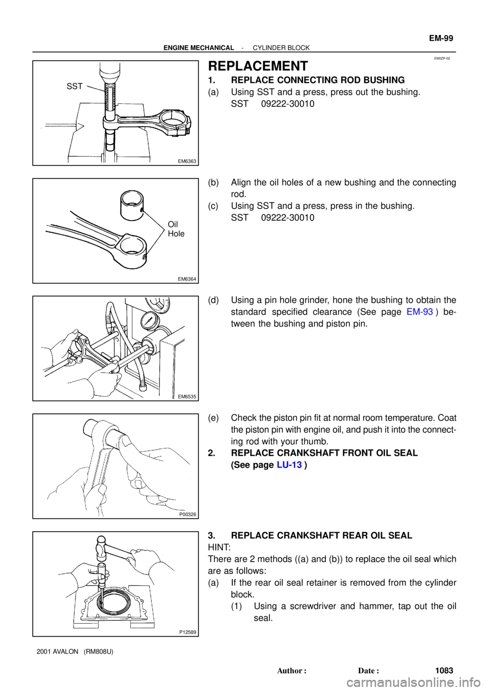
EM6363
SST
EM6364
Oil
Hole
EM6535
P00326
P12589
- ENGINE MECHANICALCYLINDER BLOCK
EM-99
1083 Author�: Date�:
2001 AVALON (RM808U)
REPLACEMENT
1. REPLACE CONNECTING ROD BUSHING
(a) Using SST and a press, press out the bushing.
SST 09222-30010
(b) Align the oil holes of a new bushing and the connecting
rod.
(c) Using SST and a press, press in the bushing.
SST 09222-30010
(d) Using a pin hole grinder, hone the bushing to obtain the
standard specified clearance (See page EM-93) be-
tween the bushing and piston pin.
(e) Check the piston pin fit at normal room temperature. Coat
the piston pin with engine oil, and push it into the connect-
ing rod with your thumb.
2. REPLACE CRANKSHAFT FRONT OIL SEAL
(See page LU-13)
3. REPLACE CRANKSHAFT REAR OIL SEAL
HINT:
There are 2 methods ((a) and (b)) to replace the oil seal which
are as follows:
(a) If the rear oil seal retainer is removed from the cylinder
block.
(1) Using a screwdriver and hammer, tap out the oil
seal.
Page 1326 of 1897
P12755
A05231
A05227
EM0580
- ENGINE MECHANICALCYLINDER HEAD
EM-43
1027 Author�: Date�:
2001 AVALON (RM808U)
5. CLEAN VALVE GUIDE BUSHINGS
Using a valve guide bushing brush and solvent, clean all the
guide bushings.
6. INSPECT FOR FLATNESS
Using a precision straight edge and feeler gauge, measure the
surfaces contacting the cylinder block and the manifolds for
warpage.
Maximum warpage: 0.10 mm (0.0039 in.)
If warpage is greater than maximum, replace the cylinder head.
7. INSPECT FOR CRACKS
Using a dye penetrant, check the combustion chamber, intake
ports, exhaust ports and cylinder block contact surface for
cracks.
If cracked, replace the cylinder head.
8. CLEAN VALVES
(a) Using a gasket scraper, chip off any carbon from the valve
head.
(b) Using a wire brush, thoroughly clean the valve.
Page 1327 of 1897

9. INSPECT VALVE STEMS AND GUIDE BUSHINGS
(a) Using a caliper gau")
P12754
Z00052
Z00054
44.5°
EM0181
Margin Thickness EM-44
- ENGINE MECHANICALCYLINDER HEAD
1028 Author�: Date�:
2001 AVALON (RM808U)
9. INSPECT VALVE STEMS AND GUIDE BUSHINGS
(a) Using a caliper gauge, measure the inside diameter of the
guide bushing.
Bushing inside diameter:
5.510 - 5.530 mm (0.2169 - 0.2177 in.)
(b) Using a micrometer, measure the diameter of the valve
stem.
Valve stem diameter:
Intake5.470 - 5.485 mm (0.2154 - 0.2159 in.)
Exhaust5.465 - 5.480 mm (0.2152 - 0.2157 in.)
(c) Subtract the valve stem diameter measurement from the
guide bushing guide bushing inside diameter measure-
ment.
Standard oil clearance:
Intake0.025 - 0.060 mm (0.0010 - 0.0024 in.)
Exhaust0.030 - 0.065 mm (0.0012 - 0.0026 in.)
Maximum oil clearance:
Intake0.08 mm (0.0031 in.)
Exhaust0.10 mm (0.0039 in.)
If the clearance is greater than maximum, replace the valve and
guide bushing.
10. INSPECT AND GRIND VALVES
(a) Grind the valve enough to remove pits and carbon.
(b) Check that the valve is ground to the correct valve face
angle.
Valve face angle: 44.5°
(c) Check the valve head margin thickness.
Standard margin thickness: 1.0 mm (0.039 in.)
Minimum margin thickness: 0.5 mm (0.020 in.)
If the margin thickness is less than minimum, replace the valve.
Page 1328 of 1897

(d) Check the valve overall length.
Sta")
EM2534
Overall Length
EM0255
A05228
P12729
Width
Z03988
45°
1.0 - 1.4 mm30°
- ENGINE MECHANICALCYLINDER HEAD
EM-45
1029 Author�: Date�:
2001 AVALON (RM808U)
(d) Check the valve overall length.
Standard overall length:
Intake95.45 mm (3.5779 in.)
Exhaust95.40 mm (3.7559 in.)
Minimum overall length:
Intake94.95 mm (3.7382 in.)
Exhaust94.90 mm (3.7362 in.)
If the overall length is less than minimum, replace the valve.
(e) Check the surface of the valve stem tip for wear.
If the valve stem tip is worn, resurface the tip with a grinder or
replace the valve.
NOTICE:
Do not grind off more than minimum.
11. INSPECT AND CLEAN VALVE SEATS
(a) Using a 45° carbide cutter, resurface the valve seats.
Remove only enough metal to clean the seats.
(b) Check the valve seating position.
Apply a light coat of prussian blue (or white lead) to the
valve face. Lightly press the valve against the seat. Do not
rotate valve.
(c) Check the valve face and seat for the following:
�If blue appears 360° around the face, the valve is
concentric. If not, replace the valve.
�If blue appears 360° around the valve seat, the
guide and face are concentric. If not, resurface the
seat.
�Check that the seat contact is in the middle of the
valve face with the following width:
1.0 - 1.4 mm (0.039 - 0.055 in.)
If not, correct the valve seats as follows:
(1) If the seating is too high on the valve face, use 30°
and 45° cutters to correct the seat.
Page 1330 of 1897

13. INSPECT CAMSHAFT FOR RUNOUT
(a) Place the camshaft on V-blocks.
(b) Using a dial indi")
A05704
EM2011
EM2538
A05236
- ENGINE MECHANICALCYLINDER HEAD
EM-47
1031 Author�: Date�:
2001 AVALON (RM808U)
13. INSPECT CAMSHAFT FOR RUNOUT
(a) Place the camshaft on V-blocks.
(b) Using a dial indicator, measure the circle runout at the
center journal.
Maximum circle runout: 0.06 mm (0.0024 in.)
If the circle runout is greater than maximum, replace the cam-
shaft.
14. INSPECT CAM LOBES
Using a micrometer, measure the cam lobe height.
Standard cam lobe height:
Intake42.932 - 43.032 mm (1.6902 - 1.6942 in.)
Exhaust42.764 - 42.864 mm (1.6836 - 1.6876 in.)
Minimum cam lobe height:
Intake42.78 mm (1.6842 in.)
Exhaust42.61 mm (1.6776 in.)
If the cam lobe height is less than minimum, replace the cam-
shaft.
15. INSPECT CAMSHAFT JOURNALS
Using a micrometer, measure the journal diameter.
Journal diameter:
26.959 - 26.975 mm (1.0613 - 1.0620 in.)
If the journal diameter is not as specified, check the oil clear-
ance.
16. INSPECT CAMSHAFT BEARINGS
Check that bearings for flaking and scoring.
If the bearings are damaged, replace the bearing caps and cyl-
inder head as a set.