Page 1293 of 1897

26. CHECK CONNECTING ROD THRUST CLEARANCE
Using a dial indicator, measure the thrust cle")
P12695
A09694
P12707
P12696
- ENGINE MECHANICALCYLINDER BLOCK
EM-85
1069 Author�: Date�:
2001 AVALON (RM808U)
26. CHECK CONNECTING ROD THRUST CLEARANCE
Using a dial indicator, measure the thrust clearance while mov-
ing the connecting rod back and forth.
Standard thrust clearance:
0.15 - 0.30 mm (0.0059 - 0.0118 in.)
Maximum thrust clearance: 0.35 mm (0.0138 in.)
If the thrust clearance is greater than maximum, replace the
connecting rod assembly(s). If necessary, replace the crank-
shaft.
Connecting rod thickness:
20.80 - 20.85 mm (0.8189 - 0.8209 in.)
27. REMOVE CONNECTING ROD CAPS AND CHECK OIL
CLEARANCE
(a) Check the matchmarks on the connecting rod and cap are
aligned to ensure correct reassembly.
(b) Remove the 2 connecting rod cap bolts.
(c) Using the 2 removed connecting rod cap bolts, remove
the connecting rod cap and lower bearing by wiggling the
connecting rod cap right and left.
HINT:
Keep the lower bearing inserted with the connecting rod cap.
(d) Clean the crank pin and bearing.
(e) Check the crank pin and bearing for pitting and scratches.
If the crank pin or bearing is damaged, replace the bearings. If
necessary, replace the crankshaft.
Page 1295 of 1897

28. REMOVE PISTON AND CONNECTING ROD AS-
SEMBL")
A05258
P12799
P12585
P12752
1011 12
1416
15
1 23 4
5
6
7 8
913
P12603
- ENGINE MECHANICALCYLINDER BLOCK
EM-87
1071 Author�: Date�:
2001 AVALON (RM808U)
28. REMOVE PISTON AND CONNECTING ROD AS-
SEMBLIES
(a) Using a ridge reamer, remove all the carbon from the top
of the cylinder.
(b) Push the piston, connecting rod assembly and upper
bearing through the top of the cylinder block.
HINT:
�Keep the bearings, connecting rod and cap together.
�Arrange the piston and connecting rod assemblies in the
correct order.
29. CHECK CRANKSHAFT THRUST CLEARANCE
Using a dial indicator, measure the thrust clearance while prying
the crankshaft back and forth with a screwdriver.
Standard thrust clearance:
0.04 - 0.24 mm (0.0016 - 0.0095 in.)
Maximum thrust clearance: 0.30 mm (0.0118 in.)
If the thrust clearance is greater than maximum, replace the
thrust washers as a set.
Thrust washer thickness:
1.930 - 1.980 mm (0.0760 - 0.0780 in.)
30. REMOVE MAIN BEARING CAPS AND CHECK OIL
CLEARANCE
(a) Uniformly loosen and remove the 8 main bearing cap
bolts and seal washers in the several passes and in the
sequence shown.
(b) Uniformly loosen and remove the 16 main bearing cap
bolts in several passes and in the sequence shown.
(c) Using a screwdriver, pry out main bearing caps. Remove
the 4 main bearing caps, lower bearings and (No.2 main
bearing cap only) 2 lower thrust washers.
Page 1296 of 1897

NOTICE:
Pull up the main bearing cap little by little to")
S06200
Joint Surface
P12495
P12980
Plastigage
P12954
P12993
EM-88
- ENGINE MECHANICALCYLINDER BLOCK
1072 Author�: Date�:
2001 AVALON (RM808U)
NOTICE:
Pull up the main bearing cap little by little to the right and
the left by turns and pay attention not to damage the joint
surface of the cylinder block and the main bearing cap.
HINT:
�Keep the lower bearing and main bearing cap together.
�Arrange the main bearing caps and lower thrust washers
in correct order.
(d) Lift out the crankshaft.
HINT:
Keep the upper bearings together with the cylinder block.
(e) Clean each main journal and bearing.
(f) Check each main journal and bearing for pitting and
scratches.
If the journal or bearing is damaged, replace the bearings. If
necessary, replace the crankshaft.
(g) Place the crankshaft on the cylinder block.
(h) Lay a strip of Plastigage across each journal.
(i) Install the 4 main bearing caps. (See page EM-101)
Torque:
12 pointed head bolts:
1st: 22 N´m (225 kgf´cm, 16 ft´lbf)
2nd: Turn extra 90°
Hexagon head bolts:
27 N´m (275 kgf´cm, 20 ft´lbf)
NOTICE:
Do not turn the crankshaft.
(j) Remove the main bearing caps. (See steps (a) to (c) )
(k) Measure the Plastigage at its widest point.
Standard oil clearance:
No.1 and No.4 journals0.014 - 0.034 mm (0.0006 - 0.0013 in.)
No.2 and No.3 journals0.026 - 0.046 mm (0.0010 - 0.0018 in.)
Maximum clearance:
No.1 and No.4 journals0.05 mm (0.0020 in.)
No.2 and No.3 journals0.06 mm (0.0024 in.)
If the oil clearance is greater than maximum, replace the bear-
ings. If necessary, replace the crankshaft.
Page 1300 of 1897
P12404
P12405A09698
P12403
P12416
60°C
P12415
EM-92
- ENGINE MECHANICALCYLINDER BLOCK
1076 Author�: Date�:
2001 AVALON (RM808U)
32. CHECK FIT BETWEEN PISTON AND PISTON PIN
Try to move the piston back and forth on the piston pin.
If any movement is felt, replace the piston and pin as a set.
33. REMOVE PISTON RINGS
(a) Using a piston ring expander, remove the 2 compression
rings.
(b) Remove the 2 side rails and oil ring by hand.
HINT:
Arrange the piston rings in the correct order only.
34. DISCONNECT CONNECTING ROD FROM PISTON
(a) Using a small screwdriver, pry out the 2 snap rings.
(b) Gradually heat the piston to approx. 60°C (140°F).
(c) Using a plastic-faced hammer and brass bar, lightly tap
out the piston pin and remove the connecting rod.
HINT:
�The piston and pin are a matched set.
�Arrange the pistons, pins, rings, connecting rods and
bearings in the correct order.
Page 1301 of 1897
EM0ZO-02
P12499
Z09222
P12498
- ENGINE MECHANICALCYLINDER BLOCK
EM-93
1077 Author�: Date�:
2001 AVALON (RM808U)
INSPECTION
1. REMOVE GASKET MATERIAL
Using a gasket scraper, remove all the gasket material from the
top surface of the cylinder block.
2. CLEAN CYLINDER BLOCK
Using a soft brush and solvent, thoroughly clean the cylinder
block.
NOTICE:
If the cylinder is washed at high temperatures, the cylinder
liner sticks out beyond the cylinder block, so always wash
the cylinder block at a temperature of 45°C (113°F) or less.
3. INSPECT TOP SURFACE OF CYLINDER BLOCK FOR
FLATNESS
Using a precision straight edge and feeler gauge, measure the
surface contacting the cylinder head gasket for warpage.
Maximum warpage: 0.07 mm (0.0028 in.)
If warpage is greater than maximum, replace the cylinder block.
4. INSPECT CYLINDER FOR VERTICAL SCRATCHES
Visually check the cylinder for vertical scratches.
If deep scratches are present, replace the cylinder block.
Page 1304 of 1897

11. INSPECT PISTON RING END GAP
(a) Insert the piston ring into the cylinder bore")
P12583
105 mm
EM7639
P12506
Z04012
EM-96
- ENGINE MECHANICALCYLINDER BLOCK
1080 Author�: Date�:
2001 AVALON (RM808U)
11. INSPECT PISTON RING END GAP
(a) Insert the piston ring into the cylinder bore.
(b) Using a piston, push the piston ring a little beyond the bot-
tom of the ring travel, 105 mm (4.13 in.) from the top of the
cylinder block.
(c) Using a feeler gauge, measure the end gap.
Standard end gap:
No.10.25 - 0.35 mm (0.0098 - 0.0138 in.)
No.20.35 - 0.45 mm (0.0138 - 0.0177 in.) for G2 mark
0.55 - 0.65 mm (0.0217 - 0.0256 in.) for 2T mark
Oil (Side rail)0.15 - 0.40 mm (0.0059 - 0.0157 in.)
Maximum end gap:
No.10.95 mm (0.0374 in.)
No.21.05 mm (0.0413 in.) for G2 mark
1.25 mm (0.0492 in.) for 2T mark
Oil (Side rail)1.00 mm (0.0394 in.)
If the end gap is greater than maximum, replace the piston ring.
If the end gap is greater than maximum, even with a new piston
ring, replace the cylinder block.
12. INSPECT PISTON PIN FIT
At 60°C (140°F), you should be able to push the piston pin into
the piston pin hole with your thumb.
13. INSPECT CONNECTING ROD ALIGNMENT
Using a rod aligner and feeler gauge, check the connecting rod
alignment.
�Check for out-of-alignment.
Maximum out-of-alignment:
0.05 mm (0.0020 in.) per 100 mm (3.94 in.)
If bend is greater than maximum, replace the connecting rod as-
sembly.
Page 1305 of 1897

�Check for twist
Maximum twist:
0.15 mm (0.0059 in.) per 100 mm (3.94 in.)
If twi")
Z04011
EM6525
EM0227
EM6347
P12406
- ENGINE MECHANICALCYLINDER BLOCK
EM-97
1081 Author�: Date�:
2001 AVALON (RM808U)
�Check for twist
Maximum twist:
0.15 mm (0.0059 in.) per 100 mm (3.94 in.)
If twist is greater than maximum, replace the connecting rod as-
sembly.
14. INSPECT PISTON PIN OIL CLEARANCE
(a) Using a caliper gauge, measure the inside diameter of the
connecting rod bushing.
Bushing inside diameter:
22.005 - 22.014 mm (0.8663 - 0.8667 in.)
(b) Using a micrometer, measure the piston pin diameter.
Piston pin diameter:
21.997 - 22.006 mm (0.8660 - 0.8664 in.)
(c) Subtract the piston pin diameter measurement from the
bushing inside diameter measurement.
Standard oil clearance:
0.005 - 0.011 mm (0.0002 - 0.0004 in.)
Maximum oil clearance: 0.05 mm (0.0020 in.)
15. INSPECT CONNECTING ROD BOLTS
Using vernier calipers, measure the tension portion diameter of
the bolt.
Standard diameter: 7.2 - 7.3 mm (0.284 - 0.287 in.)
Minimum diameter: 7.0 mm (0.276 in.)
If the diameter is less than minimum, replace the bolt.
16. INSPECT CRANKSHAFT FOR CIRCLE RUNOUT
(a) Place the crankshaft on V-blocks.
(b) Using a dial indicator, measure the circle runout, as
shown in the illustration.
Maximum circle runout: 0.06 mm (0.0024 in.)
If the circle runout is greater than maximum, replace the crank-
shaft.
Page 1306 of 1897
P12493
EM-98
- ENGINE MECHANICALCYLINDER BLOCK
1082 Author�: Date�:
2001 AVALON (RM808U)
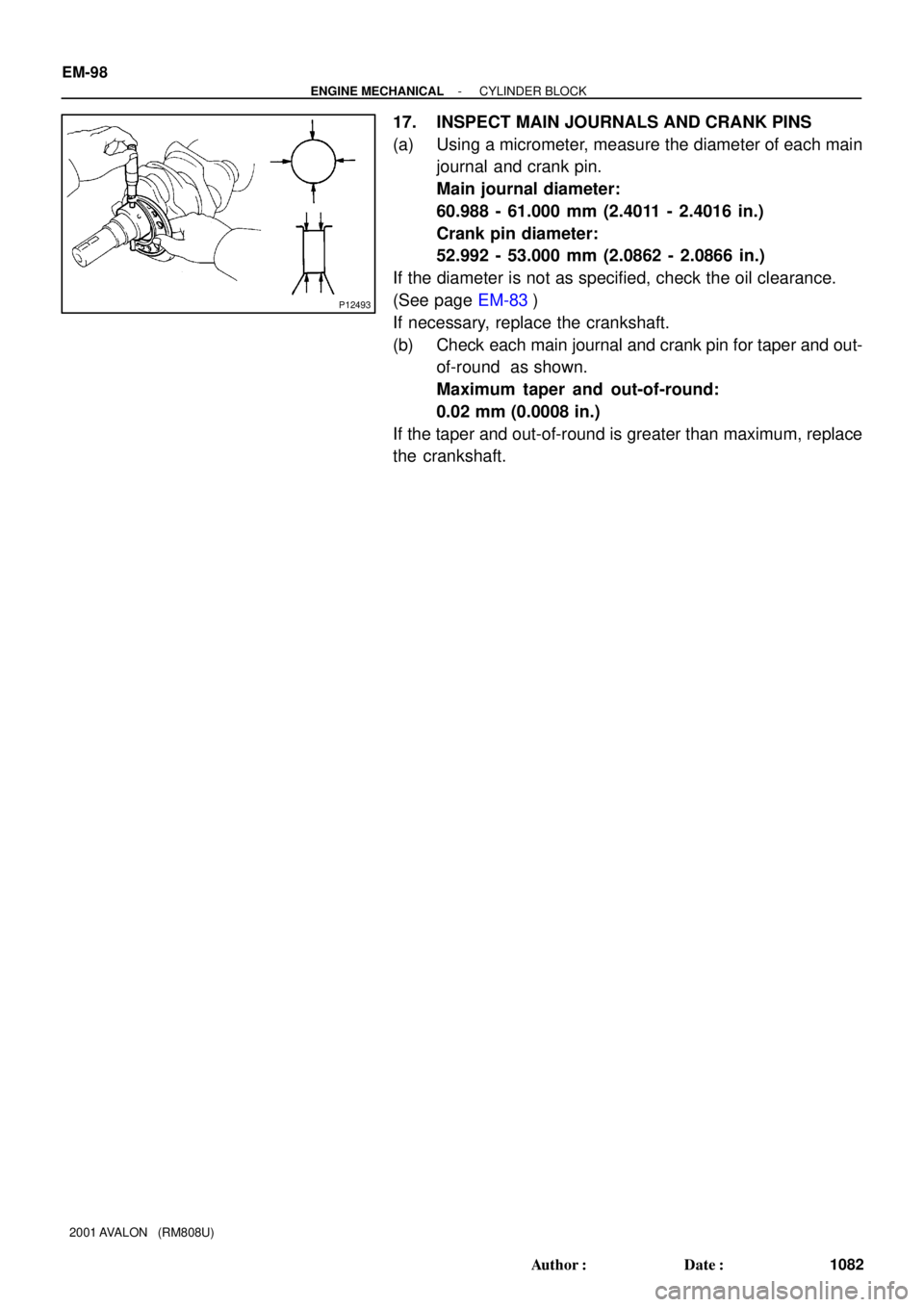
17. INSPECT MAIN JOURNALS AND CRANK PINS
(a) Using a micrometer, measure the diameter of each main
journal and crank pin.
Main journal diameter:
60.988 - 61.000 mm (2.4011 - 2.4016 in.)
Crank pin diameter:
52.992 - 53.000 mm (2.0862 - 2.0866 in.)
If the diameter is not as specified, check the oil clearance.
(See page EM-83)
If necessary, replace the crankshaft.
(b) Check each main journal and crank pin for taper and out-
of-round as shown.
Maximum taper and out-of-round:
0.02 mm (0.0008 in.)
If the taper and out-of-round is greater than maximum, replace
the crankshaft.