Page 3355 of 3833
TROUBLE DIAGNOSIS
ATC-79
C
D
E
F
G
H
I
K
L
MA
B
AT C
SYSTEM DESCRIPTION
Auto amplifier controls compressor operation by ambient temperature and signal from ECM.
Low Temperature Protection Control (With Gasoline Engine)
Auto amplifier will turn the compressor ON or OFF as determined by
a signal detected by ambient sensor.
When ambient temperatures are greater than -2°C, the compressor
turns ON. The compressor turns OFF when ambient temperatures
are less than -5°C.
Evaporator Freeze Protection Control (With Diesel Engine)
Auto amplifier will turn the compressor ON or OFF as determined by
a signal detected by intake sensor.
When intake temperatures are greater than 4°C, the compressor
turns ON. The compressor turns OFF when intake temperatures are
less than 2.5°C.
DIAGNOSTIC PROCEDURE
SYMPTOM: Magnet clutch does not engage when A/C switch is ON.
RHA094GB
RJIA0534E
RJIA0535E
Page 3360 of 3833
ATC-84
TROUBLE DIAGNOSIS
15. CHECK DUAL- PRESSURE SWITCH (YD ENGINE)
Refer to AT C - 8 5 , "
Dual-Pressure Switch (With Diesel Engine)" .
OK or NG
OK >> GO TO 16.
NG >> Replace the dual-pressure switch.
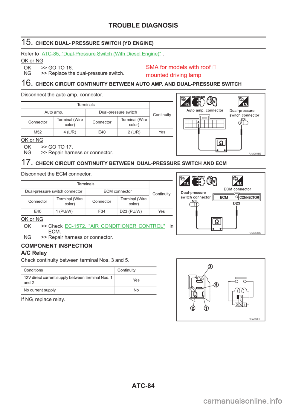
16. CHECK CIRCUIT CONTINUITY BETWEEN AUTO AMP. AND DUAL-PRESSURE SWITCH
Disconnect the auto amp. connector.
OK or NG
OK >> GO TO 17.
NG >> Repair harness or connector.
17. CHECK CIRCUIT CONTINUITY BETWEEN DUAL-PRESSURE SWITCH AND ECM
Disconnect the ECM connector.
OK or NG
OK >> Check EC-1572, "AIR CONDITIONER CONTROL" in
ECM.
NG >> Repair harness or connector.
COMPONENT INSPECTION
A/C Relay
Check continuity between terminal Nos. 3 and 5.
If NG, replace relay.
Terminals
Continuity Auto amp. Dual-pressure switch
ConnectorTerminal (Wire
color)ConnectorTerminal (Wire
color)
M52 4 (L/R) E40 2 (L/R) Yes
RJIA0545E
Terminals
Continuity Dual-pressure switch connector ECM connector
ConnectorTe r m i n a l ( W i r e
color)ConnectorTerminal (Wire
color)
E40 1 (PU/W) F34 D23 (PU/W) Yes
RJIA0546E
Conditions Continuity
12V direct current supply between terminal Nos. 1
and 2Ye s
No current supply No
RHA638H
SMA for models with roof �
mounted drivin
g lamp
Page 3363 of 3833
TROUBLE DIAGNOSIS
ATC-87
C
D
E
F
G
H
I
K
L
MA
B
AT C
*7ATC-78, "Magnet Clutch Circuit".*8AT C - 8 8 , "PERFORMANCE TEST
DIAGNOSES"
*9ATC-54, "Operational Check".
*10ATC-47, "
PROCEDURE", see No.5
to 7.*11 QR engine; EM-12, "Checking Drive
Belts" .
YD engine; EM-118, "
Checking Drive
Belts" .*12 QR25 engine; (WITH EURO-OBD)
EC-323, "
COOLING FAN CON-
TROL" .
QR25 engine; (WITHOOUT EUR-
OBD)EC-603, "
COOLING FAN
CONTROL" .
QR20 engine; (WITH EURO-OBD)
EC-1050, "
COOLING FAN CON-
TROL" .
QR20 engine; (WITHOUT EURO-
OBD)EC-1287, "
COOLING FAN
CONTROL" .
YD engine; EC-1508, "
SYSTEM
DESCRIPTION" .
Page 3425 of 3833
REFRIGERANT LINES
ATC-149
C
D
E
F
G
H
I
K
L
MA
B
AT C
NOTE:
After removing A/C manifold gauge set from service valves, wipe any residue from valves to prevent any
false readings by leak detector.
Cooling unit (Evaporator)
With engine OFF, turn blower fan on "High" for at least 15 seconds to dissipate any refrigerant trace in the
cooling unit. Wait a minimum of 10 minutes accumulation time (refer to the manufacturer's recommended
procedure for actual wait time) before inserting the leak detector probe into the drain hose.
Keep the probe inserted for at least 10 seconds. Use caution not to contaminate the probe tip with water
or dirt that may be in the drain hose.
5. If a leak detector detects a leak, verify at least once by blowing compressed air into area of suspected
leak, then repeat check as outlined above.
6. Do not stop when one leak is found. Continue to check for additional leaks at all system components.
If no leaks are found, perform steps 7 - 10.
7. Start engine.
8. Set the heater A/C control as follows;
a. A/C switch: ON
b. Face mode
c. Intake position: Recirculation
d. Max cold temperature
e. Fan speed: High
9. Run engine at 1,500 rpm for at least 2 minutes.
10. Turn engine off and perform leak check again following steps 4 through 6 above.
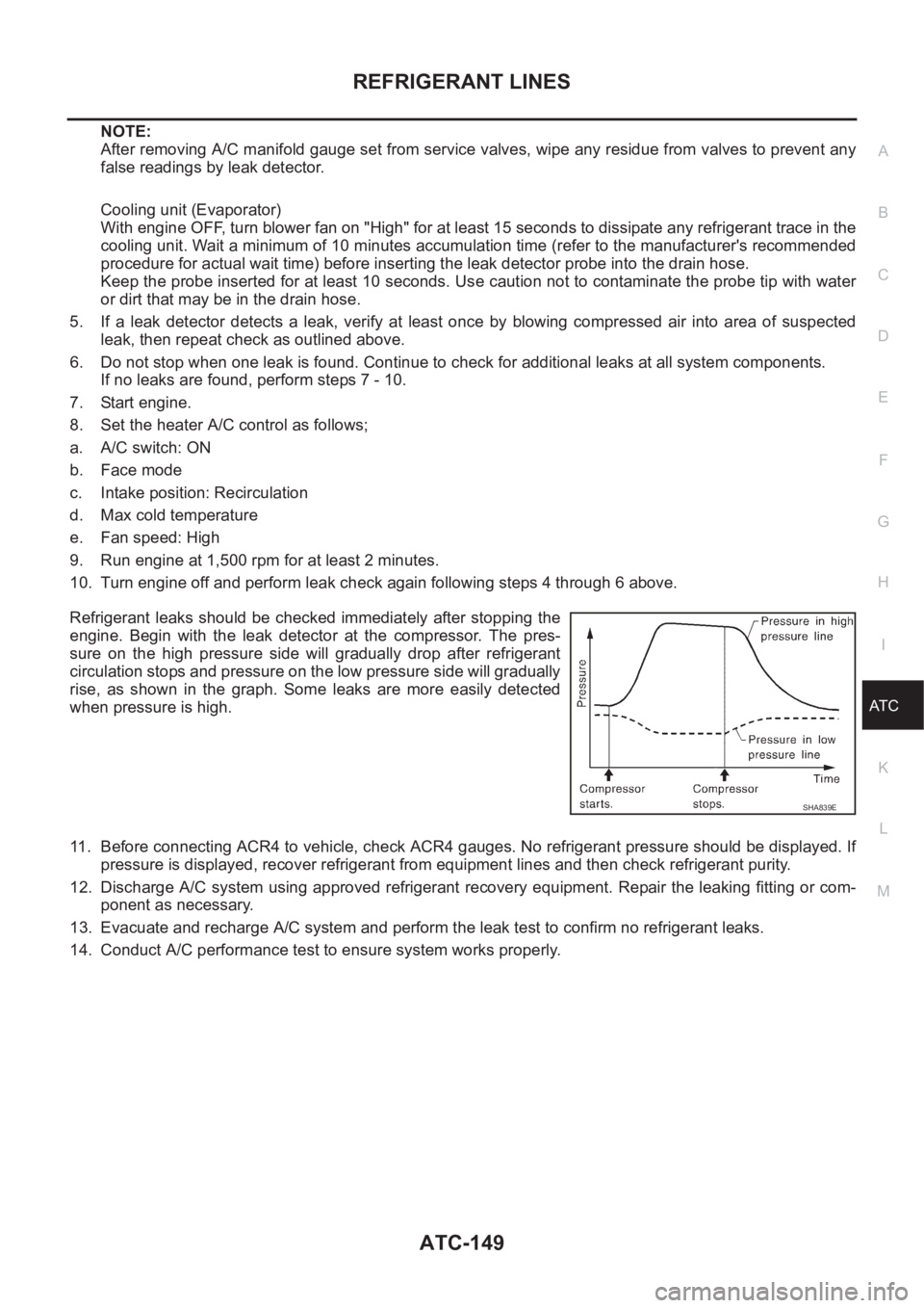
Refrigerant leaks should be checked immediately after stopping the
engine. Begin with the leak detector at the compressor. The pres-
sure on the high pressure side will gradually drop after refrigerant
circulation stops and pressure on the low pressure side will gradually
rise, as shown in the graph. Some leaks are more easily detected
when pressure is high.
11. Before connecting ACR4 to vehicle, check ACR4 gauges. No refrigerant pressure should be displayed. If
pressure is displayed, recover refrigerant from equipment lines and then check refrigerant purity.
12. Discharge A/C system using approved refrigerant recovery equipment. Repair the leaking fitting or com-
ponent as necessary.
13. Evacuate and recharge A/C system and perform the leak test to confirm no refrigerant leaks.
14. Conduct A/C performance test to ensure system works properly.
SHA839E
Page 3426 of 3833
ATC-150
SERVICE DATA AND SPECIFICATIONS (SDS)
SERVICE DATA AND SPECIFICATIONS (SDS)
PFP:00030
COMPRESSOREJS00281
LUBRICANTEJS00282
REFRIGERANTEJS00283
ENGINE IDLING SPEEDEJS00284
Refer to EC-38, "IDLE SPEED" for QR25 engine (WITH EURO-OBD), EC-448, "IDLE SPEED" for QR25
engine (WITHOUT EURO-OBD), EC-771, "
IDLE SPEED" for QR20 engine (WITH EURO-OBD), EC-1135,
"IDLE SPEED" for QR20 engine (WITHOUT EURO-OBD), EC-1412, "Basic Inspection" ,see No.3 for YD
engine.
BELT TENSIONEJS00285
Refer to EM-12, "DRIVE BELTS" for QR engine,EM-118, "DRIVE BELTS" for YD engine.
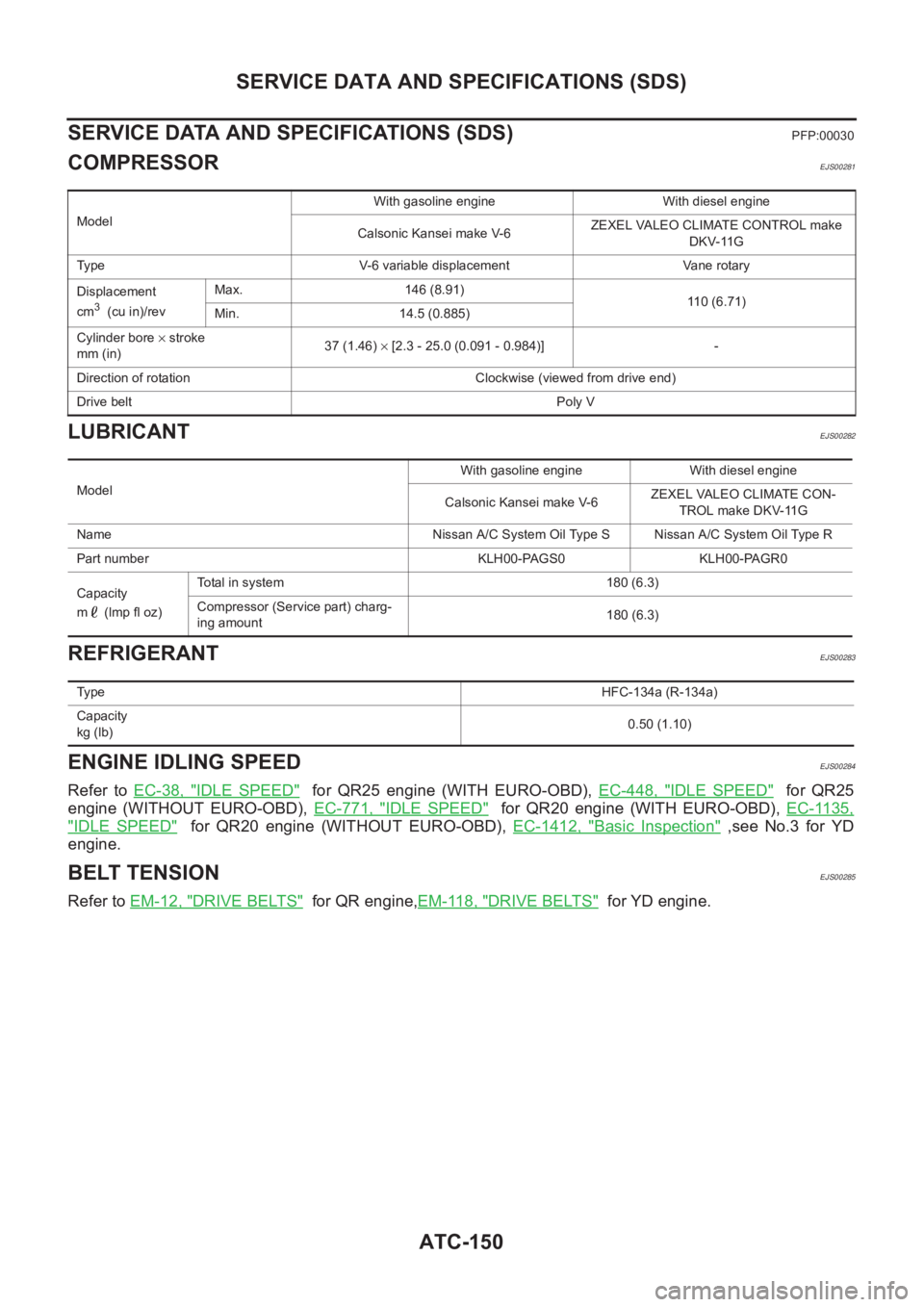
ModelWith gasoline engine With diesel engine
Calsonic Kansei make V-6ZEXEL VALEO CLIMATE CONTROL make
DKV-11G
Type V-6 variable displacement Vane rotary
Displacement
cm
3 (cu in)/revMax. 146 (8.91)
110 (6.71)
Min. 14.5 (0.885)
Cylinder bore × stroke
mm (in)37 (1.46) × [2.3 - 25.0 (0.091 - 0.984)] -
Direction of rotation Clockwise (viewed from drive end)
Drive beltPoly V
ModelWith gasoline engine With diesel engine
Calsonic Kansei make V-6ZEXEL VALEO CLIMATE CON-
TROL make DKV-11G
Name Nissan A/C System Oil Type S Nissan A/C System Oil Type R
Part number KLH00-PAGS0 KLH00-PAGR0
Capacity
m (lmp fl oz)Total in system 180 (6.3)
Compressor (Service part) charg-
ing amount180 (6.3)
Ty p eHFC-134a (R-134a)
Capacity
kg (lb)0.50 (1.10)
Page 3433 of 3833
TROUBLE DIAGNOSIS
MTC-7
C
D
E
F
G
H
I
K
L
MA
B
MTC
Operational CheckEJS001FE
The purpose of the operational check is to confirm that the system operates properly.
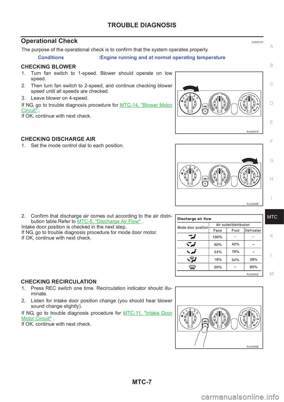
CHECKING BLOWER
1. Turn fan switch to 1-speed. Blower should operate on low
speed.
2. Then turn fan switch to 2-speed, and continue checking blower
speed until all speeds are checked.
3. Leave blower on 4-speed.
If NG, go to trouble diagnosis procedure for MTC-14, "
Blower Motor
Circuit" .
If OK, continue with next check.
CHECKING DISCHARGE AIR
1. Set the mode control dial to each position.
2. Confirm that discharge air comes out according to the air distri-
bution table.Refer to MTC-5, "
Discharge Air Flow" .
Intake door position is checked in the next step.
If NG, go to trouble diagnosis procedure for mode door motor.
If OK, continue with next check.
CHECKING RECIRCULATION
1. Press REC switch one time. Recirculation indicator should illu-
minate.
2. Listen for intake door position change (you should hear blower
sound change slightly).
If NG, go to trouble diagnosis procedure for MTC-11, "
Intake Door
Motor Circuit" .
If OK, continue with next check.Conditions :Engine running and at normal operating temperature
RJIA0587E
RJIA0588E
RJIA0492E
RJIA0589E
Page 3468 of 3833
SC-12
CHARGING SYSTEM
CHARGING SYSTEM
PFP:00011
System Description EKS00316
The alternator provides DC voltage to operate the vehicle's electrical system and to keep the battery charged.
The voltage output is controlled by the IC regulator.
Power is supplied at all times
●to alternator terminal 4 (S)
●through 10A fuse (No.34, located in the fuse and fusible link box)
●to alternator terminal B
●through 120A (Gasoline engine models) or 100A (Diesel engine models) fusible link (letter A, located in
the fuse and fusible link box).
Terminal B supplies power to charge the battery and operate the vehicle's electrical system. Output voltage is
controlled by the IC regulator at terminal 4 (S) detecting the input voltage. The charging circuit is protected by
the 120A (Gasoline engine models) or 100A (Diesel engine models) link.
The alternator is grounded to the engine block.
With the ignition switch in the ON or START position, power is supplied
●through 10A fuse [No. 11, located in the fuse block (J/B)]
●to combination meter terminal 46 (LHD models) or terminal 59 (RHD models) for the charge warning
lamp.
Ground is supplied with power and ground supplied
●to terminal 64 (LHD models) or terminal 54 ( RHD models) of the combination meter
●through terminal 3 (L) of the alternator
●to terminal E of the alternator
●through body ground E30.
The charge warning lamp will illuminate. When the alternator is providing sufficient voltage with the engine
running, the ground is opened and the charge warning lamp will go off.
If the charge warning lamp illuminates with the engine running, a malfunction is indicated.
Page 3499 of 3833
HEADLAMP - DAYTIME LIGHT SYSTEM -
LT-9
C
D
E
F
G
H
I
J
L
MA
B
LT
HEADLAMP - DAYTIME LIGHT SYSTEM -PFP:26010
System DescriptionEKS003BB
DESCRIPTION
The headlamp system on vehicles for North Europe contains a daytime light control unit. The unit activates the
following whenever the engine is running with the lighting switch in the OFF position:
●Low beam headlamps
●Parking, license, tail and illumination lamps
Power is supplied at all times
●through 10A fuse (No. 31, located in the fuse and fusible link box)
●to daytime light control unit terminal 1 and
●to lighting switch terminal 11.
Power is also supplied at all times
●through 15A fuse (No. 41, located in the fuse and fusible link box)
●to daytime light control unit terminal 3 and
●to lighting switch terminal 5.
Power is also supplied at all times
●through 15A fuse (No. 40, located in the fuse and fusible link box)
●to daytime light control unit terminal 2 and
●to lighting switch terminal 8.
With the ignition switch in the ON or START position, power is supplied
●through 10A fuse [No. 13, located in the fuse block (J/B)]
●to daytime light control unit terminal 7.
With the ignition switch in the START position, power is supplied
●through 10A fuse [No. 7, located in the fuse block (J/B)]
●to daytime light control unit terminal 6.
HEADLAMP OPERATION (DAYTIME LIGHT CANCEL OPERATION)
When the lighting switch is turned to the 1st or 2nd position, power is supplied
●through lighting switch terminal 12,
●to daytime light control unit terminal 11.
Then daytime light will be canceled. And the lighting system operation will be the same as no daytime light
system.
DAYTIME LIGHT OPERATION
With the engine running and the lighting switch in the OFF position, power is supplied
●from alternator terminal 3
●to daytime light control unit terminal 8,
●through daytime light control unit terminal 5
●to terminal 3 of headlamp LH,
●through daytime light control unit terminal 4
●to terminal 3 of headlamp RH and
●through daytime light control unit terminal 10
●to tail lamp and illumination.
Ground is supplied to terminal 2 of each headlamp through body grounds E24 and E50.
SMA for models with roof mounted driving lamp