2001 NISSAN X-TRAIL engine control
[x] Cancel search: engine controlPage 3000 of 3833
SB-18
SEAT BELT WARNING SYSTEM
Vehicle Speed Signal Inspection
EHS000GZ
1. COMBINATION METER CHECK
Check the speed meter in combination meter operates normally.
OK or NG
OK >> GO TO 2.
NG >> Check combination meter system. Refer to DI-12, "
SYMPTOM CHART" (LHD models) or DI-32,
"SYMPTOM CHART" (RHD models).
2. VEHICLE SPEED INPUT SIGNAL INSPECTION
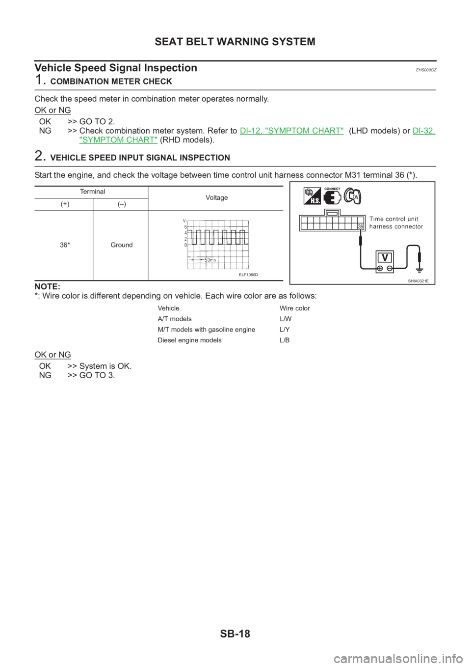
Start the engine, and check the voltage between time control unit harness connector M31 terminal 36 (*).
NOTE:
*: Wire color is different depending on vehicle. Each wire color are as follows:
OK or NG
OK >> System is OK.
NG >> GO TO 3.
Terminal
Vo l ta g e
(+) (–)
36* Ground
Vehicle Wire color
A/T models L/W
M/T models with gasoline engine L/Y
Diesel engine models L/B
SHIA0321EELF1080D
Page 3001 of 3833
SEAT BELT WARNING SYSTEM
SB-19
C
D
E
F
G
I
J
K
L
MA
B
SB
3.HARNESS CONTINUITY INSPECTION
1. Turn ignition switch “OFF”.
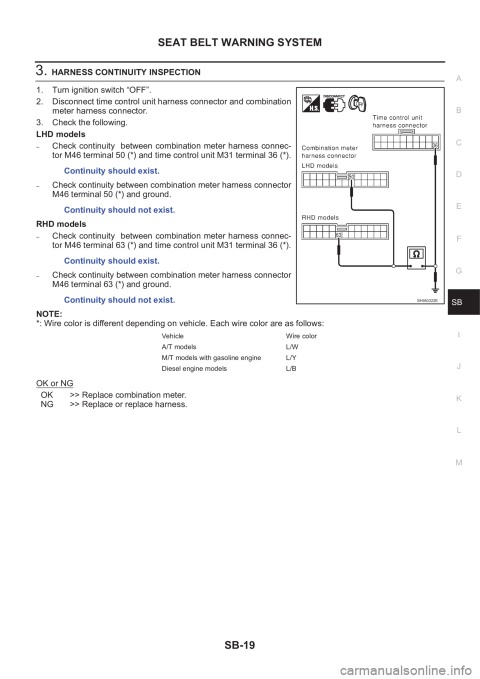
2. Disconnect time control unit harness connector and combination
meter harness connector.
3. Check the following.
LHD models
–Check continuity between combination meter harness connec-
tor M46 terminal 50 (*) and time control unit M31 terminal 36 (*).
–Check continuity between combination meter harness connector
M46 terminal 50 (*) and ground.
RHD models
–Check continuity between combination meter harness connec-
tor M46 terminal 63 (*) and time control unit M31 terminal 36 (*).
–Check continuity between combination meter harness connector
M46 terminal 63 (*) and ground.
NOTE:
*: Wire color is different depending on vehicle. Each wire color are as follows:
OK or NG
OK >> Replace combination meter.
NG >> Replace or replace harness.Continuity should exist.
Continuity should not exist.
Continuity should exist.
Continuity should not exist.
Vehicle Wire color
A/T models L/W
M/T models with gasoline engine L/Y
Diesel engine models L/B
SHIA0322E
Page 3054 of 3833
BL-2
Power Supply and Ground Circuit Check ............... 60
Time Control Unit Lock Signal Circuit Check .......... 61
Time Control Unit Unlock Signal Circuit Check ...... 62
Hazard Reminder Check ........................................ 62
ID Code Entry Procedure ....................................... 63
Remote Controller Battery Replacement ................ 64
FRONT DOOR LOCK ............................................... 65
Component Parts Location ..................................... 65
Inspection and Adjustment ..................................... 65
OUT SIDE HANDLE ROD ADJUSTMENT .......... 65
Removal and Installation ........................................ 65
REMOVAL ........................................................... 65
INSTALLATION .................................................... 66
Disassembly and Assembly .................................... 67
DISASSEMBLY ................................................... 67
ASSEMBLY ......................................................... 67
REAR DOOR LOCK .................................................. 68
Component Parts Location ..................................... 68
Inspection and Adjustment ..................................... 68
OUT SIDE HANDLE ROD ADJUSTMENT .......... 68
Removal and Installation ........................................ 68
REMOVAL ........................................................... 68
INSTALLATION .................................................... 69
Disassembly and Assembly .................................... 70
DISASSEMBLY ................................................... 70
ASSEMBLY ......................................................... 70
BACK DOOR ............................................................. 71
Fitting Adjustment ................................................... 71
VERTICAL/LATERAL CLEARANCE ADJUST-
MENT .................................................................. 71
Back Door Assembly .............................................. 72
REMOVAL AND INSTALLATION ......................... 72
INSPECTION ....................................................... 72
Removal and Installation of Back Door Handle ...... 72
Removal and Installation of Back Door Lock and Actuator ................................................................... 73
Removal and Installation of Back Door Weatherstrip ... 73
FUEL FILLER LID OPENER ..................................... 75
Component Parts Location ..................................... 75
THEFT WARNING SYSTEM ..................................... 76
Wiring Diagram — THEFT —/PRI-WIRE ................ 76
LHD MODELS ...................................................... 76
RHD MODELS ..................................................... 78
NATS (NISSAN ANTI-THEFT SYSTEM) ................... 80
Component Parts and Harness Connector Location ... 80
System Description ................................................. 81
System Composition ............................................... 82
Wiring Diagram — NATS — .................................... 83
GASOLINE ENGINE MODELS ............................ 83
DIESEL ENGINE MODELS ................................. 84
CONSULT-II ............................................................ 85
CONSULT-II INSPECTION PROCEDURE .......... 85
CONSULT-II DIAGNOSTIC TEST MODE FUNC-
TION .................................................................... 85
HOW TO READ SELF-DIAGNOSTIC RESULTS ... 86
NATS SELF-DIAGNOSTIC RESULTS ITEM
CHART ................................................................. 86
Work Flow ............................................................... 88
Trouble Diagnoses .................................................. 89
SYMPTOM MATRIX CHART 1 ............................ 89
SYMPTOM MATRIX CHART 2 ............................ 90
DIAGNOSTIC SYSTEM DIAGRAM ..................... 90
Diagnostic Procedure 1 ........................................... 91
Diagnostic Procedure 2 ........................................... 91
Diagnostic Procedure 3 ........................................... 94
Diagnostic Procedure 4 ........................................... 95
Diagnostic Procedure 5 ........................................... 96
Diagnostic Procedure 6 ........................................... 97
Diagnostic Procedure 7 ........................................... 98
Diagnostic Procedure 8 ........................................... 99
How to Replace NATS IMMU ................................100
Page 3134 of 3833
BL-82
NATS (NISSAN ANTI-THEFT SYSTEM)
System Composition
EIS001RS
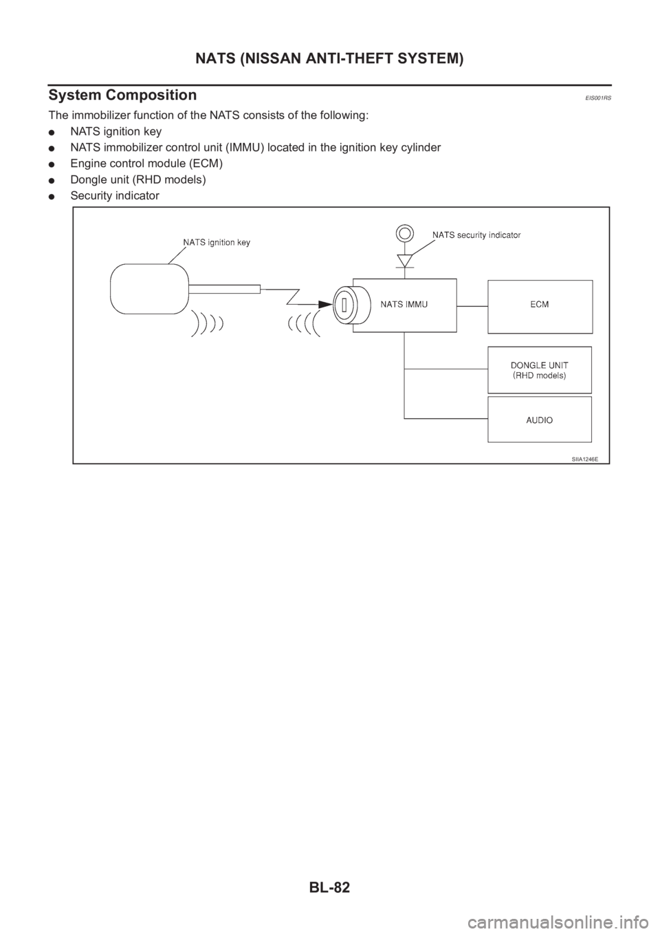
The immobilizer function of the NATS consists of the following:
●NATS ignition key
●NATS immobilizer control unit (IMMU) located in the ignition key cylinder
●Engine control module (ECM)
●Dongle unit (RHD models)
●Security indicator
SIIA1246E
Page 3277 of 3833
ATC-1
AUTOMATIC AIR CONDITIONER
J AIR CONDITIONER
CONTENTS
C
D
E
F
G
H
I
K
L
M
SECTION
A
B
AT C
AUTOMATIC AIR CONDITIONER
PRECAUTIONS .......................................................... 4
Precautions for Supplemental Restraint System
(SRS) “AIR BAG” and “SEAT BELT PRE-TEN-
SIONER” .................................................................. 4
Precautions for Working with HFC-134a (R-134a) ..... 4
General Refrigerant Precautions .............................. 5
Lubricant Precautions .............................................. 5
Precautions for Refrigerant Connection ................... 5
FEATURES OF NEW TYPE REFRIGERANT
CONNECTION ...................................................... 6
O-RING AND REFRIGERANT CONNECTION ..... 7
Precautions for Servicing Compressor ..................... 9
Precautions for Service Equipment ........................ 10
RECOVERY/RECYCLING EQUIPMENT ............ 10
ELECTRONIC LEAK DETECTOR ...................... 10
VACUUM PUMP ................................................. 10
MANIFOLD GAUGE SET .................................... 10
SERVICE HOSES ................................................ 11
SERVICE COUPLERS ......................................... 11
REFRIGERANT WEIGHT SCALE ....................... 11
CALIBRATING ACR4 WEIGHT SCALE ............... 11
CHARGING CYLINDER ...................................... 12
Precautions for Leak Detection Dye ....................... 12
IDENTIFICATION ................................................ 12
IDENTIFICATION LABEL FOR VEHICLE ........... 13
Wiring Diagrams and Trouble Diagnosis ................ 13
PREPARATION ......................................................... 14
Special Service Tools ............................................. 14
WITH GASOLINE ENGINE (CWV-615M COM-
PRESSOR) ......................................................... 14
WITH DIESEL ENGINE (DKV-11G COMPRES-
SOR) ................................................................... 14
HFC-134a (R-134a) Service Tools and Equipment ... 15
REFRIGERATION SYSTEM ..................................... 18
Refrigerant Cycle ................................................... 18
REFRIGERANT FLOW ....................................... 18
FREEZE PROTECTION (WITH GASOLINE
ENGINE: CWV-615M COMPRESSOR) .............. 18
Refrigerant System Protection ............................... 18
REFRIGERANT PRESSURE SENSOR (WITH GASOLINE ENGINE: CWV-615M COMPRES-
SOR) ................................................................... 18
DUAL-PRESSURE SWITCH (WITH DIESEL
ENGINE: DKV-11G COMPRESSOR) .................. 18
PRESSURE RELIEF VALVE (WITH GASOLINE
ENGINE: CWV-615M COMPRESSOR) .............. 18
V-6 Variable Displacement Compressor (With Gas-
oline Engine: CWV-615M Compressor) .................. 19
GENERAL INFORMATION ................................. 19
DESCRIPTION .................................................... 20
Component Layout ................................................. 23
LUBRICANT .............................................................. 24
Maintenance of Lubricant Quantity in Compressor ... 24
LUBRICANT ........................................................ 24
LUBRICANT RETURN OPERATION .................. 24
LUBRICANT ADJUSTING PROCEDURE FOR
COMPONENTS REPLACEMENT EXCEPT
COMPRESSOR .................................................. 25
LUBRICANT ADJUSTING PROCEDURE FOR
COMPRESSOR REPLACEMENT ....................... 25
AIR CONDITIONER CONTROL ............................... 27
Overview Air Conditioner LAN Control System ...... 27
System Construction .............................................. 27
OPERATION ........................................................ 27
TRANSMISSION DATA AND TRANSMISSION
ORDER ............................................................... 28
AIR MIX DOOR CONTROL (AUTOMATIC TEM-
PERATURE CONTROL) ..................................... 28
FAN SPEED CONTROL ...................................... 29
INTAKE DOOR CONTROL ................................. 29
OUTLET DOOR CONTROL ................................ 29
MAGNET CLUTCH CONTROL ........................... 29
SELF-DIAGNOSTIC SYSTEM ............................ 29
Overview of Control system .................................... 29
Control Operation ................................................... 30
DISPLAY SCREEN .............................................. 30
AUTO SWITCH ................................................... 30
TEMPERATURE DIAL (POTENTIO TEMPERA-
TURE CONTROL) ............................................... 30
A/C SWITCH ....................................................... 30
Page 3278 of 3833
ATC-2
DEFROSTER (DEF) SWITCH ............................. 30
MODE SWITCH ................................................... 30
FAN SWITCH ...................................................... 30
OFF SWITCH ...................................................... 30
FRESH (FRE) SWITCH ....................................... 30
RECIRCULATION (REC) SWITCH ..................... 30
Discharge Air Flow ................................................. 31
System Description ................................................. 32
SWITCHES AND THEIR CONTROL FUNCTION ... 32
TROUBLE DIAGNOSIS ............................................ 33
How to Perform Trouble Diagnoses for Quick and
Accurate Repair ...................................................... 33
WORK FLOW ...................................................... 33
SYMPTOM TABLE .............................................. 33
Component Parts and Harness Connector Location ... 34
ENGINE COMPARTMENT .................................. 34
PASSENGER COMPARTMENT .......................... 35
Circuit Diagram ....................................................... 36
WITH GASOLINE ENGINE ................................. 36
WITH DIESEL ENGINE ....................................... 37
Wiring Diagram ....................................................... 38
WITH GASOLINE ENGINE ................................. 38
WITH DIESEL ENGINE ....................................... 41
Auto Amp. Terminals and Reference Value ............ 44
PIN CONNECTOR TERMINAL LAYOUT ............ 44
AUTO AMP. INSPECTION TABLE ...................... 44
Self-diagnosis Function .......................................... 46
DESCRIPTION .................................................... 46
PROCEDURE ...................................................... 47
AUXILIARY MECHANISM: TEMPERATURE
SETTING TRIMMER ........................................... 52
AUXILIARY MECHANISM: FOOT POSITION
SETTING TRIMMER ........................................... 53
AUXILIARY MECHANISM: INLET PORT MEM-
ORY FUNCTION (FOR LHD MODELS) .............. 54
Operational Check .................................................. 54
CHECKING MEMORY FUNCTION ..................... 54
CHECKING BLOWER ......................................... 55
CHECKING DISCHARGE AIR ............................ 55
CHECKING RECIRCULATION ............................ 55
CHECKING TEMPERATURE DECREASE ......... 56
CHECKING TEMPERATURE INCREASE .......... 56
CHECKING AUTO MODE ................................... 56
Power Supply and Ground Circuit for Auto Amp. ... 57
INSPECTION FLOW ........................................... 57
COMPONENT DESCRIPTION ............................ 57
DIAGNOSTIC PROCEDURE .............................. 58
LAN System Circuit ............................................. ... 59
DIAGNOSTIC PROCEDURE .............................. 59
Mode Door Motor Circuit ........................................ 62
INSPECTION FLOW ........................................
... 62
SYSTEM DESCRIPTION .................................... 63
COMPONENT DESCRIPTION ............................ 64
DIAGNOSTIC PROCEDURE .............................. 64
Air Mix Door Motor Circuit ...................................... 64
INSPECTION FLOW ........................................... 65
SYSTEM DESCRIPTION .................................... 66
COMPONENT DESCRIPTION ............................ 66
DIAGNOSTIC PROCEDURE .............................. 67Intake Door Motor Circuit ........................................ 68
INSPECTION FLOW ............................................ 68
SYSTEM DESCRIPTION ..................................... 69
COMPONENT DESCRIPTION ............................ 69
DIAGNOSTIC PROCEDURE ............................... 70
Blower Motor Circuit ................................................ 70
INSPECTION FLOW ............................................ 71
SYSTEM DESCRIPTION ..................................... 72
COMPONENT DESCRIPTION ............................ 74
DIAGNOSTIC PROCEDURE ............................... 74
COMPONENT INSPECTION ............................... 77
Magnet Clutch Circuit .............................................. 78
INSPECTION FLOW ............................................ 78
SYSTEM DESCRIPTION ..................................... 79
DIAGNOSTIC PROCEDURE ............................... 79
COMPONENT INSPECTION ............................... 84
Insufficient Cooling .................................................. 86
INSPECTION FLOW ............................................ 86
PERFORMANCE TEST DIAGNOSES ................ 88
PERFORMANCE CHART .................................... 90
TROUBLE DIAGNOSES FOR UNUSUAL PRES-
SURE ................................................................... 92
Insufficient Heating ................................................. 95
INSPECTION FLOW ............................................ 95
Noise ....................................................................... 97
INSPECTION FLOW ............................................ 97
Self-diagnosis ......................................................... 98
INSPECTION FLOW ............................................ 98
Memory Function .................................................... 99
INSPECTION FLOW ............................................ 99
Ambient Sensor Circuit .........................................100
COMPONENT DESCRIPTION ..........................100
AMBIENT TEMPERATURE INPUT PROCESS .100
DIAGNOSTIC PROCEDURE .............................100
COMPONENT INSPECTION .............................102
In-vehicle Sensor Circuit .......................................102
COMPONENT DESCRIPTION ..........................102
DIAGNOSTIC PROCEDURE .............................103
COMPONENT INSPECTION .............................104
Sunload Sensor Circuit .........................................105
COMPONENT DESCRIPTION ..........................105
SUNLOAD INPUT PROCESS ...........................105
DIAGNOSTIC PROCEDURE .............................105
COMPONENT INSPECTION .............................107
Intake Sensor Circuit .............................................108
COMPONENT DESCRIPTION ..........................108
DIAGNOSTIC PROCEDURE .............................108
CONTROLLER ........................................................ 111
Removal and Installation .......................................111
Disassembly and Assembly ..................................111
AMBIENT SENSOR ................................................112
Removal and Installation .......................................112
IN-VEHICLE SENSOR ............................................113
Removal and Installation .......................................113
SUNLOAD SENSOR ...............................................114
Removal and Installation .......................................114
INTAKE SENSOR CIRCUIT ....................................115
Removal and Installation .......................................115
BLOWER UNIT ........................................................116
Page 3279 of 3833
ATC-3
C
D
E
F
G
H
I
K
L
MA
B
AT C Removal and Installation ....................................... 116
REMOVAL .......................................................... 116
INSTALLATION .................................................. 116
Disassembly and Assembly .................................. 117
BLOWER MOTOR ...................................................118
Removal and Installation ....................................... 118
INTAKE DOOR MOTOR ..........................................119
Removal and Installation ....................................... 119
FAN CONTROL AMPLIFIER .................................. 120
Removal and Installation ...................................... 120
VENTILATION AIR FILTER .................................... 121
Removal and Installation ...................................... 121
FUNCTION ........................................................ 121
REPLACEMENT TIMING .................................. 121
REPLACEMENT AND PROCEDURES ............ 121
CLEANING ....................................................... . 121
HEATER & COOLING UNIT ASSEMBLY .............. 122
Removal and Installation ...................................... 122
REMOVAL ......................................................... 122
INSTALLATION ................................................. 123
Disassembly and Assembly ................................. 123
MODE DOOR MOTOR ........................................... 124
Removal and Installation ...................................... 124
AIR MIX DOOR MOTOR ......................................... 125
Removal and Installation ...................................... 125
HEATER CORE ...................................................... 126
Removal and Installation ...................................... 126
DUCTS AND GRILLES .......................................... 127
Removal and Installation ...................................... 127
VENTILATOR DUCT, DEFROSTER NOZZLE
AND DEFROSTER DUCTS .............................. 127
CENTER VENTILATOR GRILLE ...................... 127
SIDE VENTILATOR GRILLE ............................. 127
FOOT DUCT ..................................................... 128
FLOOR DUCT ................................................... 128
REFRIGERANT LINES ........................................... 129
HFC-134a (R-134a) Service Procedure ............... 129
SETTING OF SERVICE TOOLS AND EQUIP-
MENT ................................................................ 129
Components ......................................................... 131
WITH GASOLINE ENGINE ............................... 131
WITH DIESEL ENGINE .................................... 132
Removal and Installation for Compressor ............ 132REMOVAL .........................................................132
INSTALLATION .................................................134
Removal and Installation for Compressor Clutch . 135
REMOVAL .........................................................135
INSTALLATION .................................................138
Removal and Installation for Low-pressure flexible
hose ......................................................................141
REMOVAL .........................................................141
INSTALLATION .................................................141
Removal and Installation for High-pressure flexible
hose ......................................................................142
REMOVAL .........................................................142
INSTALLATION .................................................142
Removal and Installation for High-pressure pipe ..142
REMOVAL .........................................................142
INSTALLATION .................................................142
Removal and Installation for Refrigerant Pressure
Sensor ..................................................................143
Removal and Installation for Dual-pressure Switch .143
Removal and Installation for Condenser ..............143
REMOVAL .........................................................143
INSTALLATION .................................................144
Removal and Installation for Evaporator ..............145
REMOVAL .........................................................145
INSTALLATION .................................................145
Removal and Installation for Expansion Valve ......146
Removal and Installation for Liquid Tank ..............146
REMOVAL .........................................................146
INSTALLATION .................................................146
Checking for Refrigerant Leaks ............................146
Checking System for Leaks Using the Fluorescent
Leak Detector .......................................................147
Dye Injection .........................................................147
Electronic Refrigerant Leak Detector ....................147
PRECAUTIONS FOR HANDLING LEAK
DETECTOR .......................................................147
CHECKING PROCEDURE ...............................148
SERVICE DATA AND SPECIFICATIONS (SDS) ....150
COMPRESSOR ....................................................150
LUBRICANT .........................................................150
REFRIGERANT ....................................................150
ENGINE IDLING SPEED ......................................150
BELT TENSION ................................................... .150
Page 3294 of 3833
ATC-18
REFRIGERATION SYSTEM
REFRIGERATION SYSTEM
PFP:KA990
Refrigerant CycleEJS000TD
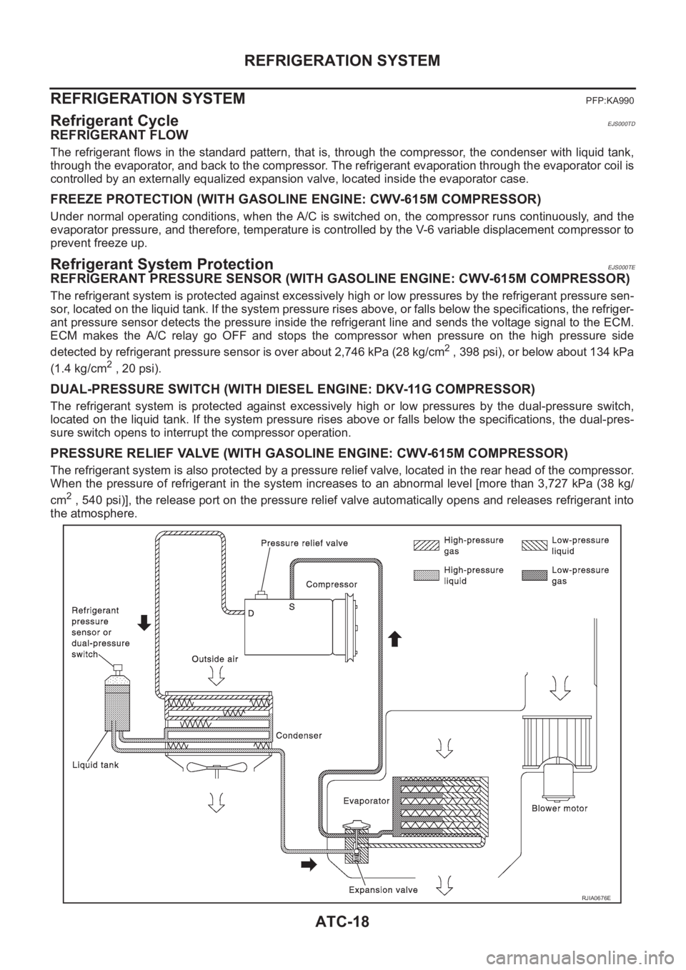
REFRIGERANT FLOW
The refrigerant flows in the standard pattern, that is, through the compressor, the condenser with liquid tank,
through the evaporator, and back to the compressor. The refrigerant evaporation through the evaporator coil is
controlled by an externally equalized expansion valve, located inside the evaporator case.
FREEZE PROTECTION (WITH GASOLINE ENGINE: CWV-615M COMPRESSOR)
Under normal operating conditions, when the A/C is switched on, the compressor runs continuously, and the
evaporator pressure, and therefore, temperature is controlled by the V-6 variable displacement compressor to
prevent freeze up.
Refrigerant System ProtectionEJS000TE
REFRIGERANT PRESSURE SENSOR (WITH GASOLINE ENGINE: CWV-615M COMPRESSOR)
The refrigerant system is protected against excessively high or low pressures by the refrigerant pressure sen-
sor, located on the liquid tank. If the system pressure rises above, or falls below the specifications, the refriger-
ant pressure sensor detects the pressure inside the refrigerant line and sends the voltage signal to the ECM.
ECM makes the A/C relay go OFF and stops the compressor when pressure on the high pressure side
detected by refrigerant pressure sensor is over about 2,746 kPa (28 kg/cm
2 , 398 psi), or below about 134 kPa
(1.4 kg/cm
2 , 20 psi).
DUAL-PRESSURE SWITCH (WITH DIESEL ENGINE: DKV-11G COMPRESSOR)
The refrigerant system is protected against excessively high or low pressures by the dual-pressure switch,
located on the liquid tank. If the system pressure rises above or falls below the specifications, the dual-pres-
sure switch opens to interrupt the compressor operation.
PRESSURE RELIEF VALVE (WITH GASOLINE ENGINE: CWV-615M COMPRESSOR)
The refrigerant system is also protected by a pressure relief valve, located in the rear head of the compressor.
When the pressure of refrigerant in the system increases to an abnormal level [more than 3,727 kPa (38 kg/
cm
2 , 540 psi)], the release port on the pressure relief valve automatically opens and releases refrigerant into
the atmosphere.
RJIA0676E