Page 3590 of 3833

DI-32
COMBINATION METERS (RHD MODELS)
SYMPTOM CHART
Power Supply and Ground Circuit CheckEKS0030O
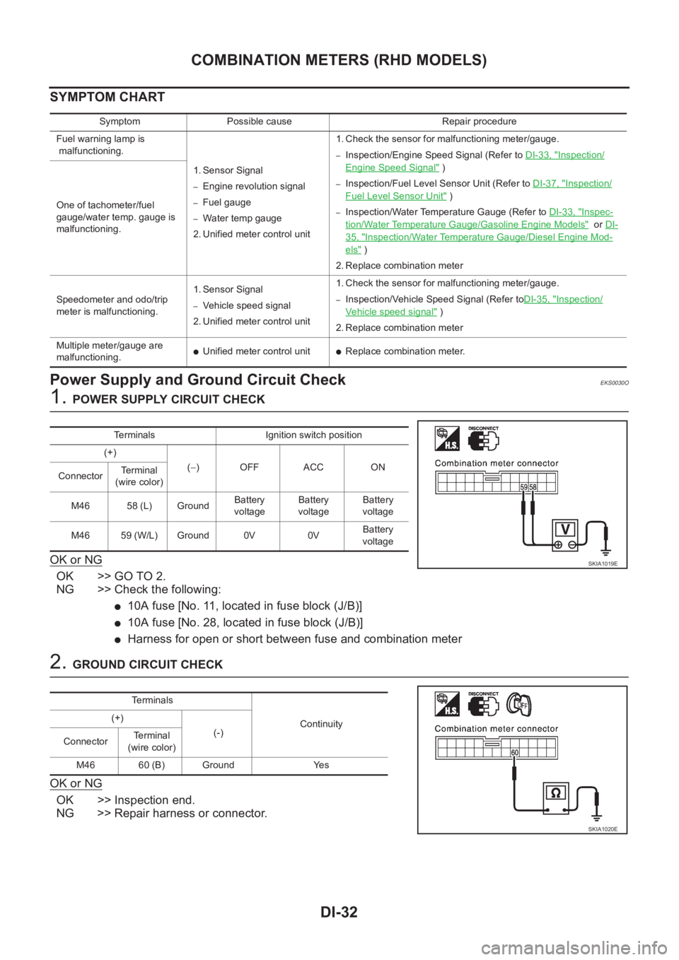
1. POWER SUPPLY CIRCUIT CHECK
OK or NG
OK >> GO TO 2.
NG >> Check the following:
●10A fuse [No. 11, located in fuse block (J/B)]
●10A fuse [No. 28, located in fuse block (J/B)]
●Harness for open or short between fuse and combination meter
2. GROUND CIRCUIT CHECK
OK or NG
OK >> Inspection end.
NG >> Repair harness or connector.
Symptom Possible cause Repair procedure
Fuel warning lamp is
malfunctioning.
1. Sensor Signal
–Engine revolution signal
–Fuel gauge
–Water temp gauge
2. Unified meter control unit 1. Check the sensor for malfunctioning meter/gauge.
–Inspection/Engine Speed Signal (Refer to DI-33, "Inspection/
Engine Speed Signal" )
–Inspection/Fuel Level Sensor Unit (Refer to DI-37, "Inspection/
Fuel Level Sensor Unit" )
–Inspection/Water Temperature Gauge (Refer to DI-33, "Inspec-
tion/Water Temperature Gauge/Gasoline Engine Models" or DI-
35, "Inspection/Water Temperature Gauge/Diesel Engine Mod-
els" )
2. Replace combination meter One of tachometer/fuel
gauge/water temp. gauge is
malfunctioning.
Speedometer and odo/trip
meter is malfunctioning.1. Sensor Signal
–Vehicle speed signal
2. Unified meter control unit 1. Check the sensor for malfunctioning meter/gauge.–Inspection/Vehicle Speed Signal (Refer toDI-35, "Inspection/
Vehicle speed signal" )
2. Replace combination meter
Multiple meter/gauge are
malfunctioning.
●Unified meter control unit●Replace combination meter.
Terminals Ignition switch position
(+)
(−)OFF ACC ON
ConnectorTerminal
(wire color)
M46 58 (L) GroundBattery
voltageBattery
voltageBattery
voltage
M46 59 (W/L) Ground 0V 0VBattery
voltage
SKIA1019E
Te r m i n a l s
Continuity (+)
(-)
ConnectorTerminal
(wire color)
M46 60 (B) Ground Yes
SKIA1020E
Page 3593 of 3833

COMBINATION METERS (RHD MODELS)
DI-35
C
D
E
F
G
H
I
J
L
MA
B
DI
Inspection/Water Temperature Gauge/Diesel Engine ModelsEKS0030R
1.CHECK THERMAL TRANSMITTER
Refer to DI-42, "
THERMAL TRANSMITTER CHECK" .
OK or NG
OK >> GO TO 2.
NG >> Replace thermal transmitter.
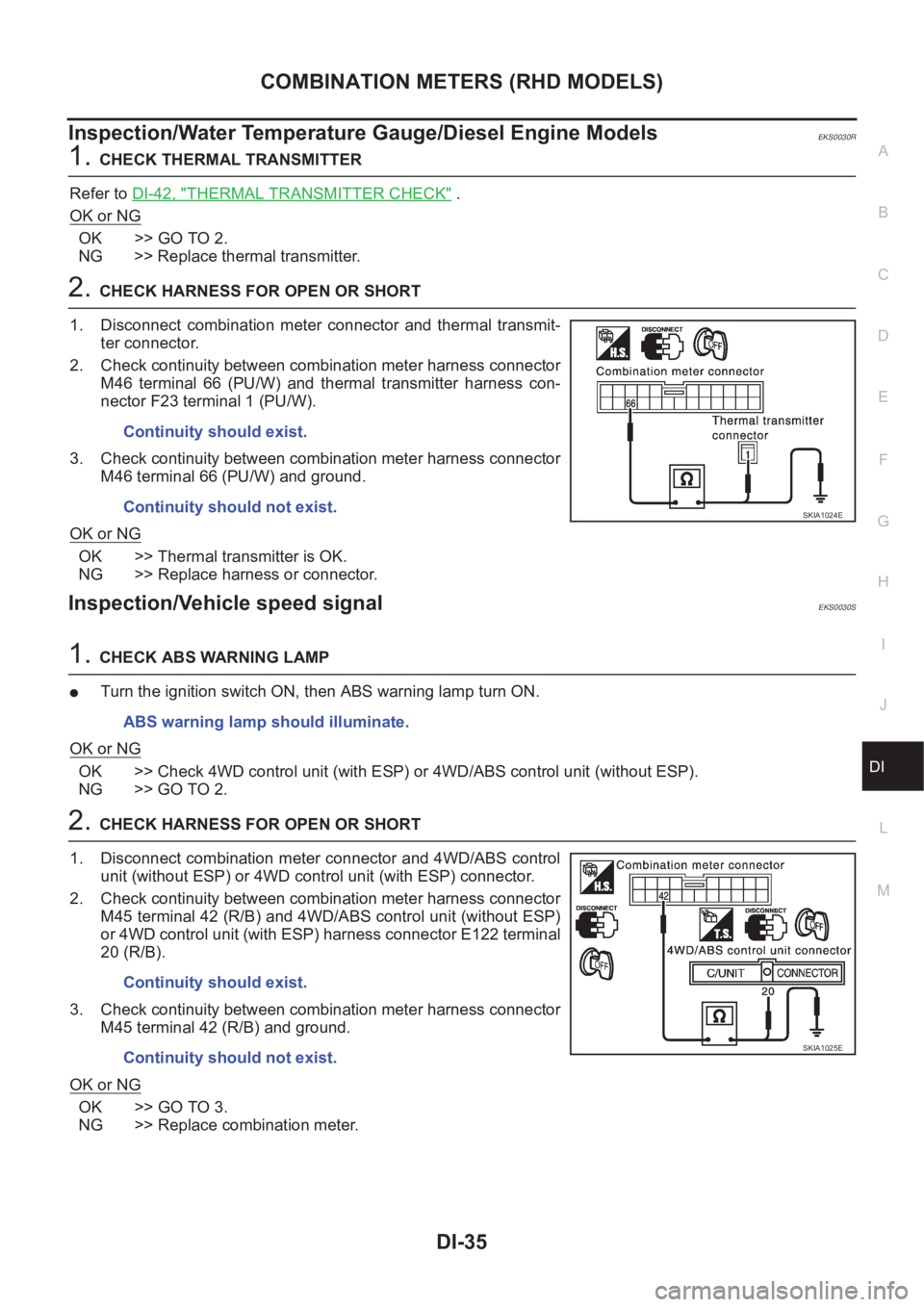
2.CHECK HARNESS FOR OPEN OR SHORT
1. Disconnect combination meter connector and thermal transmit-
ter connector.
2. Check continuity between combination meter harness connector
M46 terminal 66 (PU/W) and thermal transmitter harness con-
nector F23 terminal 1 (PU/W).
3. Check continuity between combination meter harness connector
M46 terminal 66 (PU/W) and ground.
OK or NG
OK >> Thermal transmitter is OK.
NG >> Replace harness or connector.
Inspection/Vehicle speed signalEKS0030S
1.CHECK ABS WARNING LAMP
●Turn the ignition switch ON, then ABS warning lamp turn ON.
OK or NG
OK >> Check 4WD control unit (with ESP) or 4WD/ABS control unit (without ESP).
NG >> GO TO 2.
2.CHECK HARNESS FOR OPEN OR SHORT
1. Disconnect combination meter connector and 4WD/ABS control
unit (without ESP) or 4WD control unit (with ESP) connector.
2. Check continuity between combination meter harness connector
M45 terminal 42 (R/B) and 4WD/ABS control unit (without ESP)
or 4WD control unit (with ESP) harness connector E122 terminal
20 (R/B).
3. Check continuity between combination meter harness connector
M45 terminal 42 (R/B) and ground.
OK or NG
OK >> GO TO 3.
NG >> Replace combination meter.Continuity should exist.
Continuity should not exist.
SKIA1024E
ABS warning lamp should illuminate.
Continuity should exist.
Continuity should not exist.
SKIA1025E
Page 3594 of 3833
DI-36
COMBINATION METERS (RHD MODELS)
3. CHECK 4WD/ABS CONTROL UNIT OUTPUT
1. Connect combination meter connector.
2. Check voltage between combination meter harness connector
M45 terminal 42 (R/B) and ground.
OK or NG
OK >> GO TO 4.
NG >> Replace combination meter.
4. CHECK VEHICLE SPEED INPUT SIGNAL
1. Connect 4WD/ABS control unit connector (without ESP) or 4WD
control unit (with ESP).
2. Lift up drive wheels.
3. Start engine.
4. Check voltage signal between combination meter harness con-
nector M45 terminal 42 (R/B) and ground (Use “SIMPLE OSCIL-
LOSCOPE” in “SUB MODE” with CONSULT-II.).
OK or NG
OK >> Replace combination meter.
NG >> Check 4WD control unit (with ESP) or 4WD/ABS control unit (without ESP). Approx. 9V
SKIA1026E
42 (R/B) – ground
SKIA0990E
Page 3662 of 3833
BCS-6
TIME CONTROL UNIT
NOTE:
*1: When seat pressure switch is ON.
*2: Wire color is different depending on vehicle. Each wire color are as follows:
30 R Front door switch (driver side) OFF (closed) → ON (open) 5V → 0V
31 R/W Passenger and rear doors switch OFF (closed) → ON (open) 5V → 0V
32 OR Multi-remote control unitRemote controller lock button is
pushed.
(Ignition switch is not at “ON” position)0V → 5V
33 P/L Multi-remote control unitRemote controller unlock button is
pushed.
(Ignition switch is not at “ON” position)0V → 5V
34 B/Y NATS release signal Ignition switch ON→OFF 0V→5V
35 LG/B Rear window defogger switch OFF → ON 5V → 0V
36 *2 Combination meterWhen the vehicle speed is approx.
40km (25MPH). Te r m i n a l
No.Wire
colorConnections Operation condition Voltage (Approximate values)
ELF1080D
Vehicle Wire color
A/T models :L/W
M/T models with gasoline engine :L/Y
Diesel engine models :L/B
Page 3665 of 3833
![NISSAN X-TRAIL 2001 Service Repair Manual CAN COMMUNICATION
LAN-3
[CAN]
C
D
E
F
G
H
I
J
L
MA
B
LAN
CAN COMMUNICATIONPFP:23710
System DescriptionEKS001U3
CAN (Controller Area Network) is a serial communication line for real time application. I NISSAN X-TRAIL 2001 Service Repair Manual CAN COMMUNICATION
LAN-3
[CAN]
C
D
E
F
G
H
I
J
L
MA
B
LAN
CAN COMMUNICATIONPFP:23710
System DescriptionEKS001U3
CAN (Controller Area Network) is a serial communication line for real time application. I](/manual-img/5/57405/w960_57405-3664.png)
CAN COMMUNICATION
LAN-3
[CAN]
C
D
E
F
G
H
I
J
L
MA
B
LAN
CAN COMMUNICATIONPFP:23710
System DescriptionEKS001U3
CAN (Controller Area Network) is a serial communication line for real time application. It is an on-vehicle mul-
tiplex communication line with high data communication speed and excellent error detection ability. Many elec-
tronic control units are equipped onto a vehicle, and each control unit shares information and links with other
control units during operation (not independent). In CAN communication, control units are connected with 2
communication lines (CAN H line, CAN L line) allowing a high rate of information transmission with less wiring.
Each control unit transmits/receives data but selectively reads required data only.
FOR A/T MODELS
System diagram
Input/output signal chart
T: Transmit R: Receive
FOR M/T MODELS
System diagram
Input/output signal chart
T: Transmit R: Receive
SKIA0884E
Signals ECM TCM
Engine coolant temperature signal T R
Accelerator pedal position signal T R
A/T self-diagnosis signal R T
SKIA0885E
Signals ECMSteering wheel
angle sensor4WD control unitESP/ TCS / ABS
control unit
Engine speed signal T R R
Accelerator pedal position signal T R
ESP operation signal R R T
TCS operation signal R R T
ABS operation signal R R T
Stop lamp switch signalRT
Steering wheel angle sensor signal T R
ESP-OFF switch signalRT
Page 3669 of 3833
![NISSAN X-TRAIL 2001 Service Repair Manual CAN SYSTEM (FOR A/T MODELS)
LAN-7
[CAN]
C
D
E
F
G
H
I
J
L
MA
B
LAN
Work FlowEKS002AG
1. Print all the data of “SELF-DIAG RESULTS” and “DATA MONITOR” for “ENGINE” and “A/T” displayed on NISSAN X-TRAIL 2001 Service Repair Manual CAN SYSTEM (FOR A/T MODELS)
LAN-7
[CAN]
C
D
E
F
G
H
I
J
L
MA
B
LAN
Work FlowEKS002AG
1. Print all the data of “SELF-DIAG RESULTS” and “DATA MONITOR” for “ENGINE” and “A/T” displayed on](/manual-img/5/57405/w960_57405-3668.png)
CAN SYSTEM (FOR A/T MODELS)
LAN-7
[CAN]
C
D
E
F
G
H
I
J
L
MA
B
LAN
Work FlowEKS002AG
1. Print all the data of “SELF-DIAG RESULTS” and “DATA MONITOR” for “ENGINE” and “A/T” displayed on
CONSULT-II. Refer to the following:
●EC-854, "DTC U1000 CAN COMMUNICATION LINE" (QR20 WITH EURO-OBD) for “ENGINE”
●EC-1199, "DTC U1000 CAN COMMUNICATION LINE" (QR20 WITHOUT EURO-OBD) for “ENGINE”
●EC-122, "DTC U1000 CAN COMMUNICATION LINE" (QR25 WITH EURO-OBD) for “ENGINE”
●EC-513, "DTC U1000 CAN COMMUNICATION LINE" (QR25 WITHOUT EURO-OBD) for “ENGINE”
●AT-190, "DTC U1000 CAN COMMUNICATION LINE" (EURO-OBD) for “A/T”
●AT-403, "CAN COMMUNICATION LINE" (ALL) for “A/T”
2. Attach the printed sheet of “SELF-DIAG RESULTS” and “DATA MONITOR” onto the check sheet. Refer to
LAN-8, "
CHECK SHEET" .
3. Based on the data monitor results, put “v” marks onto the items with “UNKWN” or “NG” in the check sheet
table. Refer to LAN-8, "
CHECK SHEET" .
NOTE:
If “NG” is displayed on “CAN COMM” for the diagnosed control unit, replace the control unit.
4. According to the check sheet results (example), start inspection. Refer to LAN-9, "
CHECK SHEET
RESULTS (EXAMPLE)" .
Page 3671 of 3833
![NISSAN X-TRAIL 2001 Service Repair Manual CAN SYSTEM (FOR A/T MODELS)
LAN-9
[CAN]
C
D
E
F
G
H
I
J
L
MA
B
LAN
CHECK SHEET RESULTS (EXAMPLE)
INSPECTION
Proceed trouble diagnosis according to the check sheet results (example).
Case 1:Replace ECM NISSAN X-TRAIL 2001 Service Repair Manual CAN SYSTEM (FOR A/T MODELS)
LAN-9
[CAN]
C
D
E
F
G
H
I
J
L
MA
B
LAN
CHECK SHEET RESULTS (EXAMPLE)
INSPECTION
Proceed trouble diagnosis according to the check sheet results (example).
Case 1:Replace ECM](/manual-img/5/57405/w960_57405-3670.png)
CAN SYSTEM (FOR A/T MODELS)
LAN-9
[CAN]
C
D
E
F
G
H
I
J
L
MA
B
LAN
CHECK SHEET RESULTS (EXAMPLE)
INSPECTION
Proceed trouble diagnosis according to the check sheet results (example).
Case 1:Replace ECM.
Case 2:Replace TCM.
Case 3:Check CAN communication circuit. Refer to LAN-9, "
CAN Communication Circuit Check" .
CAN Communication Circuit CheckEKS002AH
1.CHECK CONNECTOR
1. Turn ignition switch OFF.
2. Check following terminals and connector for damage, bend and loose connection (control module-side
and harness-side).
●TCM.
●ECM.
OK or NG
OK >> GO TO 2.
NG >> Repair terminal or connector.
2.CHECK HARNESS FOR SHORT CIRCUIT
1. Disconnect ECM connector and TCM connector.
2. Check the following.
●QR20DE engine models:
Continuity between ECM harness connector F43 terminals 33
(B/W) and 34 (L/R).
●QR25DE engine models:
Continuity between ECM harness connector F43 terminals 33
(W/B) and 34 (L/R).
OK or NG
OK >> GO TO 3.
NG >> Repair harness between ECM and TCM.
SKIA0887E
33 (B/W) – 34 (L/R)
(QR20DE engine models): Continuity should not
exist.
33 (W/B) – 34 (L/R)
(QR25DE engine models): Continuity should not
exist.
SKIA0888E
Page 3676 of 3833
![NISSAN X-TRAIL 2001 Service Repair Manual LAN-14
[CAN]
CAN SYSTEM (FOR M/T MODELS)
Work Flow
EKS002FN
1. Print all the data of “SELF-DIAG RESULTS” and “DATA MONITOR” for “ENGINE”, “ALL MODE 4WD”,
and “ABS” dis NISSAN X-TRAIL 2001 Service Repair Manual LAN-14
[CAN]
CAN SYSTEM (FOR M/T MODELS)
Work Flow
EKS002FN
1. Print all the data of “SELF-DIAG RESULTS” and “DATA MONITOR” for “ENGINE”, “ALL MODE 4WD”,
and “ABS” dis](/manual-img/5/57405/w960_57405-3675.png)
LAN-14
[CAN]
CAN SYSTEM (FOR M/T MODELS)
Work Flow
EKS002FN
1. Print all the data of “SELF-DIAG RESULTS” and “DATA MONITOR” for “ENGINE”, “ALL MODE 4WD”,
and “ABS” displayed on CONSULT-II. Refer to the following:
●EC-854, "DTC U1000 CAN COMMUNICATION LINE" (QR20 WITH EURO-OBD) for “ENGINE”
●EC-1199, "DTC U1000 CAN COMMUNICATION LINE" (QR20 WITHOUT EURO-OBD) for “ENGINE”
●EC-1448, "DTC U1000 CAN COMMUNICATION LINE" (YD) for “ENGINE”
●TF-53, "CAN COMMUNICATION SYSTEM" for “ALL MODE 4WD”
●BRC-110, "Inspection 15 CAN Communication Circuit, ESP/TCS/ABS Control Unit and Steering Wheel
Angle Sensor" for “ABS”
2. Attach the printed sheet of “SELF-DIAG RESULTS” and “DATA MONITOR” onto the check sheet. Refer to
LAN-15, "
CHECK SHEET" .
3. Based on the data monitor results, put “v” marks onto the items with “UNKWN” or “NG” in the check sheet
table. Refer to LAN-15, "
CHECK SHEET" .
NOTE:
If “NG” is displayed on “CAN COMM” for the diagnosed control unit, replace the control unit.
4. According to the check sheet results (example), start inspection. Refer to LAN-16, "
CHECK SHEET
RESULTS (EXAMPLE)" .