2001 NISSAN X-TRAIL engine control
[x] Cancel search: engine controlPage 3791 of 3833
PERIODIC MAINTENANCE
MA-11
C
D
E
F
G
H
I
J
K
MA
B
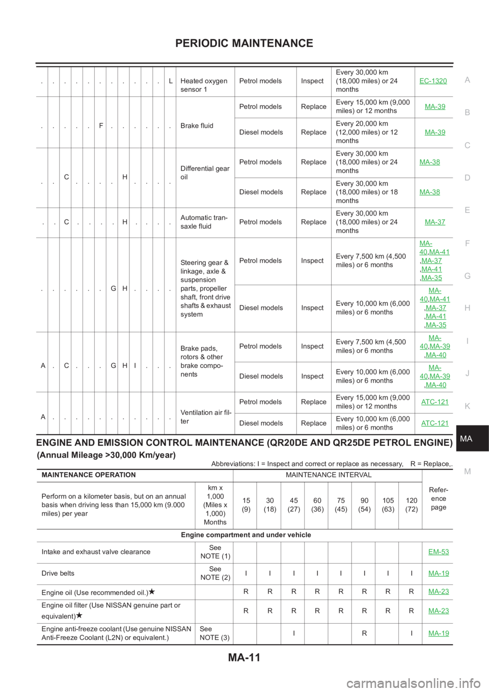
MAENGINE AND EMISSION CONTROL MAINTENANCE (QR20DE AND QR25DE PETROL ENGINE)
(Annual Mileage >30,000 Km/year)
Abbreviations: I = Inspect and correct or replace as necessary,R = Replace,. ...........LHeated oxygen
sensor 1Petrol models InspectEvery 30,000 km
(18,000 miles) or 24
monthsEC-1320
.....F......Brake fluidPetrol models ReplaceEvery 15,000 km (9,000
miles) or 12 monthsMA-39Diesel models ReplaceEvery 20,000 km
(12,000 miles) or 12
monthsMA-39
..C
....H
....Differential gear
oilPetrol models ReplaceEvery 30,000 km
(18,000 miles) or 24
monthsMA-38
Diesel models ReplaceEvery 30,000 km
(18,000 miles) or 18
monthsMA-38
..C....H....Automatic tran-
saxle fluidPetrol models ReplaceEvery 30,000 km
(18,000 miles) or 24
monthsMA-37
......GH....Steering gear &
linkage, axle &
suspension
parts, propeller
shaft, front drive
shafts & exhaust
systemPetrol models InspectEvery 7,500 km (4,500
miles) or 6 monthsMA-
40,MA-41
,MA-37
,MA-41
,MA-35
Diesel models InspectEvery 10,000 km (6,000
miles) or 6 monthsMA-
40,MA-41
,MA-37
,MA-41
,MA-35
A.C...GHI...Brake pads,
rotors & other
brake compo-
nentsPetrol models InspectEvery 7,500 km (4,500
miles) or 6 monthsMA-
40,MA-39
,MA-40
Diesel models InspectEvery 10,000 km (6,000
miles) or 6 monthsMA-40,MA-39
,MA-40
A...........Ventilation air fil-
terPetrol models ReplaceEvery 15,000 km (9,000
miles) or 12 monthsAT C - 1 2 1Diesel models ReplaceEvery 10,000 km (6,000
miles) or 6 monthsAT C - 1 2 1
MAINTENANCE OPERATIONMAINTENANCE INTERVAL
Refer-
ence
page Perform on a kilometer basis, but on an annual
basis when driving less than 15,000 km (9.000
miles) per yearkm x
1,000
(Miles x
1,000)
Months15
(9)30
(18)45
(27)60
(36)75
(45)90
(54)105
(63)120
(72)
Engine compartment and under vehicle
Intake and exhaust valve clearanceSee
NOTE (1)EM-53
Drive beltsSee
NOTE (2)II IIIIIIMA-19
Engine oil (Use recommended oil.)R RRRRRRRMA-23
Engine oil filter (Use NISSAN genuine part or
equivalent)R RRRRRRRMA-23
Engine anti-freeze coolant (Use genuine NISSAN
Anti-Freeze Coolant (L2N) or equivalent.)See
NOTE (3)IRIMA-19
Page 3793 of 3833
PERIODIC MAINTENANCE
MA-13
C
D
E
F
G
H
I
J
K
MA
B
MA
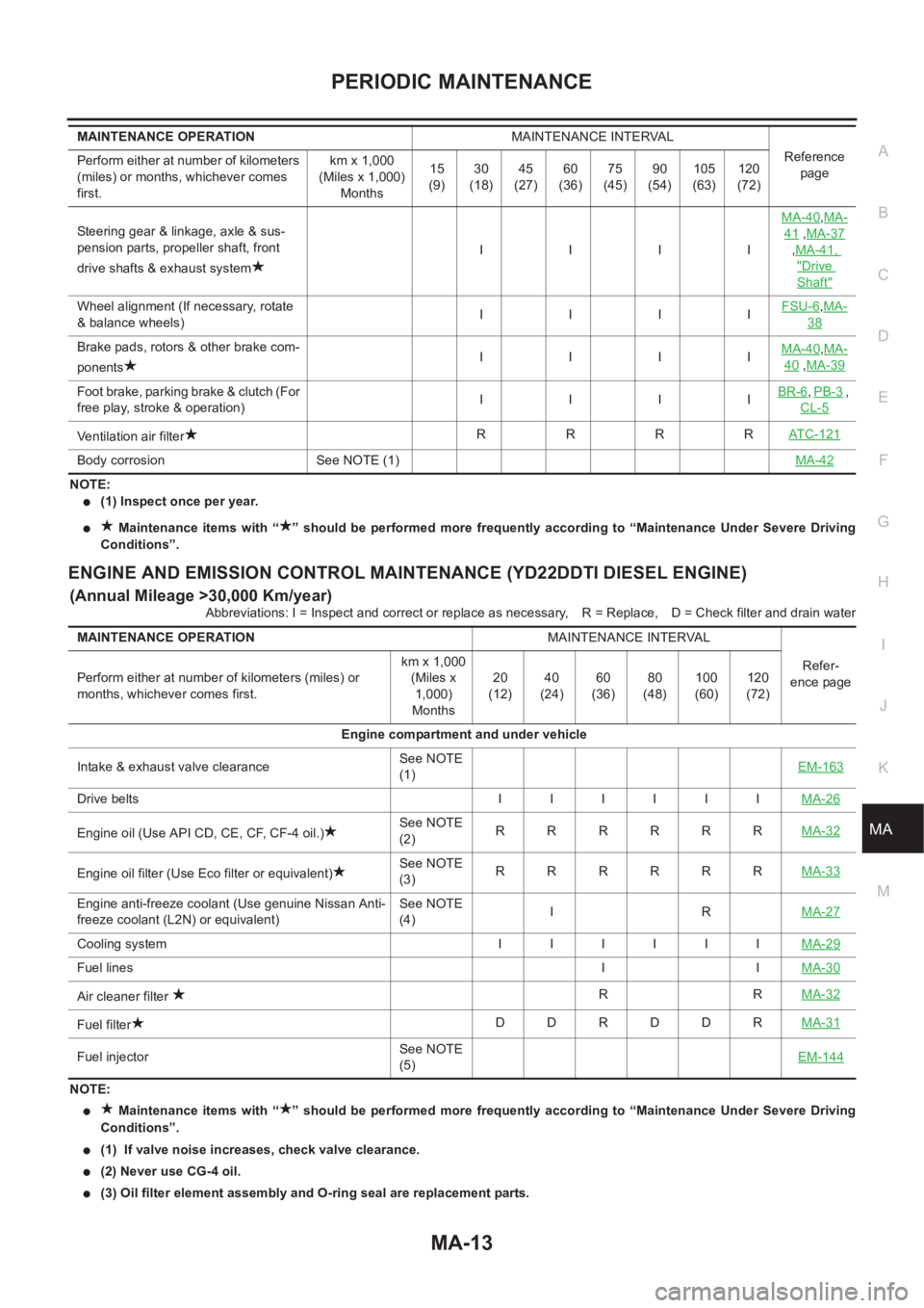
NOTE:
●(1) Inspect once per year.
● Maintenance items with “ ” should be performed more frequently according to “Maintenance Under Severe Driving
Conditions”.
ENGINE AND EMISSION CONTROL MAINTENANCE (YD22DDTI DIESEL ENGINE)
(Annual Mileage >30,000 Km/year)
Abbreviations: I = Inspect and correct or replace as necessary,R = Replace, D = Check filter and drain water
NOTE:
● Maintenance items with “ ” should be performed more frequently according to “Maintenance Under Severe Driving
Conditions”.
●(1) If valve noise increases, check valve clearance.
●(2) Never use CG-4 oil.
●(3) Oil filter element assembly and O-ring seal are replacement parts. Steering gear & linkage, axle & sus-
pension parts, propeller shaft, front
drive shafts & exhaust systemIIIIMA-40
,MA-
41 ,MA-37
,MA-41,
"Drive
Shaft"
Wheel alignment (If necessary, rotate
& balance wheels)IIIIFSU-6,MA-
38
Brake pads, rotors & other brake com-
ponentsIIIIMA-40,MA-
40 ,MA-39
Foot brake, parking brake & clutch (For
free play, stroke & operation)IIIIBR-6,PB-3 ,
CL-5
Ventilation air filterRRRRAT C - 1 2 1
Body corrosion See NOTE (1)MA-42
MAINTENANCE OPERATIONMAINTENANCE INTERVAL
Reference
page Perform either at number of kilometers
(miles) or months, whichever comes
first.km x 1,000
(Miles x 1,000)
Months15
(9)30
(18)45
(27)60
(36)75
(45)90
(54)105
(63)120
(72)
MAINTENANCE OPERATIONMAINTENANCE INTERVAL
Refer-
ence page Perform either at number of kilometers (miles) or
months, whichever comes first.km x 1,000
(Miles x
1,000)
Months20
(12)40
(24)60
(36)80
(48)100
(60)120
(72)
Engine compartment and under vehicle
Intake & exhaust valve clearanceSee NOTE
(1)EM-163
Drive belts I I I I I IMA-26
Engine oil (Use API CD, CE, CF, CF-4 oil.)See NOTE
(2)RRRRRRMA-32
Engine oil filter (Use Eco filter or equivalent)See NOTE
(3)RRRRRRMA-33
Engine anti-freeze coolant (Use genuine Nissan Anti-
freeze coolant (L2N) or equivalent)See NOTE
(4)IRMA-27
Cooling system I I I I I IMA-29
Fuel linesIIMA-30
Air cleaner filter RRMA-32
Fuel filterDDRDDRMA-31
Fuel injectorSee NOTE
(5)EM-144
Page 3800 of 3833
MA-20
ENGINE MAINTENANCE (QR20DE·QR25DE)
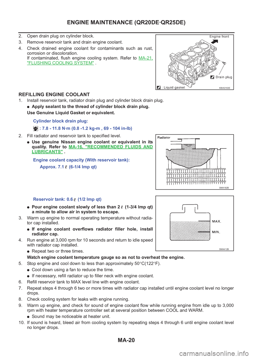
2. Open drain plug on cylinder block.
3. Remove reservoir tank and drain engine coolant.
4. Check drained engine coolant for contaminants such as rust,
corrosion or discoloration.
If contaminated, flush engine cooling system. Refer to MA-21,
"FLUSHING COOLING SYSTEM" .
REFILLING ENGINE COOLANT
1. Install reservoir tank, radiator drain plug and cylinder block drain plug.
●Apply sealant to the thread of cylinder block drain plug.
Use Genuine Liquid Gasket or equivalent.
2. Fill radiator and reservoir tank to specified level.
●Use genuine Nissan engine coolant or equivalent in its
quality. Refer to MA-16, "
RECOMMENDED FLUIDS AND
LUBRICANTS" .
●Pour engine coolant slowly of less than 2 (1-3/4 lmp qt)
a minute to allow air in system to escape.
3. Warm up engine to normal operating temperature without radia-
tor cap installed.
●If engine coolant overflows radiator filler hole, install
radiator cap.
4. Run engine at 3,000 rpm for 10 seconds and return to idle speed
with radiator cap installed.
●Repeat two or three times.
Watch engine coolant temperature gauge so as not to overheat the engine.
5. Stop engine and cool down to less than approximately 50°C(122°F).
●Cool down using a fan to reduce the time.
●If necessary, refill radiator up to filler neck with engine coolant.
6. Refill reservoir tank to MAX level line with engine coolant.
7. Repeat steps 4 through 6 two or more times with radiator cap installed until engine coolant level no longer
drops.
8. Check cooling system for leaks with engine running.
9. Warm up engine, and check for sound of engine coolant flow while running engine from idle up to 3,000
rpm with heater temperature controller set at several position between COOL and WARM.
●Sound may be noticeable at heater unit.
10. If sound is heard, bleed air from cooling system by repeating steps 4 through 6 until engine coolant level
no longer drops.
KBIA0163E
Cylinder block drain plug:
: 7.8 - 11.8 N·m (0.8 -1.2 kg-m , 69 - 104 in-lb)
Engine coolant capacity (With reservoir tank):
Approx. 7.1 (6-1/4 Imp qt)
SMA182B
Reservoir tank: 0.6 (1/2 lmp qt)
SMA412B
Page 3809 of 3833
ENGINE MAINTENANCE (YD22DDTI)
MA-29
C
D
E
F
G
H
I
J
K
MA
B
MA
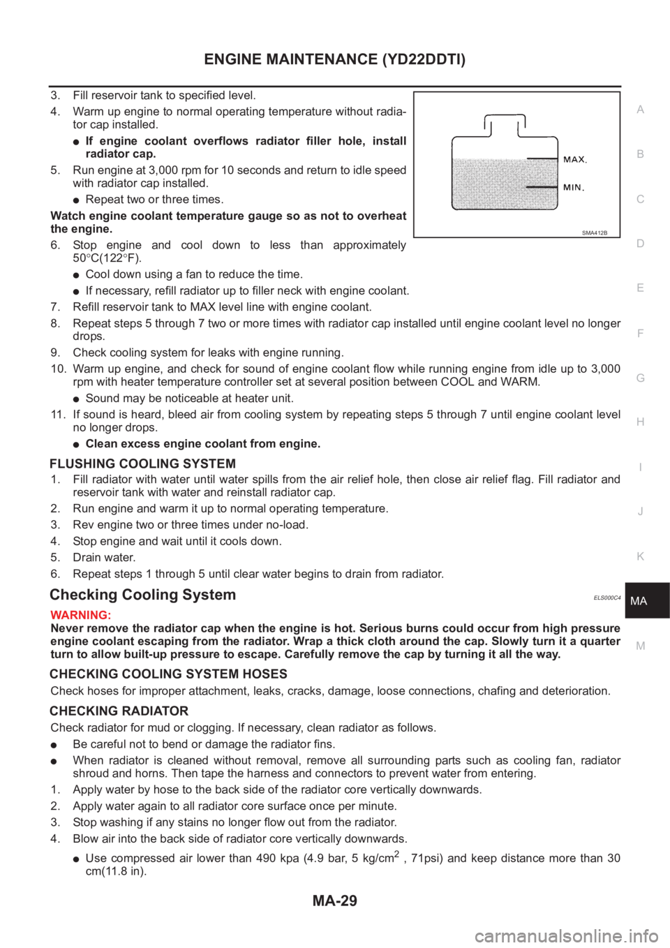
3. Fill reservoir tank to specified level.
4. Warm up engine to normal operating temperature without radia-
tor cap installed.
●If engine coolant overflows radiator filler hole, install
radiator cap.
5. Run engine at 3,000 rpm for 10 seconds and return to idle speed
with radiator cap installed.
●Repeat two or three times.
Watch engine coolant temperature gauge so as not to overheat
the engine.
6. Stop engine and cool down to less than approximately
50°C(122°F).
●Cool down using a fan to reduce the time.
●If necessary, refill radiator up to filler neck with engine coolant.
7. Refill reservoir tank to MAX level line with engine coolant.
8. Repeat steps 5 through 7 two or more times with radiator cap installed until engine coolant level no longer
drops.
9. Check cooling system for leaks with engine running.
10. Warm up engine, and check for sound of engine coolant flow while running engine from idle up to 3,000
rpm with heater temperature controller set at several position between COOL and WARM.
●Sound may be noticeable at heater unit.
11. If sound is heard, bleed air from cooling system by repeating steps 5 through 7 until engine coolant level
no longer drops.
●Clean excess engine coolant from engine.
FLUSHING COOLING SYSTEM
1. Fill radiator with water until water spills from the air relief hole, then close air relief flag. Fill radiator and
reservoir tank with water and reinstall radiator cap.
2. Run engine and warm it up to normal operating temperature.
3. Rev engine two or three times under no-load.
4. Stop engine and wait until it cools down.
5. Drain water.
6. Repeat steps 1 through 5 until clear water begins to drain from radiator.
Checking Cooling SystemELS000C4
WARNING:
Never remove the radiator cap when the engine is hot. Serious burns could occur from high pressure
engine coolant escaping from the radiator. Wrap a thick cloth around the cap. Slowly turn it a quarter
turn to allow built-up pressure to escape. Carefully remove the cap by turning it all the way.
CHECKING COOLING SYSTEM HOSES
Check hoses for improper attachment, leaks, cracks, damage, loose connections, chafing and deterioration.
CHECKING RADIATOR
Check radiator for mud or clogging. If necessary, clean radiator as follows.
●Be careful not to bend or damage the radiator fins.
●When radiator is cleaned without removal, remove all surrounding parts such as cooling fan, radiator
shroud and horns. Then tape the harness and connectors to prevent water from entering.
1. Apply water by hose to the back side of the radiator core vertically downwards.
2. Apply water again to all radiator core surface once per minute.
3. Stop washing if any stains no longer flow out from the radiator.
4. Blow air into the back side of radiator core vertically downwards.
●Use compressed air lower than 490 kpa (4.9 bar, 5 kg/cm2 , 71psi) and keep distance more than 30
cm(11.8 in).
SMA412B
Page 3827 of 3833
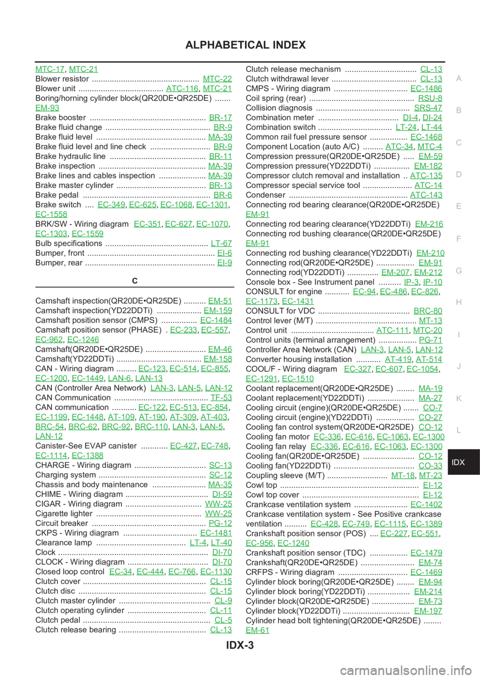
IDX-3
A
C
D
E
F
G
H
I
J
K
L B
IDX
ALPHABETICAL INDEX
MTC-17,MTC-21
Blower resistor ................................................ MTC-22
Blower unit ...................................... ATC-116,MTC-21
Boring/horning cylinder block(QR20DE•QR25DE) .......
EM-93
Brake booster .................................................... BR-17
Brake fluid change ............................................... BR-9
Brake fluid level ................................................. MA-39
Brake fluid level and line check ........................... BR-9
Brake hydraulic line ........................................... BR-11
Brake inspection ................................................ MA-39
Brake lines and cables inspection ..................... MA-39
Brake master cylinder ........................................ BR-13
Brake pedal ......................................................... BR-6
Brake switch .... EC-349,EC-625,EC-1068,EC-1301,
EC-1558
BRK/SW - Wiring diagram EC-351,EC-627,EC-1070,
EC-1303
,EC-1559
Bulb specifications .............................................. LT-67
Bumper, front ......................................................... EI-6
Bumper, rear .......................................................... EI-9
C
Camshaft inspection(QR20DE•QR25DE) .......... EM-51
Camshaft inspection(YD22DDTi) .................... EM-159
Camshaft position sensor (CMPS) ................ EC-1484
Camshaft position sensor (PHASE) . EC-233,EC-557,
EC-962
,EC-1246
Camshaft(QR20DE•QR25DE) ........................... EM-46
Camshaft(YD22DDTi) ...................................... EM-158
CAN - Wiring diagram ......... EC-123,EC-514,EC-855,
EC-1200
,EC-1449,LAN-6,LAN-13
CAN (Controller Area Network) LAN-3,LAN-5,LAN-12
CAN Communication .......................................... TF-53
CAN communication ........... EC-122,EC-513,EC-854,
EC-1199
,EC-1448,AT-109,AT-190,AT-309,AT-403,
BRC-54
,BRC-62,BRC-92,BRC-110,LAN-3,LAN-5,
LAN-12
Canister-See EVAP canister ............ EC-427,EC-748,
EC-1114
,EC-1388
CHARGE - Wiring diagram ................................ SC-13
Charging system ................................................ SC-12
Chassis and body maintenance ........................ MA-35
CHIME - Wiring diagram ..................................... DI-59
CIGAR - Wiring diagram .................................. WW-25
Cigarette lighter ............................................... WW-25
Circuit breaker ................................................... PG-12
CKPS - Wiring diagram ................................. EC-1481
Clearance lamp ........................................ LT-4,LT-40
Clock ................................................................... DI-70
CLOCK - Wiring diagram .................................... DI-70
Closed loop control EC-34,EC-444,EC-766,EC-1130
Clutch cover ....................................................... CL-15
Clutch disc ......................................................... CL-15
Clutch master cylinder ......................................... CL-9
Clutch operating cylinder ................................... CL-11
Clutch pedal ......................................................... CL-5
Clutch release bearing ....................................... CL-13
Clutch release mechanism ................................ CL-13
Clutch withdrawal lever ...................................... CL-13
CMPS - Wiring diagram ................................. EC-1486
Coil spring (rear) ............................................... RSU-8
Collision diagnosis .......................................... SRS-47
Combination meter .................................... DI-4,DI-24
Combination switch ................................. LT-24,LT-44
Common rail fuel pressure sensor ................. EC-1468
Component Location (auto A/C) ......... ATC-34,MTC-4
Compression pressure(QR20DE•QR25DE) ..... EM-59
Compression pressure(YD22DDTi) ................ EM-182
Compressor clutch removal and installation .. ATC-135
Compressor special service tool ...................... ATC-14
Condenser ..................................................... ATC-143
Connecting rod bearing clearance(QR20DE•QR25DE)
EM-91
Connecting rod bearing clearance(YD22DDTi) EM-216
Connecting rod bushing clearance(QR20DE•QR25DE)
EM-91
Connecting rod bushing clearance(YD22DDTi) EM-210
Connecting rod(QR20DE•QR25DE) ................. EM-91
Connecting rod(YD22DDTi) .............. EM-207,EM-212
Console box - See Instrument panel .......... IP-3,IP-10
CONSULT for engine ........... EC-94,EC-486,EC-826,
EC-1173
,EC-1431
CONSULT for VDC ......................................... BRC-80
Control lever (M/T) ............................................. MT-13
Control unit ..................................... ATC-111,MTC-20
Control units (terminal arrangement) ................. PG-71
Controller Area Network (CAN) LAN-3,LAN-5,LAN-12
Converter housing installation ........... AT-419,AT-514
COOL/F - Wiring diagram EC-327,EC-607,EC-1054,
EC-1291
,EC-1510
Coolant replacement(QR20DE•QR25DE) ........ MA-19
Coolant replacement(YD22DDTi) ..................... MA-27
Cooling circuit (engine)(QR20DE•QR25DE) ....... CO-7
Cooling circuit (engine)(YD22DDTi) ................. CO-27
Cooling fan control system(QR20DE•QR25DE) CO-12
Cooling fan motor EC-336,EC-616,EC-1063,EC-1300
Cooling fan relay EC-336,EC-616,EC-1063,EC-1300
Cooling fan(QR20DE•QR25DE) ....................... CO-12
Cooling fan(YD22DDTi) .................................... CO-33
Coupling sleeve (M/T) ........................... MT-18,MT-23
Cowl top .............................................................. EI-12
Cowl top cover .................................................... EI-12
Crankcase ventilation system ........................ EC-1402
Crankcase ventilation system - See Positive crankcase
ventilation .......... EC-428
,EC-749,EC-1115,EC-1389
Crankshaft position sensor (POS) .... EC-227,EC-551,
EC-956
,EC-1240
Crankshaft position sensor (TDC) ................. EC-1479
Crankshaft(QR20DE•QR25DE) ........................ EM-74
CRFPS - Wiring diagram ............................... EC-1469
Cylinder block boring(QR20DE•QR25DE) ........ EM-94
Cylinder block boring(YD22DDTi) ................... EM-214
Cylinder block(QR20DE•QR25DE) ................... EM-73
Cylinder block(YD22DDTi) .............................. EM-197
Cylinder head bolt tightening(QR20DE•QR25DE) ........
EM-61
Page 3828 of 3833
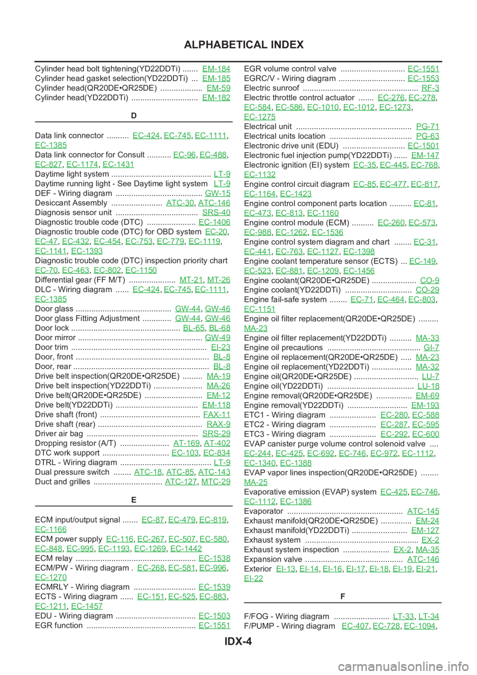
IDX-4
ALPHABETICAL INDEX
Cylinder head bolt tightening(YD22DDTi) ....... EM-184
Cylinder head gasket selection(YD22DDTi) ... EM-185
Cylinder head(QR20DE•QR25DE) ................... EM-59
Cylinder head(YD22DDTi) .............................. EM-182
D
Data link connector .......... EC-424
,EC-745,EC-1111,
EC-1385
Data link connector for Consult ........... EC-96,EC-488,
EC-827
,EC-1174,EC-1431
Daytime light system ............................................. LT-9
Daytime running light - See Daytime light system LT-9
DEF - Wiring diagram ....................................... GW-15
Desiccant Assembly ....................... ATC-30,ATC-146
Diagnosis sensor unit ..................................... SRS-40
Diagnostic trouble code (DTC) ...................... EC-1406
Diagnostic trouble code (DTC) for OBD system EC-20,
EC-47
,EC-432,EC-454,EC-753,EC-779,EC-1119,
EC-1141
,EC-1393
Diagnostic trouble code (DTC) inspection priority chart
EC-70
,EC-463,EC-802,EC-1150
Differential gear (FF M/T) ..................... MT-21,MT-26
DLC - Wiring diagram ...... EC-424,EC-745,EC-1111,
EC-1385
Door glass ........................................... GW-44,GW-46
Door glass Fitting Adjustment ............. GW-44,GW-46
Door lock ................................................. BL-65,BL-68
Door mirror ........................................................ GW-49
Door trim ............................................................. EI-23
Door, front ............................................................ BL-8
Door, rear ............................................................. BL-8
Drive belt inspection(QR20DE•QR25DE) ......... MA-19
Drive belt inspection(YD22DDTi) ...................... MA-26
Drive belt(QR20DE•QR25DE) .......................... EM-12
Drive belt(YD22DDTi) ..................................... EM-118
Drive shaft (front) ............................................. FAX-11
Drive shaft (rear) ............................................... RAX-9
Driver air bag .................................................. SRS-29
Dropping resistor (A/T) ...................... AT-169,AT-402
DTC work support .............................. EC-103,EC-834
DTRL - Wiring diagram ......................................... LT-9
Dual pressure switch ........ ATC-18,ATC-85,ATC-143
Duct and grilles ............................... ATC-127,MTC-29
E
ECM input/output signal ....... EC-87
,EC-479,EC-819,
EC-1166
ECM power supply EC-116,EC-267,EC-507,EC-580,
EC-848
,EC-995,EC-1193,EC-1269,EC-1442
ECM relay ...................................................... EC-1538
ECM/PW - Wiring diagram . EC-268,EC-581,EC-996,
EC-1270
ECMRLY - Wiring diagram ............................ EC-1539
ECTS - Wiring diagram ...... EC-151,EC-525,EC-883,
EC-1211
,EC-1457
EDU - Wiring diagram .................................... EC-1503
EGR function ................................................. EC-1551
EGR volume control valve ............................. EC-1551
EGRC/V - Wiring diagram .............................. EC-1553
Electric sunroof .................................................... RF-3
Electric throttle control actuator ....... EC-276,EC-278,
EC-584
,EC-586,EC-1010,EC-1012,EC-1273,
EC-1275
Electrical unit .................................................... PG-71
Electrical units location ..................................... PG-63
Electronic drive unit (EDU) ............................ EC-1501
Electronic fuel injection pump(YD22DDTi) ...... EM-147
Electronic ignition (EI) system EC-35,EC-445,EC-768,
EC-1132
Engine control circuit diagram EC-85,EC-477,EC-817,
EC-1164
,EC-1423
Engine control component parts location .......... EC-81,
EC-473
,EC-813,EC-1160
Engine control module (ECM) .......... EC-260,EC-573,
EC-988
,EC-1262,EC-1536
Engine control system diagram and chart ........ EC-31,
EC-441
,EC-763,EC-1127,EC-1398
Engine coolant temperature sensor (ECTS) ... EC-149,
EC-523
,EC-881,EC-1209,EC-1456
Engine coolant(QR20DE•QR25DE) .................... CO-9
Engine coolant(YD22DDTi) .............................. CO-29
Engine fail-safe system ........ EC-71,EC-464,EC-803,
EC-1151
Engine oil filter replacement(QR20DE•QR25DE) .........
MA-23
Engine oil filter replacement(YD22DDTi) .......... MA-33
Engine oil precautions .......................................... GI-7
Engine oil replacement(QR20DE•QR25DE) ..... MA-23
Engine oil replacement(YD22DDTi) .................. MA-32
Engine oil(QR20DE•QR25DE) ............................. LU-7
Engine oil(YD22DDTi) ....................................... LU-18
Engine removal(QR20DE•QR25DE) ................ EM-69
Engine removal(YD22DDTi) ........................... EM-193
ETC1 - Wiring diagram ..................... EC-280,EC-588
ETC2 - Wiring diagram ..................... EC-287,EC-595
ETC3 - Wiring diagram ..................... EC-292,EC-600
EVAP canister purge volume control solenoid valve ....
EC-244
,EC-425,EC-692,EC-746,EC-972,EC-1112,
EC-1340
,EC-1388
EVAP vapor lines inspection(QR20DE•QR25DE) ........
MA-25
Evaporative emission (EVAP) system EC-425,EC-746,
EC-1112
,EC-1386
Evaporator .................................................... ATC-145
Exhaust manifold(QR20DE•QR25DE) .............. EM-24
Exhaust manifold(YD22DDTi) ......................... EM-127
Exhaust system ................................................... EX-2
Exhaust system inspection ..................... EX-2,MA-35
Expansion valve ............................................ ATC-146
Exterior EI-13,EI-14,EI-16,EI-17,EI-18,EI-19,EI-21,
EI-22
F
F/FOG - Wiring diagram ......................... LT-33
,LT-34
F/PUMP - Wiring diagram EC-407,EC-728,EC-1094,
Page 3829 of 3833
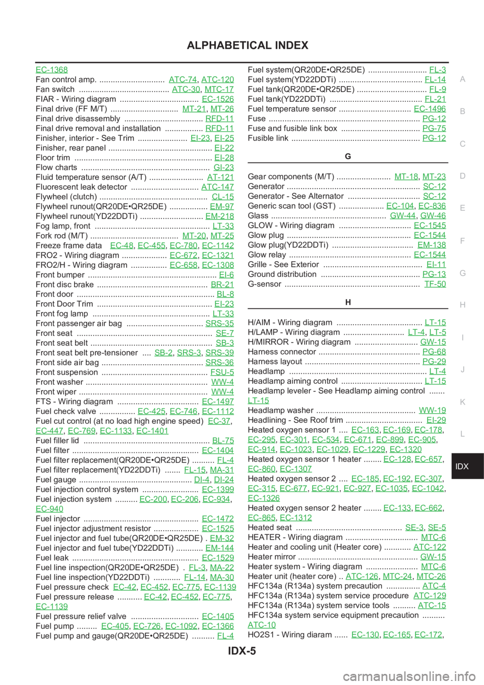
IDX-5
A
C
D
E
F
G
H
I
J
K
L B
IDX
ALPHABETICAL INDEX
EC-1368
Fan control amp. ............................. ATC-74,ATC-120
Fan switch ........................................ ATC-30,MTC-17
FIAR - Wiring diagram ................................... EC-1526
Final drive (FF M/T) .............................. MT-21,MT-26
Final drive disassembly ................................... RFD-11
Final drive removal and installation ................. RFD-11
Finisher, interior - See Trim ...................... EI-23,EI-25
Finisher, rear panel .............................................. EI-22
Floor trim ............................................................. EI-28
Flow charts ......................................................... GI-23
Fluid temperature sensor (A/T) ........................ AT-121
Fluorescent leak detector .............................. ATC-147
Flywheel (clutch) ................................................ CL-15
Flywheel runout(QR20DE•QR25DE) ................. EM-97
Flywheel runout(YD22DDTi) ............................ EM-218
Fog lamp, front ................................................... LT-33
Fork rod (M/T) ....................................... MT-20,MT-25
Freeze frame data EC-48,EC-455,EC-780,EC-1142
FRO2 - Wiring diagram .................... EC-672,EC-1321
FRO2/H - Wiring diagram ................ EC-658,EC-1308
Front bumper ......................................................... EI-6
Front disc brake ................................................. BR-21
Front door ............................................................. BL-8
Front Door Trim ................................................... EI-23
Front fog lamp .................................................... LT-33
Front passenger air bag .................................. SRS-35
Front seat ............................................................ SE-7
Front seat belt ...................................................... SB-3
Front seat belt pre-tensioner .... SB-2,SRS-3,SRS-39
Front side air bag ............................................. SRS-36
Front suspension ............................................... FSU-5
Front washer ...................................................... WW-4
Front wiper ......................................................... WW-4
FTS - Wiring diagram .................................... EC-1497
Fuel check valve ................ EC-425,EC-746,EC-1112
Fuel cut control (at no load high engine speed) EC-37,
EC-447
,EC-769,EC-1133,EC-1401
Fuel filler lid ........................................................ BL-75
Fuel filter ........................................................ EC-1404
Fuel filter replacement(QR20DE•QR25DE) .......... FL-4
Fuel filter replacement(YD22DDTi) ....... FL-15,MA-31
Fuel gauge .................................................. DI-4,DI-24
Fuel injection control system ......................... EC-1399
Fuel injection system .......... EC-200,EC-206,EC-934,
EC-940
Fuel injector ................................................... EC-1472
Fuel injector adjustment resistor .................... EC-1525
Fuel injector and fuel tube(QR20DE•QR25DE) . EM-32
Fuel injector and fuel tube(YD22DDTi) ............ EM-144
Fuel leak ........................................................ EC-1529
Fuel line inspection(QR20DE•QR25DE) . FL-3,MA-22
Fuel line inspection(YD22DDTi) ............ FL-14,MA-30
Fuel pressure check EC-42,EC-452,EC-775,EC-1139
Fuel pressure release ........... EC-42,EC-452,EC-775,
EC-1139
Fuel pressure relief valve .............................. EC-1405
Fuel pump ......... EC-405,EC-726,EC-1092,EC-1366
Fuel pump and gauge(QR20DE•QR25DE) .......... FL-4
Fuel system(QR20DE•QR25DE) .......................... FL-3
Fuel system(YD22DDTi) ..................................... FL-14
Fuel tank(QR20DE•QR25DE) ............................... FL-9
Fuel tank(YD22DDTi) ......................................... FL-21
Fuel temperature sensor ................................ EC-1496
Fuse ................................................................... PG-12
Fuse and fusible link box ................................... PG-75
Fusible link ......................................................... PG-12
G
Gear components (M/T) ........................ MT-18
,MT-23
Generator ........................................................... SC-12
Generator - See Alternator ................................ SC-12
Generic scan tool (GST) .................... EC-104,EC-836
Glass ................................................... GW-44,GW-46
GLOW - Wiring diagram ................................ EC-1545
Glow plug ....................................................... EC-1544
Glow plug(YD22DDTi) .................................... EM-138
Glow relay ...................................................... EC-1544
Grille - See Exterior ............................................ EI-11
Ground distribution ............................................ PG-13
G-sensor ............................................................ TF-50
H
H/AIM - Wiring diagram ...................................... LT-15
H/LAMP - Wiring diagram ........................... LT-4,LT-5
H/MIRROR - Wiring diagram ............................ GW-15
Harness connector ............................................. PG-68
Harness layout ................................................... PG-29
Headlamp ............................................................. LT-4
Headlamp aiming control .................................... LT-15
Headlamp leveler - See Headlamp aiming control .......
LT-15
Headlamp washer ............................................ WW-19
Headlining - See Roof trim .................................. EI-29
Heated oxygen sensor 1 .... EC-163,EC-169,EC-178,
EC-295
,EC-301,EC-534,EC-671,EC-899,EC-905,
EC-914
,EC-1023,EC-1029,EC-1229,EC-1320
Heated oxygen sensor 1 heater ........ EC-128,EC-657,
EC-860
,EC-1307
Heated oxygen sensor 2 .... EC-185,EC-192,EC-307,
EC-315
,EC-677,EC-921,EC-927,EC-1035,EC-1042,
EC-1326
Heated oxygen sensor 2 heater ........ EC-133,EC-662,
EC-865
,EC-1312
Heated seat ............................................... SE-3,SE-5
HEATER - Wiring diagram ................................ MTC-6
Heater and cooling unit (Heater core) ............ ATC-122
Heater mirror ..................................................... GW-15
Heater system - Wiring diagram ....................... MTC-6
Heater unit (heater core) .. ATC-126,MTC-24,MTC-26
HFC134a (R134a) system precaution ............... ATC-4
HFC134a (R134a) system service procedure ATC-129
HFC134a (R134a) system service tools .......... ATC-15
HFC134a system service equipment precaution ..........
ATC-10
HO2S1 - Wiring diaram ...... EC-130,EC-165,EC-172,
Page 3830 of 3833
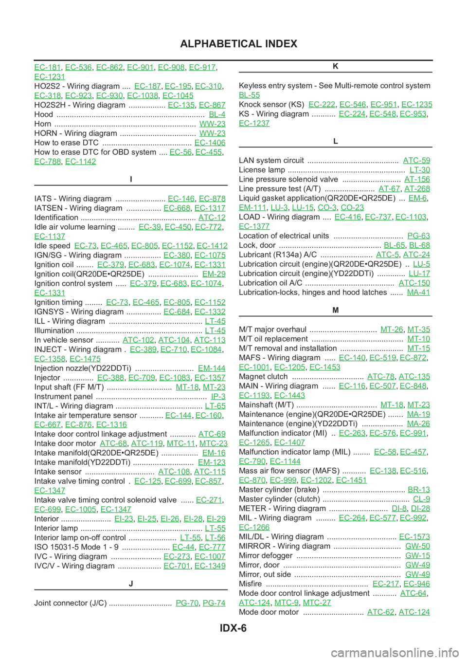
IDX-6
ALPHABETICAL INDEX
EC-181,EC-536,EC-862,EC-901,EC-908,EC-917,
EC-1231
HO2S2 - Wiring diagram .... EC-187,EC-195,EC-310,
EC-318
,EC-923,EC-930,EC-1038,EC-1045
HO2S2H - Wiring diagram ................. EC-135,EC-867
Hood .................................................................... BL-4
Horn ................................................................. WW-23
HORN - Wiring diagram ................................... WW-23
How to erase DTC ......................................... EC-1406
How to erase DTC for OBD system .... EC-56,EC-455,
EC-788
,EC-1142
I
IATS - Wiring diagram ....................... EC-146
,EC-878
IATSEN - Wiring diagram ................ EC-668,EC-1317
Identification ..................................................... ATC-12
Idle air volume learning ........ EC-39,EC-450,EC-772,
EC-1137
Idle speed EC-73,EC-465,EC-805,EC-1152,EC-1412
IGN/SG - Wiring diagram ................. EC-380,EC-1075
Ignition coil ........ EC-379,EC-683,EC-1074,EC-1331
Ignition coil(QR20DE•QR25DE) ....................... EM-29
Ignition control system ..... EC-379,EC-683,EC-1074,
EC-1331
Ignition timing ........ EC-73,EC-465,EC-805,EC-1152
IGNSYS - Wiring diagram ................ EC-684,EC-1332
ILL - Wiring diagram ........................................... LT-45
Illumination .......................................................... LT-45
In vehicle sensor ........... ATC-102,ATC-104,ATC-113
INJECT - Wiring diagram . EC-389,EC-710,EC-1084,
EC-1358
,EC-1475
Injection nozzle(YD22DDTi) ........................... EM-144
Injector .............. EC-388,EC-709,EC-1083,EC-1357
Input shaft (FF M/T) .............................. MT-18,MT-23
Instrument panel ................................................... IP-3
INT/L - Wiring diagram ........................................ LT-65
Intake air temperature sensor ........... EC-144,EC-160,
EC-667
,EC-876,EC-1316
Intake door control linkage adjustment ............ ATC-69
Intake door motor ATC-68,ATC-119,MTC-11,MTC-23
Intake manifold(QR20DE•QR25DE) ................. EM-16
Intake manifold(YD22DDTi) ............................ EM-123
Intake sensor ................................ ATC-108,ATC-115
Intake valve timing control . EC-125,EC-699,EC-857,
EC-1347
Intake valve timing control solenoid valve ...... EC-271,
EC-699
,EC-1005,EC-1347
Interior ....................... EI-23,EI-25,EI-26,EI-28,EI-29
Interior lamp ........................................................ LT-55
Interior lamp on-off control ...................... LT-55,LT-56
ISO 15031-5 Mode 1 - 9 ...................... EC-44,EC-777
IVC - Wiring diagram ....................... EC-273,EC-1007
IVC/V - Wiring diagram .................... EC-701,EC-1349
J
Joint connector (J/C) ............................. PG-70
,PG-74
K
Keyless entry system - See Multi-remote control system
BL-55
Knock sensor (KS) EC-222,EC-546,EC-951,EC-1235
KS - Wiring diagram ........... EC-224,EC-548,EC-953,
EC-1237
L
LAN system circuit .......................................... ATC-59
License lamp ...................................................... LT-30
Line pressure solenoid valve ........................... AT-156
Line pressure test (A/T) ....................... AT-67,AT-268
Liquid gasket application(QR20DE•QR25DE) ... EM-6,
EM-111
,LU-3,LU-15,CO-3,CO-23
LOAD - Wiring diagram .... EC-416,EC-737,EC-1103,
EC-1377
Location of electrical units ................................ PG-63
Lock, door ............................................... BL-65,BL-68
Lubricant (R134a) A/C ........................ ATC-5,ATC-24
Lubrication circuit (engine)(QR20DE•QR25DE) .. LU-5
Lubrication circuit (engine)(YD22DDTi) ............. LU-17
Lubrication oil A/C ......................................... ATC-150
Lubrication-locks, hinges and hood latches ...... MA-41
M
M/T major overhaul ............................... MT-26
,MT-35
M/T oil replacement .......................................... MT-10
M/T removal and installation ............................. MT-15
MAFS - Wiring diagram ..... EC-140,EC-519,EC-872,
EC-1001
,EC-1205,EC-1453
Magnet clutch ................................. ATC-78,ATC-135
MAIN - Wiring diagram ...... EC-116,EC-507,EC-848,
EC-1193
,EC-1443
Mainshaft (M/T) ..................................... MT-18,MT-23
Maintenance (engine)(QR20DE•QR25DE) ....... MA-19
Maintenance (engine)(YD22DDTi) ................... MA-26
Malfunction indicator (MI) .. EC-263,EC-576,EC-991,
EC-1265
,EC-1407
Malfunction indicator lamp (MIL) ........ EC-58,EC-457,
EC-790
,EC-1144
Mass air flow sensor (MAFS) ........... EC-138,EC-516,
EC-870
,EC-999,EC-1202,EC-1451
Master cylinder (brake) ...................................... BR-13
Master cylinder (clutch) ........................................ CL-9
METER - Wiring diagram ........................... DI-8,DI-28
MIL - Wiring diagram ......... EC-264,EC-577,EC-992,
EC-1266
MIL/DL - Wiring diagram ................................ EC-1573
MIRROR - Wiring diagram ............................... GW-50
Mirror defogger ................................................ GW-15
Mirror, door ...................................................... GW-49
Mirror, out side ................................................. GW-49
Misfire ............................................... EC-217,EC-946
Mode door control linkage adjustment ........... ATC-64,
ATC-124
,MTC-9,MTC-27
Mode door motor ............................ ATC-62,ATC-124