2001 NISSAN X-TRAIL engine control
[x] Cancel search: engine controlPage 2891 of 3833
![NISSAN X-TRAIL 2001 Service Repair Manual TROUBLE DIAGNOSIS
BRC-107
[ESP/TCS/ABS]
C
D
E
G
H
I
J
K
L
MA
B
BRC
2.SELF-DIAGNOSIS RESULT CHECK 2
1. Disconnect the ESP/TCS/ABS control unit connector. Securely connect them again.
2. Perform the sel NISSAN X-TRAIL 2001 Service Repair Manual TROUBLE DIAGNOSIS
BRC-107
[ESP/TCS/ABS]
C
D
E
G
H
I
J
K
L
MA
B
BRC
2.SELF-DIAGNOSIS RESULT CHECK 2
1. Disconnect the ESP/TCS/ABS control unit connector. Securely connect them again.
2. Perform the sel](/manual-img/5/57405/w960_57405-2890.png)
TROUBLE DIAGNOSIS
BRC-107
[ESP/TCS/ABS]
C
D
E
G
H
I
J
K
L
MA
B
BRC
2.SELF-DIAGNOSIS RESULT CHECK 2
1. Disconnect the ESP/TCS/ABS control unit connector. Securely connect them again.
2. Perform the self-diagnosis.
Is the same self-diagnosis item indicated?
YES >> GO TO 3.
NO >> Repair or replace the poorly connected connector.
3.ESP/TCS/ABS CONTROL UNIT POWER SUPPLY CIRCUIT INSPECTION 1
1. Disconnect the ESP/TCS/ABS control unit connector.
2. Turn the ignition switch ON (engine not running), and check the
voltage between the ESP/TCS/ABS control unit (vehicle-side
connector B111) and body ground.
Is inspection result OK?
YES >> GO TO 4.
NO >> GO TO 5.
4.ESP/TCS/ABS CONTROL UNIT GROUND CIRCUIT INSPECTION 1
Check the ESP/TCS/ABS control unit (vehicle-side connector B111)
ground circuit.
Is inspection result OK?
YES >> Perform the ESP/TCS/ABS control unit self-diagnosis again.
NO >> Harness disconnection or improper installation of the ESP/TCS/ABS control unit.
SFIA0922E
ESP/TCS/ABS control unit
(Vehicle-side connector B111)Body ground Voltage value
1 (G/R) – Battery voltage (approx. 12V)
SFIA0923E
ESP/TCS/ABS control unit
(Vehicle-side connector B111)Body ground Continuity
28 (B) – Yes
29 (B) – Yes
Page 2894 of 3833
![NISSAN X-TRAIL 2001 Service Repair Manual BRC-110
[ESP/TCS/ABS]
TROUBLE DIAGNOSIS
Inspection 15 CAN Communication Circuit, ESP/TCS/ABS Control Unit and
Steering Wheel Angle Sensor
EFS001C6
Inspection procedure
1. SELF-DIAGNOSIS RESULT CHECK NISSAN X-TRAIL 2001 Service Repair Manual BRC-110
[ESP/TCS/ABS]
TROUBLE DIAGNOSIS
Inspection 15 CAN Communication Circuit, ESP/TCS/ABS Control Unit and
Steering Wheel Angle Sensor
EFS001C6
Inspection procedure
1. SELF-DIAGNOSIS RESULT CHECK](/manual-img/5/57405/w960_57405-2893.png)
BRC-110
[ESP/TCS/ABS]
TROUBLE DIAGNOSIS
Inspection 15 CAN Communication Circuit, ESP/TCS/ABS Control Unit and
Steering Wheel Angle Sensor
EFS001C6
Inspection procedure
1. SELF-DIAGNOSIS RESULT CHECK 1
Check the self-diagnosis results.
Are any items other than above indicated in self-diagnosis results?
YES >> Repair or replace affected items.
NO >> GO TO 2.
2. CHECK HARNESS AND CONNECTORS BETWEEN ESP/TCS/ABS CONTROL UNIT AND STEERING
WHEEL ANGLE SENSOR.
1. Turn the ignition switch OFF, and disconnect the battery nega-
tive terminal.
2. Disconnect the ESP/TCS/ABS control unit connector and the
steering wheel angle sensor connector.
3. Check the harness between the ESP/TCS/ABS control unit
(vehicle-side connector B111) and the steering wheel angle sen-
sor (vehicle-side connector M81) for open and short circuit.
4. Check connectors for the control unit and the sensor.
–Check the connector housing for disconnected, loose, bent, and
collapsed terminals.
Is inspection result OK?
YES >> GO TO 3.
NO >> Repair disconnected harness or poorly connected connectors. GO TO 3.
3. SELF-DIAGNOSIS RESULT CHECK 2
1. Connect connectors to the control unit and the sensor.
2. Connect the battery negative terminal, and turn the ignition switch ON.
3. After erasing the self-diagnosis result, start the engine to perform the self-diagnosis again.
Is only
“ST ANGLE SEN COM CIR” indicated in the self-diagnosis results?
YES >> Replace the spiral cable (with the steering wheel angle sensor) and adjust the neutral position of
the steering wheel angle sensor. Refer to BRC-57, "
ON-VEHICLE SERVICE" .
NO >> GO TO 4.
Self-diagnosis results
CONSUL-II indication item
CAN COMM CIRCUIT
ST ANG SEN COM CIR
SFIA0904E
ESP/TCS/ABS control unit
(Vehicle-side connector B111)Steering wheel angle sensor
(Vehicle-side connector M81)Continuity
2 (Y/R) 3 (Y/R) Yes
Page 2901 of 3833
![NISSAN X-TRAIL 2001 Service Repair Manual TROUBLE DIAGNOSIS
BRC-117
[ESP/TCS/ABS]
C
D
E
G
H
I
J
K
L
MA
B
BRC
3.SYMPTOM CHECK 3
Does the symptom appear during normal braking operation?
CAUTION:
ABS may work in following driving conditions even NISSAN X-TRAIL 2001 Service Repair Manual TROUBLE DIAGNOSIS
BRC-117
[ESP/TCS/ABS]
C
D
E
G
H
I
J
K
L
MA
B
BRC
3.SYMPTOM CHECK 3
Does the symptom appear during normal braking operation?
CAUTION:
ABS may work in following driving conditions even](/manual-img/5/57405/w960_57405-2900.png)
TROUBLE DIAGNOSIS
BRC-117
[ESP/TCS/ABS]
C
D
E
G
H
I
J
K
L
MA
B
BRC
3.SYMPTOM CHECK 3
Does the symptom appear during normal braking operation?
CAUTION:
ABS may work in following driving conditions even if there is no sudden brake.
●When road friction is low.
●High speed cornering
●When a gust of wind
Is inspection result OK?
YES >> GO TO 4.
NO >> Normal
4.SYMPTOM CHECK 4
Check that the symptom is reproduce when the engine speed is increased with the vehicle stopped.
Is inspection result OK?
YES >> GO TO 5.
NO >>
●Normal.
CAUTION:
This symptom may appear with vehicle stopped.
5.SYMPTOM CHECK 5
Check that the symptom is reproduce when any switch of electrical equipment is operated.
Is inspection result OK?
YES >> Check that there are no radio, antenna, and antenna lead-in wires (including wiring) near control
unit.
NO >> GO TO 6.
6.ABS WARNING LAMP INSPECTION
Check that the ABS warning lamp turns on.
Is inspection result OK?
YES >> Perform the self-diagnosis.
NO >> GO TO 7.
7.WHEEL SENSOR INSPECTION
Check the wheel sensor system.
●Sensor mounting inspection
●Sensor pick-up inspection for iron chips (e.g. Number of teeth, damaged teeth)
●Sensor connector engagement inspection
●Wheel sensor path harness and connector inspection
Is inspection result OK?
YES >> Normal
NO >> Wheel sensor and rotor lines repair
Symptom 6: ESP OFF Indicator Lamp Does Not IlluminateEFS001AX
Inspection procedure
1.ESP OFF INDICATOR LAMP INSPECTION
Disconnect the ESP/TCS/ABS control unit connector.
Does the ABS warning lamp and ESP OFF indicator lamp illuminate?
YES >> ESP/TCS/ABS control unit malfunction. Repair or replace the control unit.
NO >> Combination meter system malfunction. Check the combination meter.
Page 2902 of 3833
![NISSAN X-TRAIL 2001 Service Repair Manual BRC-118
[ESP/TCS/ABS]
TROUBLE DIAGNOSIS
Symptom 7: SLIP Indicator Lamp Does Not Illuminate
EFS001AY
Inspection procedure
1. SLIP INDICATOR LAMP BURNED-OUT BULB INSPECTION
Check for continuity between NISSAN X-TRAIL 2001 Service Repair Manual BRC-118
[ESP/TCS/ABS]
TROUBLE DIAGNOSIS
Symptom 7: SLIP Indicator Lamp Does Not Illuminate
EFS001AY
Inspection procedure
1. SLIP INDICATOR LAMP BURNED-OUT BULB INSPECTION
Check for continuity between](/manual-img/5/57405/w960_57405-2901.png)
BRC-118
[ESP/TCS/ABS]
TROUBLE DIAGNOSIS
Symptom 7: SLIP Indicator Lamp Does Not Illuminate
EFS001AY
Inspection procedure
1. SLIP INDICATOR LAMP BURNED-OUT BULB INSPECTION
Check for continuity between the power supply terminal of meter and terminal of ABS warning lamp.
Is inspection result OK?
YES >> GO TO 2.
NO >> Circuit malfunction in SLIP indicator lamp or combination meter
2. SLIP INDICATOR LAMP POWER CIRCUIT INSPECTION
Disconnect the meter connector. Check that the voltage between the vehicle-side harness terminal and body
ground is battery voltage (Approx. 12V).
Is inspection result OK?
YES >> GO TO 3.
NO >>
●Fuse inspection
●Inspection for harness and connectors between fuse block and meter
●Check the power supply circuit (battery and ignition switch circuit).
3. SLIP INDICATOR LAMP HARNESS INSPECTION
1. Disconnect connectors for the ESP/TCS/ABS control unit and meter vehicle-side harness.
2. Check the harness between the meter and the ESP/TCS/ABS control unit for an open/shorted circuit.
Is inspection result OK?
YES >> GO TO 4.
NO >> Repair or replace the disconnected harness.
4. SLIP INDICATOR LAMP CONNECTOR INSPECTION
Check connectors for the ESP/TCS/ABS control unit and meter vehicle-side harness.
Is inspection result OK?
YES >> Connect connectors, and perform the self-diagnosis. The vehicle harness has the intermediate
connector. Refer to the vehicle wiring diagram, always check it.
NO >> Repair or replace the disconnected connector.
Symptom 8: During ESP/TCS/ABS Control, Vehicle Behavior is Jerky.EFS001AZ
Inspection procedure
1. ENGINE SPEED SIGNAL INSPECTION
Perform “DATA MONITOR” with CONSULT-II for the ESP/TCS/ABS control unit.
Is the engine speed at idle 400 rpm or higher?
YES >> Normal
NO >> GO TO 2.
2. SELF-DIAGNOSIS RESULT CHECK 1
Perform the ESP/TCS/ABS control unit self-diagnosis.
Is the self-diagnosis results displayed?
YES >> After checking and repairing the applicable item, perform the ESP/TCS/ABS control unit self-
diagnosis again.
NO >> GO TO 3.
Page 2903 of 3833
![NISSAN X-TRAIL 2001 Service Repair Manual TROUBLE DIAGNOSIS
BRC-119
[ESP/TCS/ABS]
C
D
E
G
H
I
J
K
L
MA
B
BRC
3.ECM SELF-DIAGNOSIS RESULT CHECK
Perform the ECM self-diagnosis.
Is the self-diagnosis results indicated?
YES >> Repair or replace t NISSAN X-TRAIL 2001 Service Repair Manual TROUBLE DIAGNOSIS
BRC-119
[ESP/TCS/ABS]
C
D
E
G
H
I
J
K
L
MA
B
BRC
3.ECM SELF-DIAGNOSIS RESULT CHECK
Perform the ECM self-diagnosis.
Is the self-diagnosis results indicated?
YES >> Repair or replace t](/manual-img/5/57405/w960_57405-2902.png)
TROUBLE DIAGNOSIS
BRC-119
[ESP/TCS/ABS]
C
D
E
G
H
I
J
K
L
MA
B
BRC
3.ECM SELF-DIAGNOSIS RESULT CHECK
Perform the ECM self-diagnosis.
Is the self-diagnosis results indicated?
YES >> Repair or replace the camshaft position sensor system.
NO >> GO TO 4.
4.SELF-DIAGNOSIS RESULT 2
Disconnect connectors for the ESP/TCS/ABS control unit and ECM, and reconnect them correctly to perform
the self-diagnosis again.
Is inspection result OK?
YES >> GO TO 5.
NO >> Connector malfunction. Repair or replace the connector.
5.SELF-DIAGNOSIS RESULT CHECK 3
Perform the 4WD control unit self-diagnosis.
Is inspection result OK?
YES >> GO TO 6.
NO >> Repair or replace the applicable part.
6.SELF-DIAGNOSIS RESULT CHECK 4
Perform the ESP/TCS/ABS control unit self-diagnosis again.
Is the self-diagnosis results displayed?
YES >> Repair or replace the applicable item.
NO >> GO TO 7.
7.CIRCUIT CHECK BETWEEN ESP/TCS/ABS CONTROL UNIT AND ECM
1. Disconnect connectors for the ESP/TCS/ABS control unit and ECM.
2. Check the engine speed signal harness between the ESP/TCS/ABScontrol unit and ECM for an open/
shorted circuit.
3. Check connectors for the ESP/TCS/ABS control unit and ECM.
Is inspection result OK?
YES >> Inspection End
NO >> Repair or replace the applicable item and perform the ESP/TCS/ABS control unit self-diagnosis
again.
Page 2935 of 3833

POWER STEERING OIL PUMP
PS-25
C
D
E
F
H
I
J
K
L
MA
B
PS
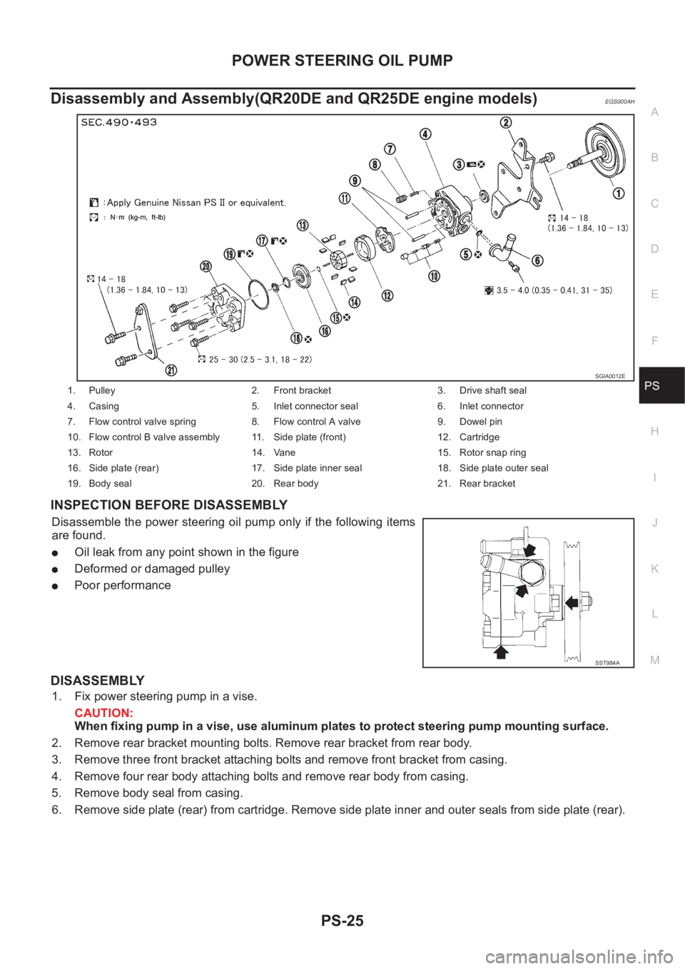
Disassembly and Assembly(QR20DE and QR25DE engine models)EGS000AH
INSPECTION BEFORE DISASSEMBLY
Disassemble the power steering oil pump only if the following items
are found.
●Oil leak from any point shown in the figure
●Deformed or damaged pulley
●Poor performance
DISASSEMBLY
1. Fix power steering pump in a vise.
CAUTION:
When fixing pump in a vise, use aluminum plates to protect steering pump mounting surface.
2. Remove rear bracket mounting bolts. Remove rear bracket from rear body.
3. Remove three front bracket attaching bolts and remove front bracket from casing.
4. Remove four rear body attaching bolts and remove rear body from casing.
5. Remove body seal from casing.
6. Remove side plate (rear) from cartridge. Remove side plate inner and outer seals from side plate (rear).
1. Pulley 2. Front bracket 3. Drive shaft seal
4. Casing 5. Inlet connector seal 6. Inlet connector
7. Flow control valve spring 8. Flow control A valve 9. Dowel pin
10. Flow control B valve assembly 11. Side plate (front) 12. Cartridge
13. Rotor 14. Vane 15. Rotor snap ring
16. Side plate (rear) 17. Side plate inner seal 18. Side plate outer seal
19. Body seal 20. Rear body 21. Rear bracket
SGIA0012E
SST984A
Page 2940 of 3833

PS-30
POWER STEERING OIL PUMP
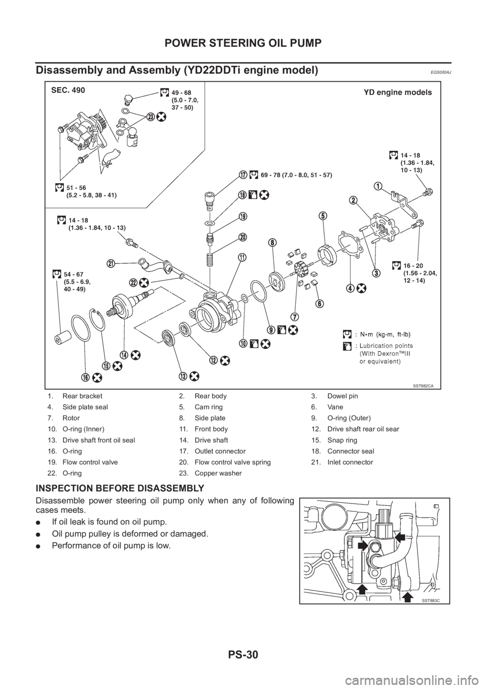
Disassembly and Assembly (YD22DDTi engine model)
EGS000AJ
INSPECTION BEFORE DISASSEMBLY
Disassemble power steering oil pump only when any of following
cases meets.
●If oil leak is found on oil pump.
●Oil pump pulley is deformed or damaged.
●Performance of oil pump is low.
1. Rear bracket 2. Rear body 3. Dowel pin
4. Side plate seal 5. Cam ring 6. Vane
7. Rotor 8. Side plate 9. O-ring (Outer)
10. O-ring (Inner) 11. Front body 12. Drive shaft rear oil sear
13. Drive shaft front oil seal 14. Drive shaft 15. Snap ring
16. O-ring 17. Outlet connector 18. Connector seal
19. Flow control valve 20. Flow control valve spring 21. Inlet connector
22. O-ring 23. Copper washer
SST882CA
SST883C
Page 2992 of 3833

SB-10
SEAT BELT WARNING SYSTEM
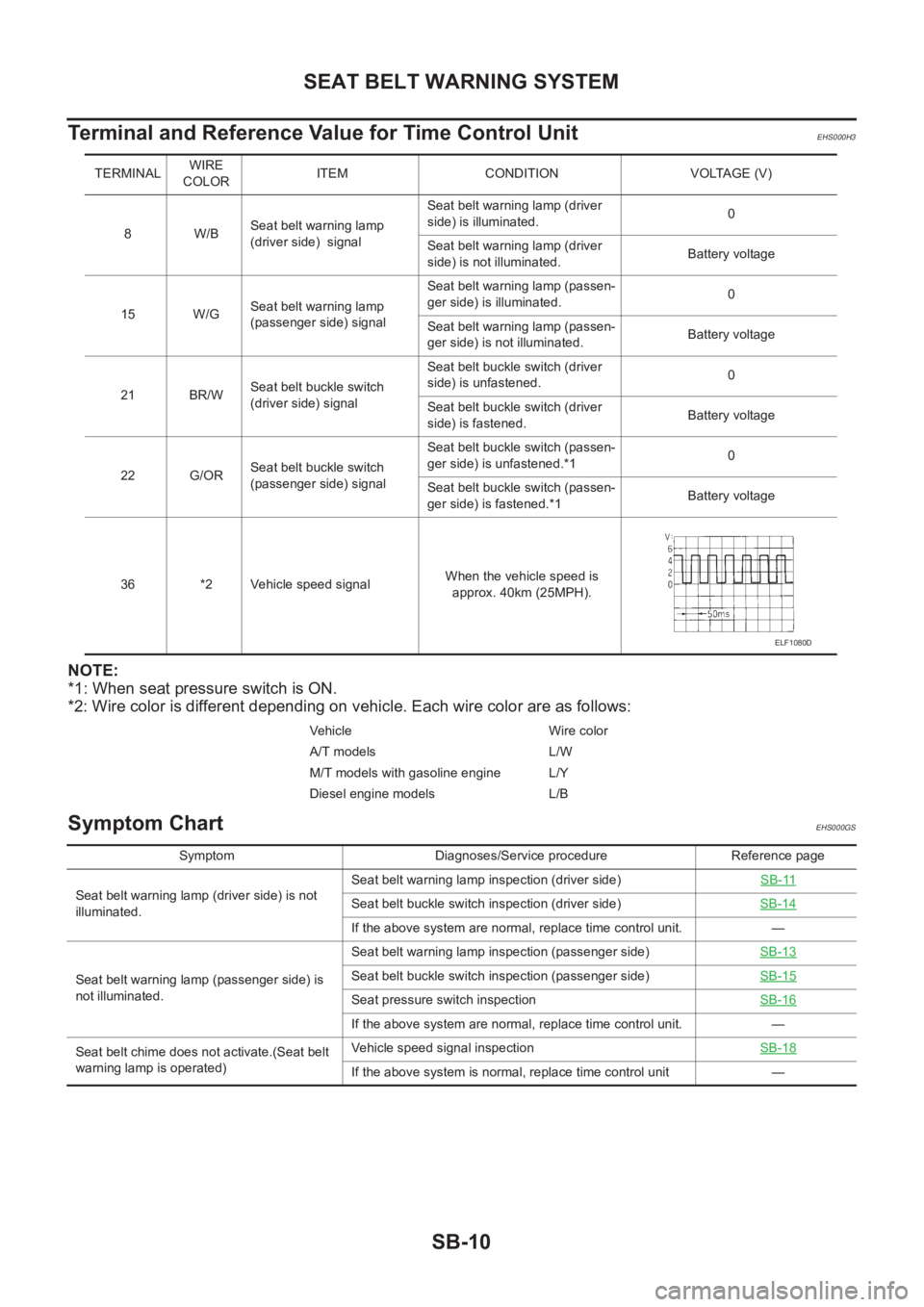
Terminal and Reference Value for Time Control Unit
EHS000H3
NOTE:
*1: When seat pressure switch is ON.
*2: Wire color is different depending on vehicle. Each wire color are as follows:
Symptom ChartEHS000GS
TERMINALWIRE
COLORITEM CONDITION VOLTAGE (V)
8W/BSeat belt warning lamp
(driver side) signalSeat belt warning lamp (driver
side) is illuminated.0
Seat belt warning lamp (driver
side) is not illuminated.Battery voltage
15 W/GSeat belt warning lamp
(passenger side) signalSeat belt warning lamp (passen-
ger side) is illuminated.0
Seat belt warning lamp (passen-
ger side) is not illuminated.Battery voltage
21 BR/WSeat belt buckle switch
(driver side) signalSeat belt buckle switch (driver
side) is unfastened.0
Seat belt buckle switch (driver
side) is fastened.Battery voltage
22 G/ORSeat belt buckle switch
(passenger side) signalSeat belt buckle switch (passen-
ger side) is unfastened.*10
Seat belt buckle switch (passen-
ger side) is fastened.*1Battery voltage
36 *2 Vehicle speed signal When the vehicle speed is
approx. 40km (25MPH).
Vehicle Wire color
A/T models L/W
M/T models with gasoline engine L/Y
Diesel engine models L/B
ELF1080D
Symptom Diagnoses/Service procedure Reference page
Seat belt warning lamp (driver side) is not
illuminated.Seat belt warning lamp inspection (driver side)SB-11
Seat belt buckle switch inspection (driver side)SB-14
If the above system are normal, replace time control unit. —
Seat belt warning lamp (passenger side) is
not illuminated.Seat belt warning lamp inspection (passenger side)SB-13
Seat belt buckle switch inspection (passenger side)SB-15
Seat pressure switch inspectionSB-16
If the above system are normal, replace time control unit. —
Seat belt chime does not activate.(Seat belt
warning lamp is operated)Vehicle speed signal inspectionSB-18
If the above system is normal, replace time control unit —