2001 NISSAN X-TRAIL clutch
[x] Cancel search: clutchPage 2667 of 3833
TROUBLE DIAGNOSIS
TF-57
C
E
F
G
H
I
J
K
L
MA
B
TF
3.INSPECTION USING 4WD MODE CHANGE-OVER SWITCH
●On data monitor screen of the CONSULT-II, check 4WD mode switch.
●Check if the display changes from ## to 2WD mode when the 2WD switch is pressed.
●Check if the display changes from ## to AUTO mode when the AUTO switch is pressed.
●Check if the display changes from ## to LOCK mode when the LOCK switch is pressed.
OK or NG
OK >> No malfunction detected.
NG >>
●Not in AUTO mode. (In 2WD or LOCK mode)
Countermeasure: Slightly depress the accelerator pedal and check that the operation mode
changes to LOCK mode.
●Check circuit between 4WD mode switch harness connector M39 terminal No.1 (BR) and
4WD control unit harness connector E122 terminal No. 27 (BR).
(AUTO mode is not available because a malfunction is present in the 2WD mode harness.)
NOTICE:
Mechanism of 4WD mode change-over.
●2WD mode: Operation changes to 2WD mode when 4WD control unit harness connector E122
terminal No. 27 (BR) is shorted to ground.
●AUTO mode: Operation changes to AUTO mode when 4WD control unit harness connector
E122 terminals No. 27 (BR) and No. 26 (L) is shorted to ground.
●LOCK mode: Operation changes to LOCK mode when 4WD control unit harness connector
E122 terminal No. 26 (L) is shorted to ground.
4WD MODES CANNOT BE SWITCHED AFTER ENGINE IS STARTED
1.INSPECTION USING 4WD MODE CHANGE-OVER SWITCH
●Drive modes cannot be switched after the engine is started.
●On data monitor screen of the CONSULT-II, check 4WD mode switch.
●Check if the display changes from ## to 2WD mode when the 2WD switch is pressed.
●Check if the display changes from ## to AUTO mode when the AUTO switch is pressed.
●Check if the display changes from ## to LOCK mode when the LOCK switch is pressed.
OK or NG
OK >> No malfunction detected.
NG >>
●CONSULT-II display does not change from ## when the 2WD switch is pressed. Check harness
of the 2WD switch.
●CONSULT-II display does not change from ## when the AUTO switch is pressed. Check har-
ness of the 2WD switch and LOCK switch.
●CONSULT-II display does not change from ## when the LOCK switch is pressed. Check har-
ness of the LOCK switch.
●Perform 4WD mode change-over switch inspection.
WHILE DRIVING, 4WD WARNING LAMP FLASHES RAPIDLY. (WHEN IT FLASHERS FOR
APPROX. ONE MINUTE, THEN DOES NOT ILLUMINATE.)
●While driving, 4WD warning lamp flashes rapidly. (when it flashes for approx. one minute, then does not
illuminate.)
Rapid flashing: 2 times/second
This phenomenon protects drivetrain parts when a heavy load is applied to the electronically controlled
coupling and multiple disc clutch temperature increases. It is not a malfunction.
When the difference of diameters by or with the front and rear wheel with AUTO mode the shift switch
occasionally changes to LOCK mode automatically. This is not a malfunction.
When the difference of revolution speed between the front and rear wheel with AUTO mode, the shift
switch occasionally changes to LOCK mode automatically. This is not a malfunction.
WHILE DRIVING, 4WD WARNING LAMP FLASHES SLOWLY. (WHEN IT CONTINUES TO ILLU-
MINATE UNTIL ENGINE TURNS OFF.)
1. Check using the data monitor function of the CONSULT-II.
Page 2803 of 3833
![NISSAN X-TRAIL 2001 Service Repair Manual TROUBLE DIAGNOSIS
BRC-19
[4WD/ABS]
C
D
E
G
H
I
J
K
L
MA
B
BRC
CAUTION:
1. Light tight-corner braking symptom may occur depending on driving conditions in AUTO mode.
This is not malfunction NISSAN X-TRAIL 2001 Service Repair Manual TROUBLE DIAGNOSIS
BRC-19
[4WD/ABS]
C
D
E
G
H
I
J
K
L
MA
B
BRC
CAUTION:
1. Light tight-corner braking symptom may occur depending on driving conditions in AUTO mode.
This is not malfunction](/manual-img/5/57405/w960_57405-2802.png)
TROUBLE DIAGNOSIS
BRC-19
[4WD/ABS]
C
D
E
G
H
I
J
K
L
MA
B
BRC
CAUTION:
1. Light tight-corner braking symptom may occur depending on driving conditions in AUTO mode.
This is not malfunction.
2. Heavy tight-corner braking symptom occurs when vehicle is driven in the following conditions:
LOCK mode, steering wheel is turned fully to either sides, and accelerator pedal was depressed.
4WD/ABS Control Unit Input/Output Signal StandardEFS001BG
4WD/ABS CONTROL UNIT CONNECTOR TERMINAL ARRANGEMENT
CAUTION:
When ignition switch is turned to ON with connectors of 4WD/ABS control unit and actuator con-
nected.
REFERENCE STANDARD TABLE
Specifications defined by circuit tester
Vehicle running, 4WD warning lamp
flashes slowly. (When it flashes for
Approx. One minute, then does not illu-
minate.) slow flashing: One flashing
per 2 seconds●Engine run-
ning
●Driving at
vehicle speed
30km/h (19
MPH)Tire size is different for front and rear of vehicle.BRC-45
Vehicle does not enter 4WD mode
even though 4WD warning lamp is off.Engine runningMechanical malfunction of electronically con-
trolled coupling (Mechanical engagement of
clutch is not possible.)BRC-46
Symptom Condition Check items Reference page
SFIA0351E
Te r m i n a l N o .
Location Standard (note 1)(Note) Check
points when result
was malfunctioning +–
3.
109Power supply Ignition switch ONB a t t e ry v o lta g e ( A p p ro x .
12V)Control unit power
supply circuit
Page 2825 of 3833
![NISSAN X-TRAIL 2001 Service Repair Manual TROUBLE DIAGNOSIS
BRC-41
[4WD/ABS]
C
D
E
G
H
I
J
K
L
MA
B
BRC
4WD MODES CANNOT BE SWITCHED AFTER ENGINE IS STARTED
1.INSPECTION USING 4WD MODE CHANGE-OVER SWITCH
●Drive modes cannot be switched afte NISSAN X-TRAIL 2001 Service Repair Manual TROUBLE DIAGNOSIS
BRC-41
[4WD/ABS]
C
D
E
G
H
I
J
K
L
MA
B
BRC
4WD MODES CANNOT BE SWITCHED AFTER ENGINE IS STARTED
1.INSPECTION USING 4WD MODE CHANGE-OVER SWITCH
●Drive modes cannot be switched afte](/manual-img/5/57405/w960_57405-2824.png)
TROUBLE DIAGNOSIS
BRC-41
[4WD/ABS]
C
D
E
G
H
I
J
K
L
MA
B
BRC
4WD MODES CANNOT BE SWITCHED AFTER ENGINE IS STARTED
1.INSPECTION USING 4WD MODE CHANGE-OVER SWITCH
●Drive modes cannot be switched after the engine is started.
●On data monitor screen of the CONSULT-II, check 4WD mode switch.
●Check if the display changes from ## to 2WD mode when the 2WD switch is pressed.
●Check if the display changes from ## to AUTO mode when the AUTO switch is pressed.
●Check if the display changes from ## to LOCK mode when the LOCK switch is pressed.
OK or NG
OK >> No malfunction detected.
NG >>
●CONSULT-II display does not change from ## when the 2WD switch is pressed. Check harness
of the 2WD switch.
●CONSULT-II display does not change from ## when the AUTO switch is pressed. Check har-
ness of the 2WD switch and LOCK switch.
●CONSULT-II display does not change from ## when the LOCK switch is pressed. Check har-
ness of the LOCK switch.
●Perform 4WD mode change-over switch inspection.
WHILE DRIVING, 4WD WARNING LAMP FLASHES RAPIDLY. (WHEN IT FLASHERS FOR
APPROX. ONE MINUTE, THEN DOES NOT ILLUMINATE.)
●While driving, 4WD warning lamp flashes rapidly. (When it flashes for Approx. One minute, then does not
illuminate.)
Rapid flashing: 2 times/second
This phenomenon protects drivetrain parts when a heavy load is applied to the electronically controlled
coupling and multiple disc clutch temperature increases. It is not a malfunction.
When the difference of revolution speed by or with the front and rear wheel with AUTO mode, the shift
switch occasionally changes to LOCK mode automatically. This is not a malfunction.
When the difference of revolution speed between the front and rear wheel with AUTO mode, the shift
switch occasionally changes to LOCK mode automatically. This is not a malfunction.
WHILE DRIVING, 4WD WARNING LAMP FLASHES SLOWLY. (WHEN IT CONTINUES TO ILLU-
MINATE UNTIL ENGINE TURNS OFF.)
1. Check using the data monitor function of the CONSULT-II.
●Perform inspection with the data monitor function of the CONSULT-II.
●Check if the value of IMPROPER SIZE TIRE MONITOR is 8 mm (0.31 in) or more.
●Stop the engine. Restart the engine and drive the vehicle at 20 km/h (12 MPH) or faster for approxi-
mately 200 seconds. Confirm the 4WD warning lamp flashes slowly.
(Check if the value of IMPROPER SIZE TIRE MONITOR is 8 mm (0.31 in) or more.)
When the tire size is normal, the value of IMPROPER SIZE TIRE MONITOR will change from 8 mm
(0.31 in) or more to 0 to 4 mm (0 to 0.16 in) (normal condition) after the vehicle is driven 20 km/h (12
MPH) or faster for approximately 5 seconds.
2. Tire inspection
●Inspection of tire pressure
●Wear condition
●Check size of the front and rear tires. (No excessive difference should be observed.) Refer to GI-44,
"Wheels & Tires"
VEHICLE DOES NOT ENTER 4WD MODE EVEN THOUGH 4WD WARNING LAMP IS OFF.
1. Check using the data monitor function of the CONSULT-II.
Perform inspection by the data monitor function of the CONSULT-II.
–Check if the vehicle operation changes to 2WD, AUTO, and LOCK modes.
–Check current supplied to the 4WD solenoid valve in AUTO mode.
2. Check using the active test function of the CONSULT-II.Accelerator pedal not depressed : Approx. 0 A
Accelerator pedal depressed : Approx. 2.8 A
Page 2829 of 3833
![NISSAN X-TRAIL 2001 Service Repair Manual TROUBLE DIAGNOSIS
BRC-45
[4WD/ABS]
C
D
E
G
H
I
J
K
L
MA
B
BRC
3.INSPECTION USING DRIVE MODE CHANGE-OVER SWITCH
●On data monitor screen of the CONSULT, check 4WD mode switch.
●Check if the display NISSAN X-TRAIL 2001 Service Repair Manual TROUBLE DIAGNOSIS
BRC-45
[4WD/ABS]
C
D
E
G
H
I
J
K
L
MA
B
BRC
3.INSPECTION USING DRIVE MODE CHANGE-OVER SWITCH
●On data monitor screen of the CONSULT, check 4WD mode switch.
●Check if the display](/manual-img/5/57405/w960_57405-2828.png)
TROUBLE DIAGNOSIS
BRC-45
[4WD/ABS]
C
D
E
G
H
I
J
K
L
MA
B
BRC
3.INSPECTION USING DRIVE MODE CHANGE-OVER SWITCH
●On data monitor screen of the CONSULT, check 4WD mode switch.
●Check if the display changes from ## to 2WD mode when the 2WD switch is pressed.
●Check if the display changes from ## to AUTO mode when the AUTO switch is pressed.
●Check if the display changes from ## to LOCK mode when the LOCK switch is pressed.
Is inspection result OK?
YES >> No malfunction detected.
NO >>
●Not in AUTO mode. (In 2WD or LOCK mode)
Countermeasure: Slightly depress the accelerator pedal and check that the operation mode
changes to LOCK mode.
●Check path between drive mode switch and 4WD/ABS control unit E122 terminal No.27 (BR).
(AUTO mode is not available because a malfunction is present in the 2WD mode harness.)
NOTICE:
Mechanism of drive mode change-over
●2WD mode: Operation changes to 2WD mode when 4WD/ABS control unit connector terminal
No. 27 is shorted to ground.
●AUTO mode: Operation changes to AUTO mode when 4WD/ABS control unit connector termi-
nals No. 27 and No. 26 were shorted to ground.
●LOCK mode: Operation changes to LOCK mode when 4WD/ABS control unit connector E122
terminal No. 26 (L) is shorted to ground.
Drive Modes Cannot Be Switched After Engine Is Started.EFS001BU
1.INSPECTION USING DRIVE MODE CHANGE-OVER SWITCH
●Drive modes cannot be switched after the engine is started.
●On data monitor screen of the CONSULT, check 4WD mode switch.
●Check if the display changes from ## to 2WD mode when the 2WD switch is pressed.
●Check if the display changes from ## to AUTO mode when the AUTO switch is pressed.
●Check if the display changes from ## to LOCK mode when the LOCK switch is pressed.
Is inspection result OK?
YES >> No malfunction detected.
NO >>
●CONSULT-II display does not change from ## when the 2WD switch is pressed. Check harness
of the 2WD switch.
●CONSULT-II display does not change from ## when the AUTO switch is pressed. Check har-
ness of the 2WD switch and LOCK switch.
●CONSULT-II display does not change from ## when the LOCK switch is pressed. Check har-
ness of the LOCK switch.
●Perform drive mode change-over switch inspection.
Wheel Driving, 4WD Warning Lamp Flashes Rapidly. (When It Flashes For
Approx. One Minute, Then Does Not Illuminate.)
EFS001BV
●Wheel driving, 4WD warning lamp flashes rapidly. (When it flashes for Approx. 1 minute, then does not
illuminate.)
Rapid flashing: 2 times/second
This phenomenon protects drivetrain parts when a heavy load is applied to the electronically controlled
coupling and multiple disc clutch temperature increases. It is not a malfunction.
Wheel Driving, 4WD Warning Lamp Flashes Slowly. (When It Continues To Illu-
minate Until Engine Turns OFF.)
EFS001BW
1. Check using the data monitor function of the CONSULT-II.
●Perform inspection with the data monitor function of the CONSULT-II.
●Check if the value of IMPROPER SIZE TIRE MONITOR is 8 mm or more.
Page 3277 of 3833
ATC-1
AUTOMATIC AIR CONDITIONER
J AIR CONDITIONER
CONTENTS
C
D
E
F
G
H
I
K
L
M
SECTION
A
B
AT C
AUTOMATIC AIR CONDITIONER
PRECAUTIONS .......................................................... 4
Precautions for Supplemental Restraint System
(SRS) “AIR BAG” and “SEAT BELT PRE-TEN-
SIONER” .................................................................. 4
Precautions for Working with HFC-134a (R-134a) ..... 4
General Refrigerant Precautions .............................. 5
Lubricant Precautions .............................................. 5
Precautions for Refrigerant Connection ................... 5
FEATURES OF NEW TYPE REFRIGERANT
CONNECTION ...................................................... 6
O-RING AND REFRIGERANT CONNECTION ..... 7
Precautions for Servicing Compressor ..................... 9
Precautions for Service Equipment ........................ 10
RECOVERY/RECYCLING EQUIPMENT ............ 10
ELECTRONIC LEAK DETECTOR ...................... 10
VACUUM PUMP ................................................. 10
MANIFOLD GAUGE SET .................................... 10
SERVICE HOSES ................................................ 11
SERVICE COUPLERS ......................................... 11
REFRIGERANT WEIGHT SCALE ....................... 11
CALIBRATING ACR4 WEIGHT SCALE ............... 11
CHARGING CYLINDER ...................................... 12
Precautions for Leak Detection Dye ....................... 12
IDENTIFICATION ................................................ 12
IDENTIFICATION LABEL FOR VEHICLE ........... 13
Wiring Diagrams and Trouble Diagnosis ................ 13
PREPARATION ......................................................... 14
Special Service Tools ............................................. 14
WITH GASOLINE ENGINE (CWV-615M COM-
PRESSOR) ......................................................... 14
WITH DIESEL ENGINE (DKV-11G COMPRES-
SOR) ................................................................... 14
HFC-134a (R-134a) Service Tools and Equipment ... 15
REFRIGERATION SYSTEM ..................................... 18
Refrigerant Cycle ................................................... 18
REFRIGERANT FLOW ....................................... 18
FREEZE PROTECTION (WITH GASOLINE
ENGINE: CWV-615M COMPRESSOR) .............. 18
Refrigerant System Protection ............................... 18
REFRIGERANT PRESSURE SENSOR (WITH GASOLINE ENGINE: CWV-615M COMPRES-
SOR) ................................................................... 18
DUAL-PRESSURE SWITCH (WITH DIESEL
ENGINE: DKV-11G COMPRESSOR) .................. 18
PRESSURE RELIEF VALVE (WITH GASOLINE
ENGINE: CWV-615M COMPRESSOR) .............. 18
V-6 Variable Displacement Compressor (With Gas-
oline Engine: CWV-615M Compressor) .................. 19
GENERAL INFORMATION ................................. 19
DESCRIPTION .................................................... 20
Component Layout ................................................. 23
LUBRICANT .............................................................. 24
Maintenance of Lubricant Quantity in Compressor ... 24
LUBRICANT ........................................................ 24
LUBRICANT RETURN OPERATION .................. 24
LUBRICANT ADJUSTING PROCEDURE FOR
COMPONENTS REPLACEMENT EXCEPT
COMPRESSOR .................................................. 25
LUBRICANT ADJUSTING PROCEDURE FOR
COMPRESSOR REPLACEMENT ....................... 25
AIR CONDITIONER CONTROL ............................... 27
Overview Air Conditioner LAN Control System ...... 27
System Construction .............................................. 27
OPERATION ........................................................ 27
TRANSMISSION DATA AND TRANSMISSION
ORDER ............................................................... 28
AIR MIX DOOR CONTROL (AUTOMATIC TEM-
PERATURE CONTROL) ..................................... 28
FAN SPEED CONTROL ...................................... 29
INTAKE DOOR CONTROL ................................. 29
OUTLET DOOR CONTROL ................................ 29
MAGNET CLUTCH CONTROL ........................... 29
SELF-DIAGNOSTIC SYSTEM ............................ 29
Overview of Control system .................................... 29
Control Operation ................................................... 30
DISPLAY SCREEN .............................................. 30
AUTO SWITCH ................................................... 30
TEMPERATURE DIAL (POTENTIO TEMPERA-
TURE CONTROL) ............................................... 30
A/C SWITCH ....................................................... 30
Page 3278 of 3833
ATC-2
DEFROSTER (DEF) SWITCH ............................. 30
MODE SWITCH ................................................... 30
FAN SWITCH ...................................................... 30
OFF SWITCH ...................................................... 30
FRESH (FRE) SWITCH ....................................... 30
RECIRCULATION (REC) SWITCH ..................... 30
Discharge Air Flow ................................................. 31
System Description ................................................. 32
SWITCHES AND THEIR CONTROL FUNCTION ... 32
TROUBLE DIAGNOSIS ............................................ 33
How to Perform Trouble Diagnoses for Quick and
Accurate Repair ...................................................... 33
WORK FLOW ...................................................... 33
SYMPTOM TABLE .............................................. 33
Component Parts and Harness Connector Location ... 34
ENGINE COMPARTMENT .................................. 34
PASSENGER COMPARTMENT .......................... 35
Circuit Diagram ....................................................... 36
WITH GASOLINE ENGINE ................................. 36
WITH DIESEL ENGINE ....................................... 37
Wiring Diagram ....................................................... 38
WITH GASOLINE ENGINE ................................. 38
WITH DIESEL ENGINE ....................................... 41
Auto Amp. Terminals and Reference Value ............ 44
PIN CONNECTOR TERMINAL LAYOUT ............ 44
AUTO AMP. INSPECTION TABLE ...................... 44
Self-diagnosis Function .......................................... 46
DESCRIPTION .................................................... 46
PROCEDURE ...................................................... 47
AUXILIARY MECHANISM: TEMPERATURE
SETTING TRIMMER ........................................... 52
AUXILIARY MECHANISM: FOOT POSITION
SETTING TRIMMER ........................................... 53
AUXILIARY MECHANISM: INLET PORT MEM-
ORY FUNCTION (FOR LHD MODELS) .............. 54
Operational Check .................................................. 54
CHECKING MEMORY FUNCTION ..................... 54
CHECKING BLOWER ......................................... 55
CHECKING DISCHARGE AIR ............................ 55
CHECKING RECIRCULATION ............................ 55
CHECKING TEMPERATURE DECREASE ......... 56
CHECKING TEMPERATURE INCREASE .......... 56
CHECKING AUTO MODE ................................... 56
Power Supply and Ground Circuit for Auto Amp. ... 57
INSPECTION FLOW ........................................... 57
COMPONENT DESCRIPTION ............................ 57
DIAGNOSTIC PROCEDURE .............................. 58
LAN System Circuit ............................................. ... 59
DIAGNOSTIC PROCEDURE .............................. 59
Mode Door Motor Circuit ........................................ 62
INSPECTION FLOW ........................................
... 62
SYSTEM DESCRIPTION .................................... 63
COMPONENT DESCRIPTION ............................ 64
DIAGNOSTIC PROCEDURE .............................. 64
Air Mix Door Motor Circuit ...................................... 64
INSPECTION FLOW ........................................... 65
SYSTEM DESCRIPTION .................................... 66
COMPONENT DESCRIPTION ............................ 66
DIAGNOSTIC PROCEDURE .............................. 67Intake Door Motor Circuit ........................................ 68
INSPECTION FLOW ............................................ 68
SYSTEM DESCRIPTION ..................................... 69
COMPONENT DESCRIPTION ............................ 69
DIAGNOSTIC PROCEDURE ............................... 70
Blower Motor Circuit ................................................ 70
INSPECTION FLOW ............................................ 71
SYSTEM DESCRIPTION ..................................... 72
COMPONENT DESCRIPTION ............................ 74
DIAGNOSTIC PROCEDURE ............................... 74
COMPONENT INSPECTION ............................... 77
Magnet Clutch Circuit .............................................. 78
INSPECTION FLOW ............................................ 78
SYSTEM DESCRIPTION ..................................... 79
DIAGNOSTIC PROCEDURE ............................... 79
COMPONENT INSPECTION ............................... 84
Insufficient Cooling .................................................. 86
INSPECTION FLOW ............................................ 86
PERFORMANCE TEST DIAGNOSES ................ 88
PERFORMANCE CHART .................................... 90
TROUBLE DIAGNOSES FOR UNUSUAL PRES-
SURE ................................................................... 92
Insufficient Heating ................................................. 95
INSPECTION FLOW ............................................ 95
Noise ....................................................................... 97
INSPECTION FLOW ............................................ 97
Self-diagnosis ......................................................... 98
INSPECTION FLOW ............................................ 98
Memory Function .................................................... 99
INSPECTION FLOW ............................................ 99
Ambient Sensor Circuit .........................................100
COMPONENT DESCRIPTION ..........................100
AMBIENT TEMPERATURE INPUT PROCESS .100
DIAGNOSTIC PROCEDURE .............................100
COMPONENT INSPECTION .............................102
In-vehicle Sensor Circuit .......................................102
COMPONENT DESCRIPTION ..........................102
DIAGNOSTIC PROCEDURE .............................103
COMPONENT INSPECTION .............................104
Sunload Sensor Circuit .........................................105
COMPONENT DESCRIPTION ..........................105
SUNLOAD INPUT PROCESS ...........................105
DIAGNOSTIC PROCEDURE .............................105
COMPONENT INSPECTION .............................107
Intake Sensor Circuit .............................................108
COMPONENT DESCRIPTION ..........................108
DIAGNOSTIC PROCEDURE .............................108
CONTROLLER ........................................................ 111
Removal and Installation .......................................111
Disassembly and Assembly ..................................111
AMBIENT SENSOR ................................................112
Removal and Installation .......................................112
IN-VEHICLE SENSOR ............................................113
Removal and Installation .......................................113
SUNLOAD SENSOR ...............................................114
Removal and Installation .......................................114
INTAKE SENSOR CIRCUIT ....................................115
Removal and Installation .......................................115
BLOWER UNIT ........................................................116
Page 3279 of 3833
ATC-3
C
D
E
F
G
H
I
K
L
MA
B
AT C Removal and Installation ....................................... 116
REMOVAL .......................................................... 116
INSTALLATION .................................................. 116
Disassembly and Assembly .................................. 117
BLOWER MOTOR ...................................................118
Removal and Installation ....................................... 118
INTAKE DOOR MOTOR ..........................................119
Removal and Installation ....................................... 119
FAN CONTROL AMPLIFIER .................................. 120
Removal and Installation ...................................... 120
VENTILATION AIR FILTER .................................... 121
Removal and Installation ...................................... 121
FUNCTION ........................................................ 121
REPLACEMENT TIMING .................................. 121
REPLACEMENT AND PROCEDURES ............ 121
CLEANING ....................................................... . 121
HEATER & COOLING UNIT ASSEMBLY .............. 122
Removal and Installation ...................................... 122
REMOVAL ......................................................... 122
INSTALLATION ................................................. 123
Disassembly and Assembly ................................. 123
MODE DOOR MOTOR ........................................... 124
Removal and Installation ...................................... 124
AIR MIX DOOR MOTOR ......................................... 125
Removal and Installation ...................................... 125
HEATER CORE ...................................................... 126
Removal and Installation ...................................... 126
DUCTS AND GRILLES .......................................... 127
Removal and Installation ...................................... 127
VENTILATOR DUCT, DEFROSTER NOZZLE
AND DEFROSTER DUCTS .............................. 127
CENTER VENTILATOR GRILLE ...................... 127
SIDE VENTILATOR GRILLE ............................. 127
FOOT DUCT ..................................................... 128
FLOOR DUCT ................................................... 128
REFRIGERANT LINES ........................................... 129
HFC-134a (R-134a) Service Procedure ............... 129
SETTING OF SERVICE TOOLS AND EQUIP-
MENT ................................................................ 129
Components ......................................................... 131
WITH GASOLINE ENGINE ............................... 131
WITH DIESEL ENGINE .................................... 132
Removal and Installation for Compressor ............ 132REMOVAL .........................................................132
INSTALLATION .................................................134
Removal and Installation for Compressor Clutch . 135
REMOVAL .........................................................135
INSTALLATION .................................................138
Removal and Installation for Low-pressure flexible
hose ......................................................................141
REMOVAL .........................................................141
INSTALLATION .................................................141
Removal and Installation for High-pressure flexible
hose ......................................................................142
REMOVAL .........................................................142
INSTALLATION .................................................142
Removal and Installation for High-pressure pipe ..142
REMOVAL .........................................................142
INSTALLATION .................................................142
Removal and Installation for Refrigerant Pressure
Sensor ..................................................................143
Removal and Installation for Dual-pressure Switch .143
Removal and Installation for Condenser ..............143
REMOVAL .........................................................143
INSTALLATION .................................................144
Removal and Installation for Evaporator ..............145
REMOVAL .........................................................145
INSTALLATION .................................................145
Removal and Installation for Expansion Valve ......146
Removal and Installation for Liquid Tank ..............146
REMOVAL .........................................................146
INSTALLATION .................................................146
Checking for Refrigerant Leaks ............................146
Checking System for Leaks Using the Fluorescent
Leak Detector .......................................................147
Dye Injection .........................................................147
Electronic Refrigerant Leak Detector ....................147
PRECAUTIONS FOR HANDLING LEAK
DETECTOR .......................................................147
CHECKING PROCEDURE ...............................148
SERVICE DATA AND SPECIFICATIONS (SDS) ....150
COMPRESSOR ....................................................150
LUBRICANT .........................................................150
REFRIGERANT ....................................................150
ENGINE IDLING SPEED ......................................150
BELT TENSION ................................................... .150
Page 3285 of 3833
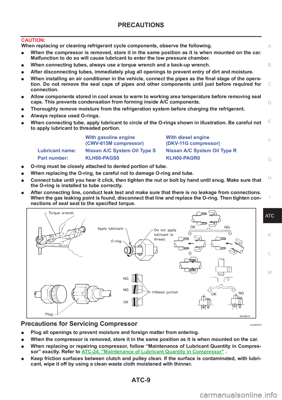
PRECAUTIONS
ATC-9
C
D
E
F
G
H
I
K
L
MA
B
AT C
CAUTION:
When replacing or cleaning refrigerant cycle components, observe the following.
●When the compressor is removed, store it in the same position as it is when mounted on the car.
Malfunction to do so will cause lubricant to enter the low pressure chamber.
●When connecting tubes, always use a torque wrench and a back-up wrench.
●After disconnecting tubes, immediately plug all openings to prevent entry of dirt and moisture.
●When installing an air conditioner in the vehicle, connect the pipes as the final stage of the opera-
tion. Do not remove the seal caps of pipes and other components until just before required for
connection.
●Allow components stored in cool areas to warm to working area temperature before removing seal
caps. This prevents condensation from forming inside A/C components.
●Thoroughly remove moisture from the refrigeration system before charging the refrigerant.
●Always replace used O-rings.
●When connecting tube, apply lubricant to circle of the O-rings shown in illustration. Be careful not
to apply lubricant to threaded portion.
●O-ring must be closely attached to dented portion of tube.
●When replacing the O-ring, be careful not to damage O-ring and tube.
●Connect tube until you hear it click, then tighten the nut or bolt by hand until snug. Make sure that
the O-ring is installed to tube correctly.
●After connecting line, conduct leak test and make sure that there is no leakage from connections.
When the gas leaking point is found, disconnect that line and replace the O-ring. Then tighten con-
nections of seal seat to the specified torque.
Precautions for Servicing CompressorEJS000T5
●Plug all openings to prevent moisture and foreign matter from entering.
●When the compressor is removed, store it in the same position as it is when mounted on the car.
●When replacing or repairing compressor, follow “Maintenance of Lubricant Quantity in Compres-
sor” exactly. Refer to ATC-24, "
Maintenance of Lubricant Quantity in Compressor" .
●Keep friction surfaces between clutch and pulley clean. If the surface is contaminated, with lubri-
cant, wipe it off by using a clean waste cloth moistened with thinner. With gasoline engine
(CWV-615M compressor)With diesel engine
(DKV-11G compressor)
Lubricant name: Nissan A/C System Oil Type S Nissan A/C System Oil Type R
Part number: KLH00-PAGS0 KLH00-PAGR0
RHA861F