Page 3413 of 3833

REFRIGERANT LINES
ATC-137
C
D
E
F
G
H
I
K
L
MA
B
AT C
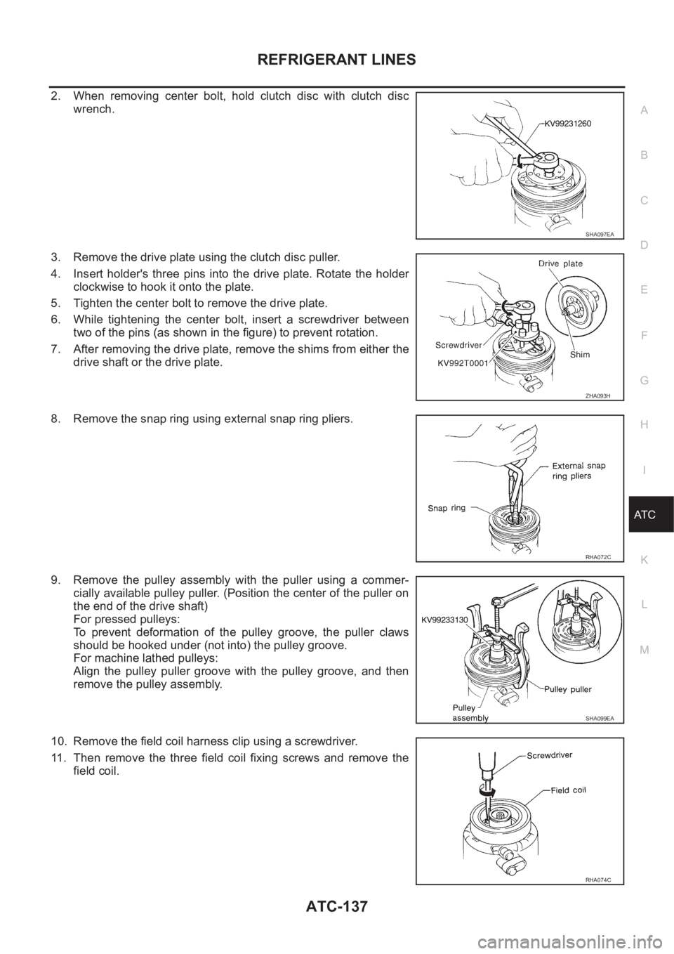
2. When removing center bolt, hold clutch disc with clutch disc
wrench.
3. Remove the drive plate using the clutch disc puller.
4. Insert holder's three pins into the drive plate. Rotate the holder
clockwise to hook it onto the plate.
5. Tighten the center bolt to remove the drive plate.
6. While tightening the center bolt, insert a screwdriver between
two of the pins (as shown in the figure) to prevent rotation.
7. After removing the drive plate, remove the shims from either the
drive shaft or the drive plate.
8. Remove the snap ring using external snap ring pliers.
9. Remove the pulley assembly with the puller using a commer-
cially available pulley puller. (Position the center of the puller on
the end of the drive shaft)
For pressed pulleys:
To prevent deformation of the pulley groove, the puller claws
should be hooked under (not into) the pulley groove.
For machine lathed pulleys:
Align the pulley puller groove with the pulley groove, and then
remove the pulley assembly.
10. Remove the field coil harness clip using a screwdriver.
11. Then remove the three field coil fixing screws and remove the
field coil.
SHA097EA
ZHA093H
RHA072C
SHA099EA
RHA074C
Page 3414 of 3833
ATC-138
REFRIGERANT LINES
Inspection
Clutch disc
If the contact surface shows signs of damage due to excessive heat,
replace clutch disc and pulley.
Pulley
Check the appearance of the pulley assembly. If the contact surface
of pulley sows signs of excessive grooving, replace clutch disc and
pulley. The contact surfaces of the pulley assembly should be
cleaned with a suitable solvent before reinstallation.
Coil
Check coil for loose connection or cracked insulation.
INSTALLATION
With Gasoline Engine (CWV-615M Compressor)
1. Install the field coil.
Be sure to align the coil's pin with the hole in the compressor's
front head.
2. Install the field coil harness clip using a screwdriver.
3. Install the pulley assembly using the installer and a hand press,
and then install the snap ring using snap ring pliers.
RJIA0582E
RJIA0583E
RHA142E
RHA143EA
Page 3415 of 3833
REFRIGERANT LINES
ATC-139
C
D
E
F
G
H
I
K
L
MA
B
AT C
4. Install the clutch disc on the drive shaft, together with the original
shim(s). Press the clutch disc down by hand.
5. Using the holder to prevent clutch disc rotation.
After tightening the bolt, check that the pulley rotates smoothly.
6. Check clearance around the entire periphery of clutch disc.
If the specified clearance is not obtained, replace adjusting
spacer and readjust.
With Diesel Engine (DKV-11G Compressor)
1. Install the field coil.
Be sure to align the coil's pin with the hole in the compressor's
front head.
2. Install the field coil harness clip using a screwdriver.
RHA127F
Tightening torque : 14 N-m (1.4 kg-m, 10 ft-lb)
RHA086E
Disc to pulley clear-
ance: 0.3 - 0.6 mm (0.012 - 0.024 in)
RHA087E
RHA076C
Page 3416 of 3833
ATC-140
REFRIGERANT LINES
3. Install the pulley assembly using the installer and a hand press,
and then install the snap ring using snap ring pliers.
4. Install the drive plate on the drive shaft, together with the original
shim(s). Press the clutch disc down by hand.
5. Using the holder to prevent clutch disc rotation.
After tightening the bolt, check that the pulley rotates smoothly.
6. Check clearance around the entire periphery of clutch disc.
If the specified clearance is not obtained, replace adjusting
spacer and readjust.
ZHA094H
RHA078C
Tightening torque : 12 - 15 N-m (1.2 - 1.5 kg-m, 9
- 10 ft-lb)
SHA101EA
Disc to pulley clear-
ance: 0.2 - 0.5 mm (0.008 - 0.020 in)
RHA080CA
Page 3417 of 3833

REFRIGERANT LINES
ATC-141
C
D
E
F
G
H
I
K
L
MA
B
AT C
Break-In Operation
When replacing compressor clutch assembly, always carry out the break-in operation. This is done by engag-
ing and disengaging the clutch about thirty times. Break-in operation raises the level of transmitted torque.
Removal and Installation for Low-pressure flexible hoseEJS000VB
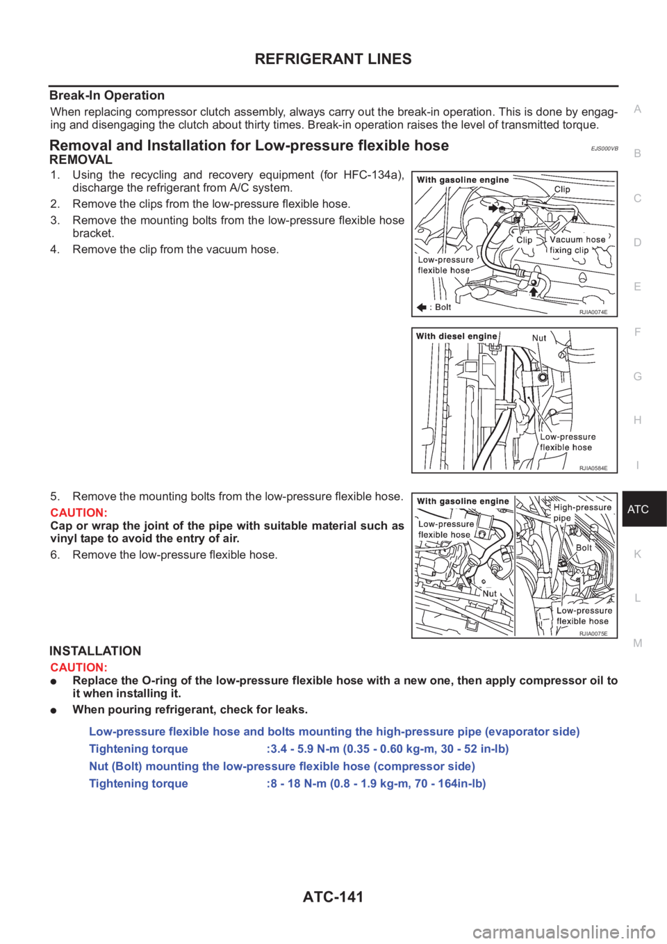
REMOVAL
1. Using the recycling and recovery equipment (for HFC-134a),
discharge the refrigerant from A/C system.
2. Remove the clips from the low-pressure flexible hose.
3. Remove the mounting bolts from the low-pressure flexible hose
bracket.
4. Remove the clip from the vacuum hose.
5. Remove the mounting bolts from the low-pressure flexible hose.
CAUTION:
Cap or wrap the joint of the pipe with suitable material such as
vinyl tape to avoid the entry of air.
6. Remove the low-pressure flexible hose.
INSTALLATION
CAUTION:
●Replace the O-ring of the low-pressure flexible hose with a new one, then apply compressor oil to
it when installing it.
●When pouring refrigerant, check for leaks.
RJIA0074E
RJIA0584E
RJIA0075E
Low-pressure flexible hose and bolts mounting the high-pressure pipe (evaporator side)
Tightening torque :3.4 - 5.9 N-m (0.35 - 0.60 kg-m, 30 - 52 in-lb)
Nut (Bolt) mounting the low-pressure flexible hose (compressor side)
Tightening torque :8 - 18 N-m (0.8 - 1.9 kg-m, 70 - 164in-lb)
Page 3457 of 3833

SC-1
STARTING & CHARGING SYSTEM
K ELECTRICAL
CONTENTS
C
D
E
F
G
H
I
J
L
M
SECTION
A
B
SC
STARTING & CHARGING SYSTEM
PRECAUTIONS .......................................................... 2
Precautions for Supplemental Restraint System
(SRS) “AIR BAG” and “SEAT BELT PRE-TEN-
SIONER” .................................................................. 2
Wiring Diagrams and Trouble Diagnosis .................. 2
BATTERY .................................................................... 3
How to Handle Battery ............................................. 3
METHODS OF PREVENTING OVER-DIS-
CHARGE ............................................................... 3
CHECKING ELECTROLYTE LEVEL .................... 3
SPECIFIC GRAVITY CHECK ............................... 4
Battery Test and Charging Chart .............................. 5
CHART I ................................................................ 5
CHART II ............................................................... 6
A: SLOW CHARGE ............................................... 7
B: STANDARD CHARGE ...................................... 8
C: QUICK CHARGE ............................................ 10
Removal and Installation ......................................... 11
CHARGING SYSTEM ............................................... 12
System Description ................................................ 12
Wiring Diagram — CHARGE — ............................. 13
Trouble Diagnoses ................................................. 14
WITH IC REGULATOR ....................................... 14
MALFUNCTION INDICATOR .............................. 14
Removal and Installation ........................................ 15
REMOVAL (QR ENGINE MODELS) ................... 15
REMOVAL (YD ENGINE MODELS) ................... 15
INSTALLATION ................................................... 15
Disassembly and Assembly ................................... 16
Disassembly ........................................................... 17
REAR COVER .................................................... 17
REAR BEARING ................................................. 18Inspection ............................................................... 18
ROTOR CHECK .................................................. 18
BRUSH CHECK .................................................. 18
PULLEY CHECK(WITH CLUTCH TYPE) ............ 18
STATOR CHECK ................................................. 18
Assembly ................................................................ 19
RING FITTING IN REAR BEARING .................... 19
REAR COVER INSTALLATION ........................... 19
STARTING SYSTEM ................................................. 20
System Description ................................................. 20
M/T MODELS ...................................................... 20
A/T MODELS ....................................................... 20
Wiring Diagram — START —/M/T models ............. 21
Wiring Diagram — START —/A/T models .............. 22
Trouble Diagnoses ..............................................
... 23
Removal and Installation ........................................ 24
REMOVAL ........................................................... 24
INSTALLATION ................................................... 24
Disassembly and Assembly .................................... 25
Inspection ............................................................... 28
MAGNETIC SWITCH CHECK ............................. 28
PINION/CLUTCH CHECK ................................... 28
BRUSH CHECK .................................................. 28
YOKE CHECK ..................................................... 29
ARMATURE CHECK ........................................... 30
Assembly ................................................................ 31
PINION PROTRUSION LENGTH ADJUST-
MENT .................................................................. 31
SERVICE DATA AND SPECIFICATIONS (SDS) ...... 33
Battery .................................................................... 33
Starter ..................................................................... 33
Alternator ................................................................ 33
Page 3474 of 3833

SC-18
CHARGING SYSTEM
REAR BEARING
CAUTION:
●Do not reuse rear bearing after removal. Replace with a new one.
●Do not lubricate rear bearing outer race.
InspectionEKS0031D
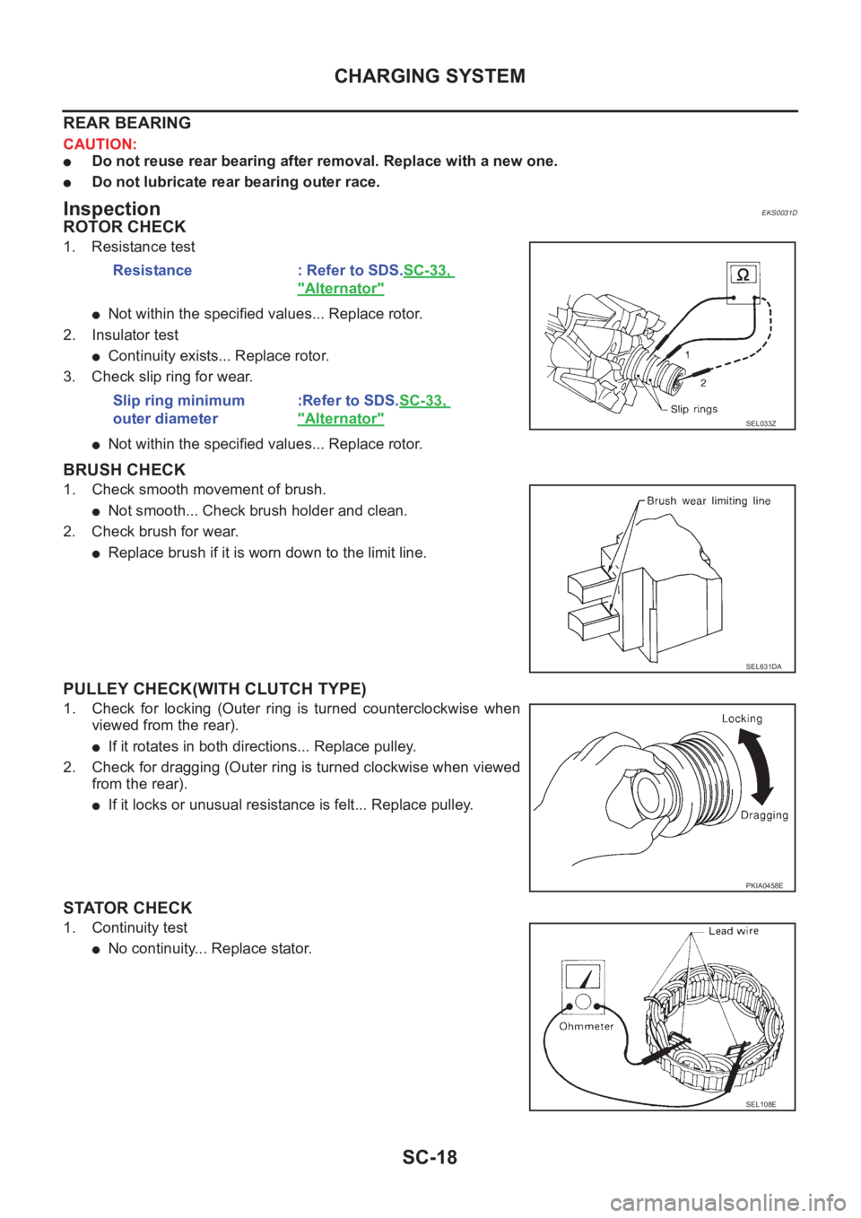
ROTOR CHECK
1. Resistance test
●Not within the specified values... Replace rotor.
2. Insulator test
●Continuity exists... Replace rotor.
3. Check slip ring for wear.
●Not within the specified values... Replace rotor.
BRUSH CHECK
1. Check smooth movement of brush.
●Not smooth... Check brush holder and clean.
2. Check brush for wear.
●Replace brush if it is worn down to the limit line.
PULLEY CHECK(WITH CLUTCH TYPE)
1. Check for locking (Outer ring is turned counterclockwise when
viewed from the rear).
●If it rotates in both directions... Replace pulley.
2. Check for dragging (Outer ring is turned clockwise when viewed
from the rear).
●If it locks or unusual resistance is felt... Replace pulley.
STATOR CHECK
1. Continuity test
●No continuity... Replace stator.Resistance : Refer to SDS.SC-33,
"Alternator"
Slip ring minimum
outer diameter:Refer to SDS.SC-33,
"Alternator"SEL033Z
SEL631DA
PKIA0458E
SEL108E
Page 3482 of 3833
SC-26
STARTING SYSTEM
1. Stopper clip 2. Pinion stopper 3. Pinion
4. Spring 5. Gear case 6. Plate
7. Packing 8. Adjusting plate 9. Magnetic switch assembly
10. Snap ring 11. Retainer ring 12. Over running clutch
13. Internal gear 14. Planetary gear 15. Ball
16. Packing 17. Cover 18. Yoke
19. Armature 20. Washer 21. Rear bearing
22. Brush holder assembly 23. Brush spring 24. Brush(-)
25. Rear cover
Through-bolt :
: 5.6 - 10.4N·m (0.57 - 1.06kg-m, 49.5 - 92.0 in-lb)
PKIA0465E