Page 3286 of 3833
ATC-10
PRECAUTIONS
●After compressor service operation, turn the compressor shaft by hand more than five turns in
both directions. This will equally distribute lubricant inside the compressor. After the compressor
is installed, let the engine idle and operate the compressor for one hour.
●After replacing the compressor magnet clutch, apply voltage to the new one and check for normal
operation.
Precautions for Service EquipmentEJS000T6
RECOVERY/RECYCLING EQUIPMENT
Be certain to follow the manufacturers instructions for machine operation and machine maintenance. Never
introduce any refrigerant other than that specified into the machine.
ELECTRONIC LEAK DETECTOR
Be certain to follow the manufacturer's instructions for tester operation and tester maintenance.
VACUUM PUMP
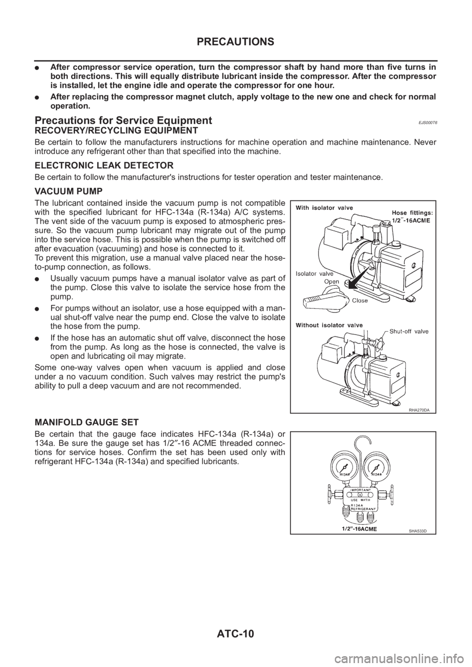
The lubricant contained inside the vacuum pump is not compatible
with the specified lubricant for HFC-134a (R-134a) A/C systems.
The vent side of the vacuum pump is exposed to atmospheric pres-
sure. So the vacuum pump lubricant may migrate out of the pump
into the service hose. This is possible when the pump is switched off
after evacuation (vacuuming) and hose is connected to it.
To prevent this migration, use a manual valve placed near the hose-
to-pump connection, as follows.
●Usually vacuum pumps have a manual isolator valve as part of
the pump. Close this valve to isolate the service hose from the
pump.
●For pumps without an isolator, use a hose equipped with a man-
ual shut-off valve near the pump end. Close the valve to isolate
the hose from the pump.
●If the hose has an automatic shut off valve, disconnect the hose
from the pump. As long as the hose is connected, the valve is
open and lubricating oil may migrate.
Some one-way valves open when vacuum is applied and close
under a no vacuum condition. Such valves may restrict the pump's
ability to pull a deep vacuum and are not recommended.
MANIFOLD GAUGE SET
Be certain that the gauge face indicates HFC-134a (R-134a) or
134a. Be sure the gauge set has 1/2″-16 ACME threaded connec-
tions for service hoses. Confirm the set has been used only with
refrigerant HFC-134a (R-134a) and specified lubricants.
RHA270DA
SHA533D
Page 3290 of 3833
ATC-14
PREPARATION
PREPARATION
PFP:00002
Special Service ToolsEJS001F1
WITH GASOLINE ENGINE (CWV-615M COMPRESSOR)
WITH DIESEL ENGINE (DKV-11G COMPRESSOR)
Tool number
Tool nameDescription
KV99106100
Clutch disc wrenchRemoving shaft nut and clutch disc
KV99232340
or
KV992T0001
Clutch disc pullerRemoving clutch disc
KV99106200
Pulley installerInstalling pulley
S-NT232
RJIA0194E
S-NT376
S-NT235
Tool number
Tool nameDescription
KV99231260
Clutch disc wrenchRemoving shaft nut and clutch disc
KV992T0001
Clutch disc pullerRemoving clutch disc
RJIA0475E
RJIA0476E
Page 3295 of 3833
REFRIGERATION SYSTEM
ATC-19
C
D
E
F
G
H
I
K
L
MA
B
AT C
V-6 Variable Displacement Compressor (With Gasoline Engine: CWV-615M
Compressor)
EJS000TF
GENERAL INFORMATION
1. The V-6 variable compressor differs from previous units. The vent temperatures of the V-6 variable com-
pressor do not drop too far below 5°C (41°F) when:
Evaporator intake air temperature is less than 20°C (68°F).
Engine is running at speeds less than 1,500 rpm.
This is because the V-6 compressor provides a means of "capacity" control.
2. The V-6 variable compressor provides refrigerant control under varying conditions. During cold winters, it
may not produce high refrigerant pressure discharge (compared to previous units) when used with air
conditioning systems.
3. A "clanking" sound may occasionally be heard during refrigerant charge. The sound indicates that the tilt
angle of the swash plate has changed and is not a problem.
4. For air conditioning systems with the V-6 compressor, the clutch remains engaged unless: the system
main switch, fan switch or ignition switch is turned OFF. When ambient (outside) temperatures are low or
when the amount of refrigerant is insufficient, the clutch is disengaged to protect the compressor.
5. A constant range of suction pressure is maintained when engine speed is greater than a certain value. It
normally ranges from 147 to 177 kPa (1.5 to 1.8 kg/cm
2 , 21 to 26 psi) under varying conditions.
In previous compressors, however, suction pressure was reduced with increases in engine speed.
Page 3305 of 3833
AIR CONDITIONER CONTROL
ATC-29
C
D
E
F
G
H
I
K
L
MA
B
AT C
FAN SPEED CONTROL
Blower speed is automatically controlled based on temperature setting, ambient temperature, in-vehicle tem-
perature, intake temperature, amount of sunload and air mix door position.
With FAN switch set to AUTO, the blower motor starts to gradually increase air flow volume.
When engine coolant temperature is low, the blower motor operation is delayed to prevent cool air from flow-
ing.
INTAKE DOOR CONTROL
The intake doors are automatically controlled by: The temperature setting, ambient temperature, in-vehicle
temperature, intake temperature, amount of sunload and ON-OFF operation of the compressor.
OUTLET DOOR CONTROL
The outlet door is automatically controlled by: The temperature setting, ambient temperature, in-vehicle tem-
perature, intake temperature and amount of sunload.
MAGNET CLUTCH CONTROL
The ECM controls compressor operation using input signals from the throttle position sensor and auto ampli-
fier.
SELF-DIAGNOSTIC SYSTEM
The self-diagnostic system is built into the auto amplifier (LCU) to quickly locate the cause of malfunctions.
Overview of Control systemEJS000TK
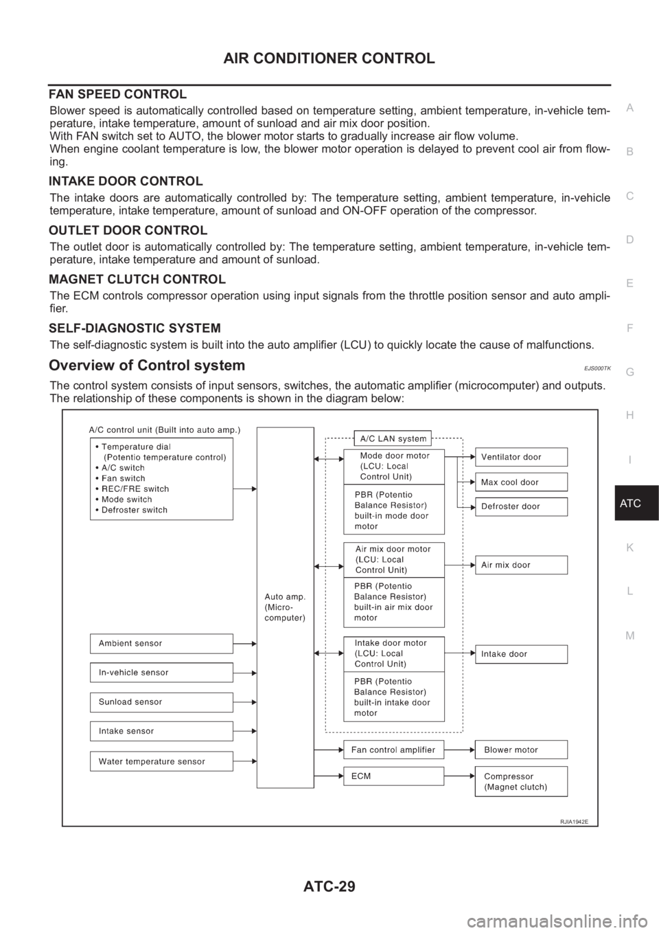
The control system consists of input sensors, switches, the automatic amplifier (microcomputer) and outputs.
The relationship of these components is shown in the diagram below:
RJIA1942E
Page 3309 of 3833
TROUBLE DIAGNOSIS
ATC-33
C
D
E
F
G
H
I
K
L
MA
B
AT C
TROUBLE DIAGNOSISPFP:00004
How to Perform Trouble Diagnoses for Quick and Accurate RepairEJS001GS
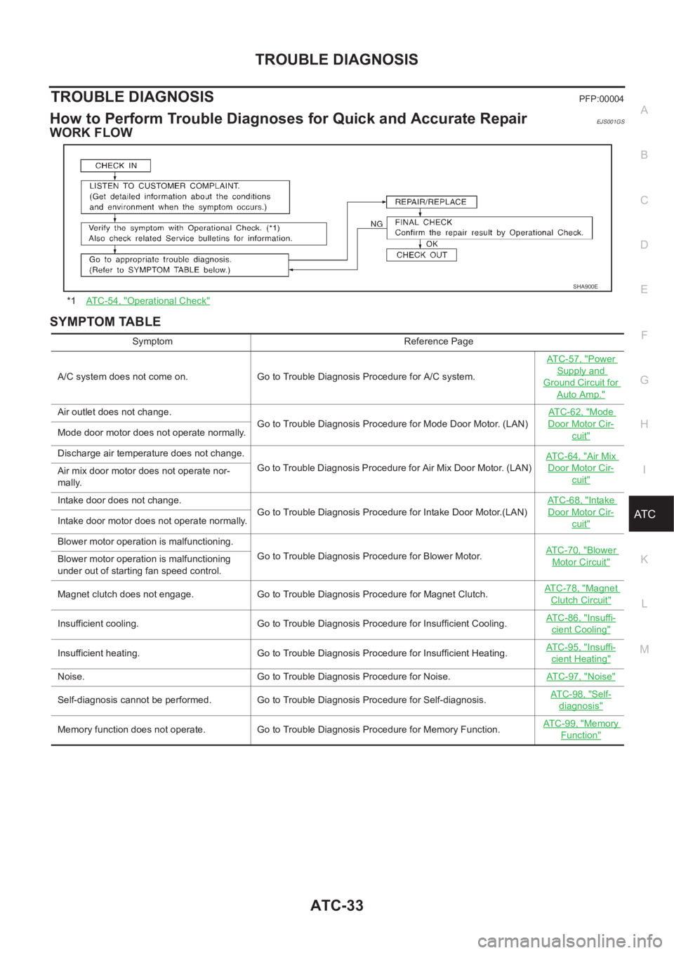
WORK FLOW
SYMPTOM TABLE
*1AT C - 5 4 , "Operational Check"
SHA900E
Symptom Reference Page
A/C system does not come on. Go to Trouble Diagnosis Procedure for A/C system.ATC-57, "
Power
Supply and
Ground Circuit for
Auto Amp."
Air outlet does not change.
Go to Trouble Diagnosis Procedure for Mode Door Motor. (LAN)AT C - 6 2 , "Mode
Door Motor Cir-
cuit"Mode door motor does not operate normally.
Discharge air temperature does not change.
Go to Trouble Diagnosis Procedure for Air Mix Door Motor. (LAN)ATC-64, "
Air Mix
Door Motor Cir-
cuit"Air mix door motor does not operate nor-
mally.
Intake door does not change.
Go to Trouble Diagnosis Procedure for Intake Door Motor.(LAN)AT C - 6 8 , "
Intake
Door Motor Cir-
cuit"Intake door motor does not operate normally.
Blower motor operation is malfunctioning.
Go to Trouble Diagnosis Procedure for Blower Motor.ATC-70, "
Blower
Motor Circuit"Blower motor operation is malfunctioning
under out of starting fan speed control.
Magnet clutch does not engage. Go to Trouble Diagnosis Procedure for Magnet Clutch.AT C - 7 8 , "
Magnet
Clutch Circuit"
Insufficient cooling. Go to Trouble Diagnosis Procedure for Insufficient Cooling.AT C - 8 6 , "Insuffi-
cient Cooling"
Insufficient heating. Go to Trouble Diagnosis Procedure for Insufficient Heating.AT C - 9 5 , "Insuffi-
cient Heating"
Noise. Go to Trouble Diagnosis Procedure for Noise.ATC-97, "Noise"
Self-diagnosis cannot be performed. Go to Trouble Diagnosis Procedure for Self-diagnosis.AT C - 9 8 , "Self-
diagnosis"
Memory function does not operate. Go to Trouble Diagnosis Procedure for Memory Function.AT C - 9 9 , "Memory
Function"
Page 3325 of 3833
TROUBLE DIAGNOSIS
ATC-49
C
D
E
F
G
H
I
K
L
MA
B
AT C
8.CHECK ACTUATORS
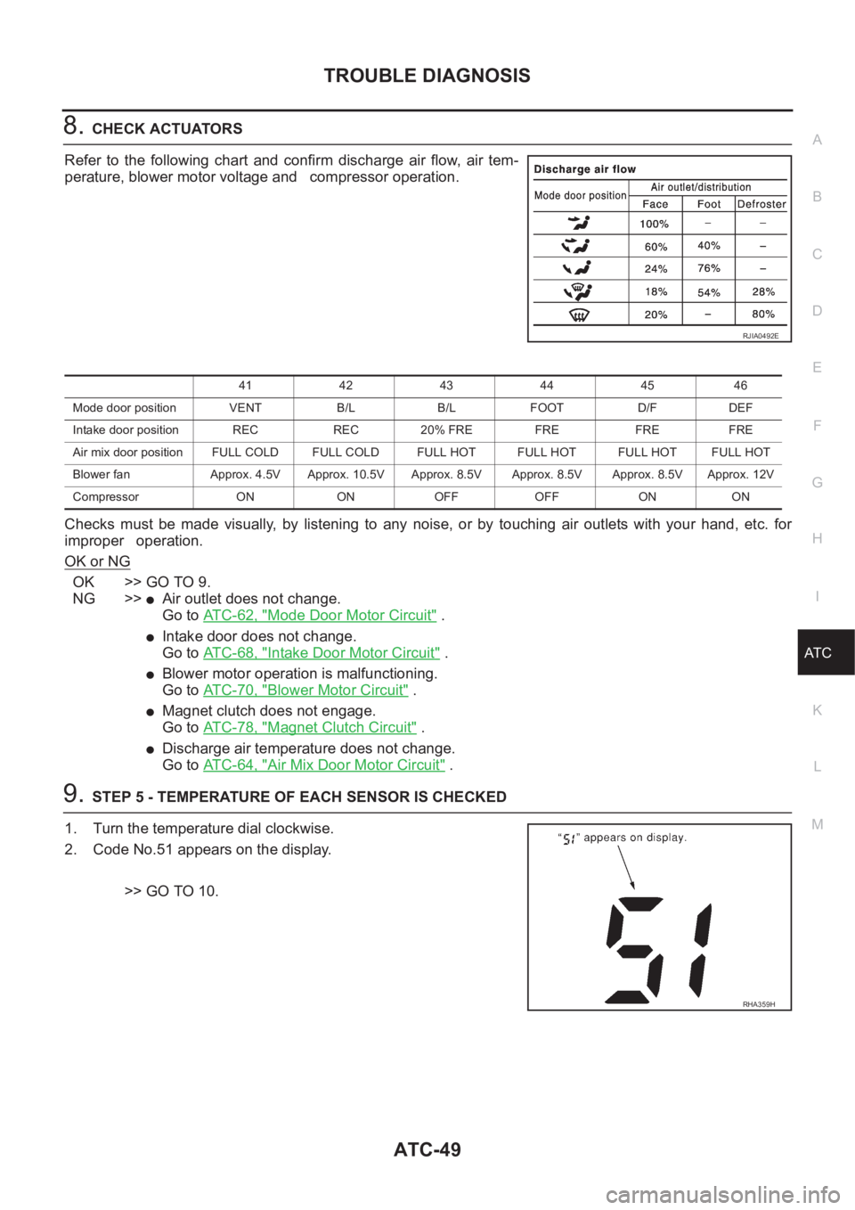
Refer to the following chart and confirm discharge air flow, air tem-
perature, blower motor voltage and compressor operation.
Checks must be made visually, by listening to any noise, or by touching air outlets with your hand, etc. for
improper operation.
OK or NG
OK >> GO TO 9.
NG >>
●Air outlet does not change.
Go to ATC-62, "
Mode Door Motor Circuit" .
●Intake door does not change.
Go to ATC-68, "
Intake Door Motor Circuit" .
●Blower motor operation is malfunctioning.
Go to ATC-70, "
Blower Motor Circuit" .
●Magnet clutch does not engage.
Go to ATC-78, "
Magnet Clutch Circuit" .
●Discharge air temperature does not change.
Go to ATC-64, "
Air Mix Door Motor Circuit" .
9.STEP 5 - TEMPERATURE OF EACH SENSOR IS CHECKED
1. Turn the temperature dial clockwise.
2. Code No.51 appears on the display.
>> GO TO 10.
RJIA0492E
41 42 43 44 45 46
Mode door position VENT B/L B/L FOOT D/F DEF
Intake door position REC REC 20% FRE FRE FRE FRE
Air mix door position FULL COLD FULL COLD FULL HOT FULL HOT FULL HOTFULL HOT
Blower fan Approx. 4.5V Approx. 10.5V Approx. 8.5V Approx. 8.5V Approx. 8.5V Approx. 12V
Compressor ON ON OFF OFF ON ON
RHA359H
Page 3331 of 3833
TROUBLE DIAGNOSIS
ATC-55
C
D
E
F
G
H
I
K
L
MA
B
AT C
CHECKING BLOWER
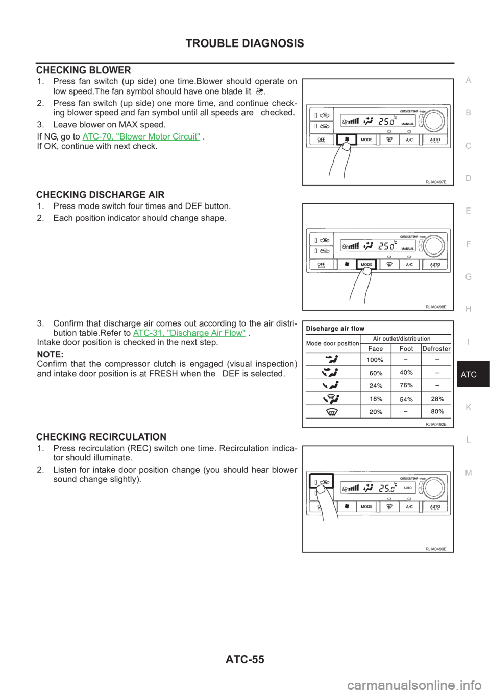
1. Press fan switch (up side) one time.Blower should operate on
low speed.The fan symbol should have one blade lit .
2. Press fan switch (up side) one more time, and continue check-
ing blower speed and fan symbol until all speeds are checked.
3. Leave blower on MAX speed.
If NG, go to ATC-70, "
Blower Motor Circuit" .
If OK, continue with next check.
CHECKING DISCHARGE AIR
1. Press mode switch four times and DEF button.
2. Each position indicator should change shape.
3. Confirm that discharge air comes out according to the air distri-
bution table.Refer to AT C - 3 1 , "
Discharge Air Flow" .
Intake door position is checked in the next step.
NOTE:
Confirm that the compressor clutch is engaged (visual inspection)
and intake door position is at FRESH when the DEF is selected.
CHECKING RECIRCULATION
1. Press recirculation (REC) switch one time. Recirculation indica-
tor should illuminate.
2. Listen for intake door position change (you should hear blower
sound change slightly).
RJIA0497E
RJIA0498E
RJIA0492E
RJIA0499E
Page 3332 of 3833
ATC-56
TROUBLE DIAGNOSIS
CHECKING TEMPERATURE DECREASE
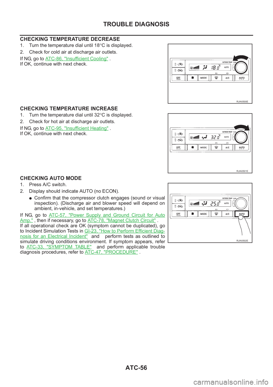
1. Turn the temperature dial until 18°C is displayed.
2. Check for cold air at discharge air outlets.
If NG, go to AT C - 8 6 , "
Insufficient Cooling" .
If OK, continue with next check.
CHECKING TEMPERATURE INCREASE
1. Turn the temperature dial until 32°C is displayed.
2. Check for hot air at discharge air outlets.
If NG, go to AT C - 9 5 , "
Insufficient Heating" .
If OK, continue with next check.
CHECKING AUTO MODE
1. Press A/C switch.
2. Display should indicate AUTO (no ECON).
●Confirm that the compressor clutch engages (sound or visual
inspection). (Discharge air and blower speed will depend on
ambient, in-vehicle, and set temperatures.)
If NG, go to AT C - 5 7 , "
Power Supply and Ground Circuit for Auto
Amp." , then if necessary, go to AT C - 7 8 , "Magnet Clutch Circuit" .
If all operational check are OK (symptom cannot be duplicated), go
to Incident Simulation Tests in GI-23, "
How to Perform Efficient Diag-
nosis for an Electrical Incident" and perform tests as outlined to
simulate driving conditions environment. If symptom appears, refer
to AT C - 3 3 , "
SYMPTOM TABLE" and perform applicable trouble
diagnosis procedures, refer to ATC-47, "
PROCEDURE" .
RJIA0500E
RJIA0501E
RJIA0502E