2001 NISSAN X-TRAIL sensor
[x] Cancel search: sensorPage 3546 of 3833
LT-56
INTERIOR ROOM LAMP
INTERIOR ROOM LAMP TIMER OPERATION
When interior room lamp switch is in the “DOOR” position, the time control unit keeps the interior room lamp
illuminated for about 30 seconds when:
●unlock signal is supplied from driver's door unlock sensor while all doors are closed and key is out of igni-
tion key cylinder
●key is removed from ignition key cylinder while all doors are closed
●driver's door is opened and then closed while key is out of the ignition key cylinder. (However, if the
driver's door is closed with the key inserted in the ignition key cylinder after the driver's door is opened
with the key removed, the timer is operated.)
The timer is canceled when:
●driver's door is locked,
●driver's door is opened, or
●ignition switch is turned ON.
ON-OFF CONTROL
When the driver side door, front passenger door, rear LH or RH door is opened, the interior room lamp turns
on while the interior room lamp switch is in the “DOOR” position.
Page 3550 of 3833
LT-60
INTERIOR ROOM LAMP
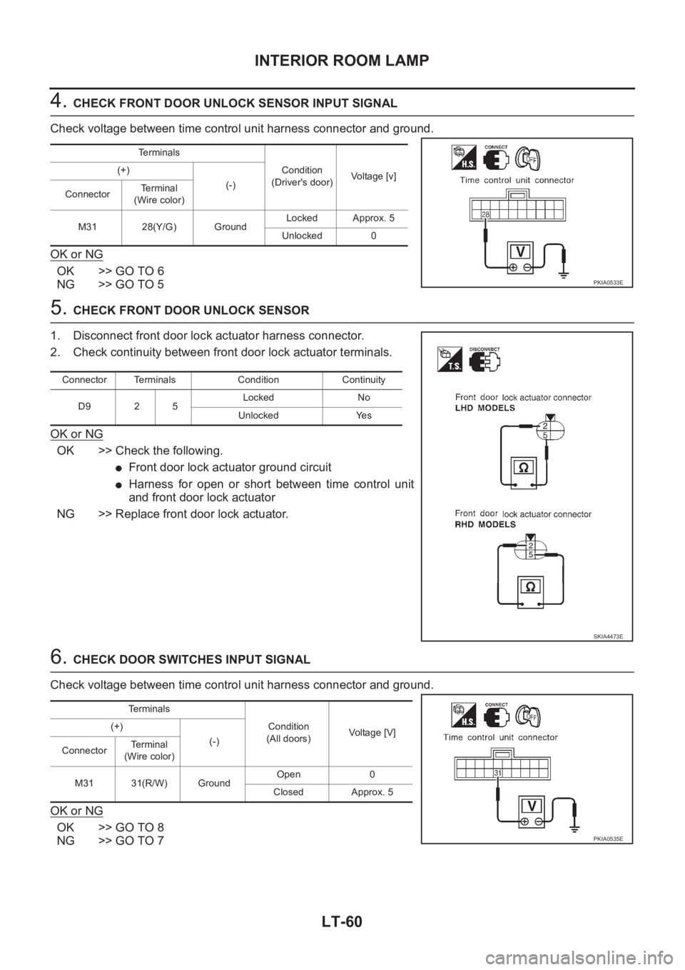
4. CHECK FRONT DOOR UNLOCK SENSOR INPUT SIGNAL
Check voltage between time control unit harness connector and ground.
OK or NG
OK >> GO TO 6
NG >> GO TO 5
5. CHECK FRONT DOOR UNLOCK SENSOR
1. Disconnect front door lock actuator harness connector.
2. Check continuity between front door lock actuator terminals.
OK or NG
OK >> Check the following.
●Front door lock actuator ground circuit
●Harness for open or short between time control unit
and front door lock actuator
NG >> Replace front door lock actuator.
6. CHECK DOOR SWITCHES INPUT SIGNAL
Check voltage between time control unit harness connector and ground.
OK or NG
OK >> GO TO 8
NG >> GO TO 7
Te r m i n a l s
Condition
(Driver's door)Voltage [v] (+)
(-)
ConnectorTe r m i n a l
(Wire color)
M31 28(Y/G) GroundLocked Approx. 5
Unlocked 0
PKIA0533E
Connector Terminals Condition Continuity
D9 2 5Locked No
Unlocked Yes
SKIA4473E
Terminals
Condition
(All doors)Voltag e [V] (+)
(-)
ConnectorTerminal
(Wire color)
M31 31(R/W) GroundOpen 0
Closed Approx. 5
PKIA0535E
Page 3553 of 3833
INTERIOR ROOM LAMP
LT-63
C
D
E
F
G
H
I
J
L
MA
B
LT
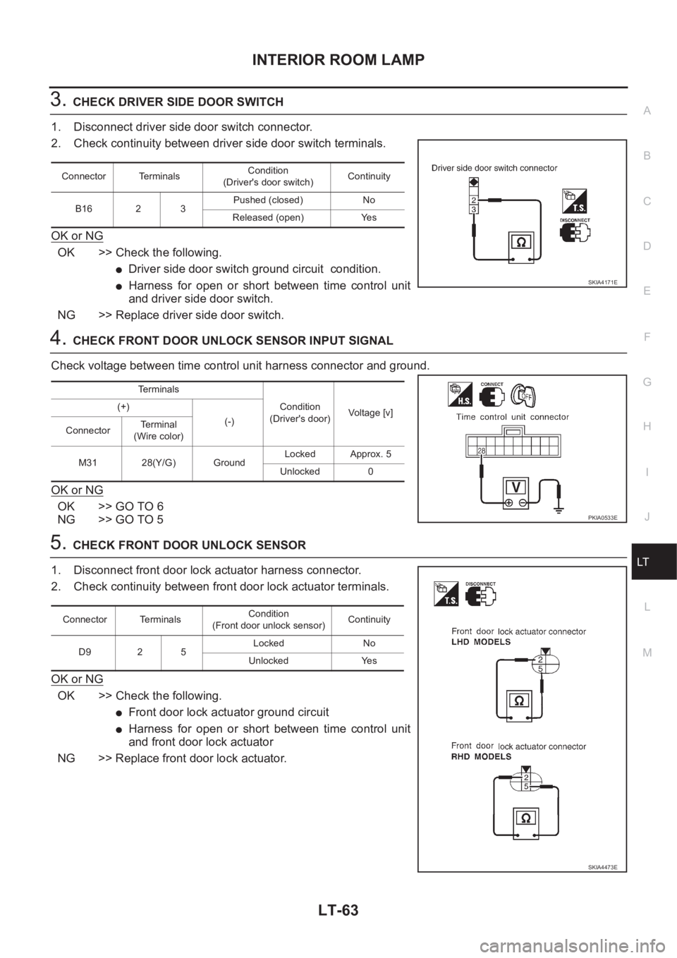
3.CHECK DRIVER SIDE DOOR SWITCH
1. Disconnect driver side door switch connector.
2. Check continuity between driver side door switch terminals.
OK or NG
OK >> Check the following.
●Driver side door switch ground circuit condition.
●Harness for open or short between time control unit
and driver side door switch.
NG >> Replace driver side door switch.
4.CHECK FRONT DOOR UNLOCK SENSOR INPUT SIGNAL
Check voltage between time control unit harness connector and ground.
OK or NG
OK >> GO TO 6
NG >> GO TO 5
5.CHECK FRONT DOOR UNLOCK SENSOR
1. Disconnect front door lock actuator harness connector.
2. Check continuity between front door lock actuator terminals.
OK or NG
OK >> Check the following.
●Front door lock actuator ground circuit
●Harness for open or short between time control unit
and front door lock actuator
NG >> Replace front door lock actuator.
Connector TerminalsCondition
(Driver's door switch)Continuity
B16 2 3Pushed (closed) No
Released (open) Yes
SKIA4171E
Terminals
Condition
(Driver's door)Voltage [v] (+)
(-)
ConnectorTerminal
(Wire color)
M31 28(Y/G) GroundLocked Approx. 5
Unlocked 0
PKIA0533E
Connector TerminalsCondition
(Front door unlock sensor)Continuity
D9 2 5Locked No
Unlocked Yes
SKIA4473E
Page 3559 of 3833
DI-1
DRIVER INFORMATION SYSTEM
K ELECTRICAL
CONTENTS
C
D
E
F
G
H
I
J
L
M
SECTION
A
B
DI
DRIVER INFORMATION SYSTEM
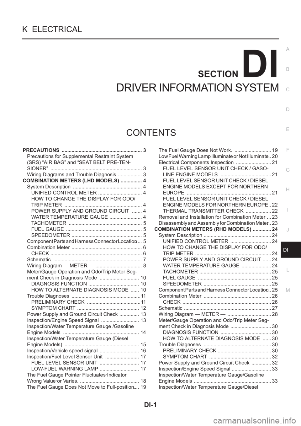
PRECAUTIONS .......................................................... 3
Precautions for Supplemental Restraint System
(SRS) “AIR BAG” and “SEAT BELT PRE-TEN-
SIONER” .................................................................. 3
Wiring Diagrams and Trouble Diagnosis .................. 3
COMBINATION METERS (LHD MODELS) ................ 4
System Description .................................................. 4
UNIFIED CONTROL METER ................................ 4
HOW TO CHANGE THE DISPLAY FOR ODO/
TRIP METER ........................................................ 4
POWER SUPPLY AND GROUND CIRCUIT ........ 4
WATER TEMPERATURE GAUGE ........................ 4
TACHOMETER ..................................................... 5
FUEL GAUGE ....................................................... 5
SPEEDOMETER ................................................... 5
Component Parts and Harness Connector Location ..... 5
Combination Meter ................................................... 6
CHECK .................................................................. 6
Schematic ................................................................ 7
Wiring Diagram — METER — .................................. 8
Meter/Gauge Operation and Odo/Trip Meter Seg-
ment Check in Diagnosis Mode ............................. 10
DIAGNOSIS FUNCTION ..................................... 10
HOW TO ALTERNATE DIAGNOSIS MODE ....... 10
Trouble Diagnoses .................................................. 11
PRELIMINARY CHECK ....................................... 11
SYMPTOM CHART ............................................. 12
Power Supply and Ground Circuit Check ............... 13
Inspection/Engine Speed Signal ............................ 13
Inspection/Water Temperature Gauge /Gasoline
Engine Models ....................................................... 14
Inspection/Water Temperature Gauge (Diesel
Engine Models) ...................................................... 15
Inspection/Vehicle speed signal ............................. 16
Inspection/Fuel Level Sensor Unit ......................... 17
FUEL LEVEL SENSOR UNIT ............................. 17
LOW-FUEL WARNING LAMP ............................. 17
The Fuel Gauge Pointer Fluctuates·Indicator
Wrong Value·or Varies. ........................................... 18
The Fuel Gauge Does Not Move to Full-position. ... 19The Fuel Gauge Does Not Work. ........................... 19
Low Fuel Warning Lamp Illuminate or Not Illuminate ... 20
Electrical Components Inspection .......................... 21
FUEL LEVEL SENSOR UNIT CHECK / GASO-
LINE ENGINE MODELS ..................................... 21
FUEL LEVEL SENSOR UNIT CHECK / DIESEL
ENGINE MODELS EXCEPT FOR NORTHERN
EUROPE ............................................................. 21
FUEL LEVEL SENSOR UNIT CHECK / DIESEL
ENGINE MODELS FOR NORTHERN EUROPE ... 22
THERMAL TRANSMITTER CHECK ................... 22
Removal and Installation for Combination Meter .... 23
Disassembly and Assembly for Combination Meter ... 23
COMBINATION METERS (RHD MODELS) .............. 24
System Description ................................................. 24
UNIFIED CONTROL METER ...........................
... 24
HOW TO CHANGE THE DISPLAY FOR ODO/
TRIP METER ....................................................... 24
POWER SUPPLY AND GROUND CIRCUIT ....... 24
WATER TEMPERATURE GAUGE ...................... 24
TACHOMETER .................................................... 25
FUEL GAUGE ..................................................... 25
SPEEDOMETER ................................................. 25
Component Parts and Harness Connector Location ... 25
Combination Meter .............................................. ... 26
CHECK ................................................................ 26
Schematic ............................................................... 27
Wiring Diagram — METER — ................................ 28
Meter/Gauge Operation and Odo/Trip Meter Seg-
ment Check in Diagnosis Mode .............................. 30
DIAGNOSIS FUNCTION ..................................... 30
HOW TO ALTERNATE DIAGNOSIS MODE ....... 30
Trouble Diagnoses ................................................. 30
PRELIMINARY CHECK ....................................... 30
SYMPTOM CHART ............................................. 32
Power Supply and Ground Circuit Check ............... 32
Inspection/Engine Speed Signal ............................. 33
Inspection/Water Temperature Gauge/Gasoline
Engine Models ........................................................ 33
Inspection/Water Temperature Gauge/Diesel
Page 3560 of 3833
DI-2
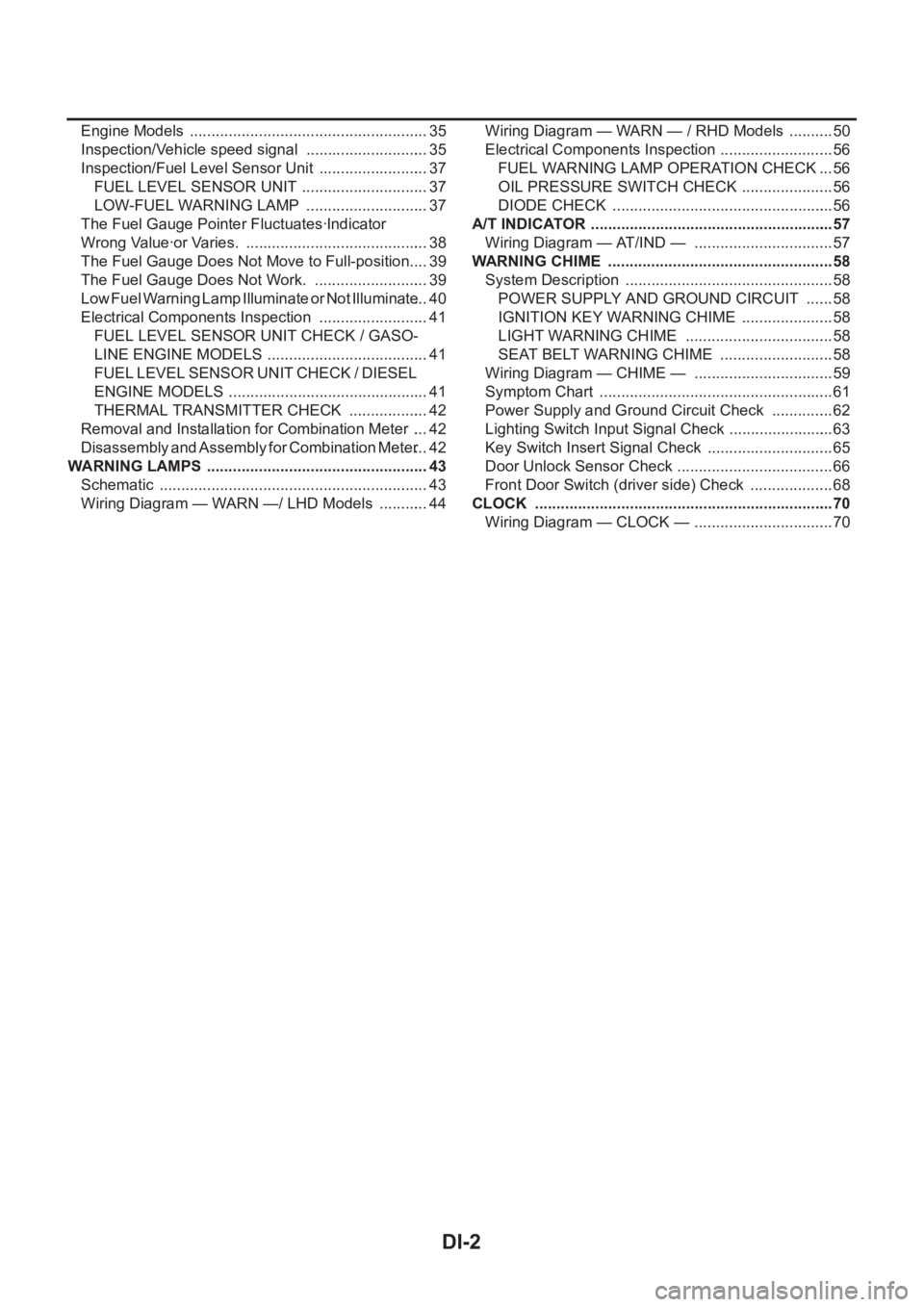
Engine Models ........................................................ 35
Inspection/Vehicle speed signal ............................. 35
Inspection/Fuel Level Sensor Unit .......................... 37
FUEL LEVEL SENSOR UNIT .............................. 37
LOW-FUEL WARNING LAMP ............................. 37
The Fuel Gauge Pointer Fluctuates·Indicator
Wrong Value·or Varies. ........................................... 38
The Fuel Gauge Does Not Move to Full-position. ... 39
The Fuel Gauge Does Not Work. ........................... 39
Low Fuel Warning Lamp Illuminate or Not Illuminate ... 40
Electrical Components Inspection .......................... 41
FUEL LEVEL SENSOR UNIT CHECK / GASO-
LINE ENGINE MODELS ...................................... 41
FUEL LEVEL SENSOR UNIT CHECK / DIESEL
ENGINE MODELS ............................................... 41
THERMAL TRANSMITTER CHECK ................... 42
Removal and Installation for Combination Meter .... 42
Disassembly and Assembly for Combination Meter ... 42
WARNING LAMPS .................................................... 43
Schematic ............................................................... 43
Wiring Diagram — WARN —/ LHD Models ............ 44Wiring Diagram — WARN — / RHD Models ........... 50
Electrical Components Inspection ........................... 56
FUEL WARNING LAMP OPERATION CHECK ... 56
OIL PRESSURE SWITCH CHECK ...................... 56
DIODE CHECK .................................................... 56
A/T INDICATOR ......................................................... 57
Wiring Diagram — AT/IND — ................................. 57
WARNING CHIME .................................................. ... 58
System Description ................................................. 58
POWER SUPPLY AND GROUND CIRCUIT ....... 58
IGNITION KEY WARNING CHIME ...................... 58
LIGHT WARNING CHIME ................................... 58
SEAT BELT WARNING CHIME ........................... 58
Wiring Diagram — CHIME — ................................. 59
Symptom Chart ....................................................... 61
Power Supply and Ground Circuit Check ............... 62
Lighting Switch Input Signal Check ......................... 63
Key Switch Insert Signal Check .............................. 65
Door Unlock Sensor Check ..................................... 66
Front Door Switch (driver side) Check .................... 68
CLOCK ...................................................................... 70
Wiring Diagram — CLOCK — ................................. 70
Page 3562 of 3833
DI-4
COMBINATION METERS (LHD MODELS)
COMBINATION METERS (LHD MODELS)
PFP:24810
System DescriptionEKS002Z7
UNIFIED CONTROL METER
●Speedometer, odo/trip meter, tachometer, fuel gauge and water temperature gauge are controlled totally
by control unit built-in combination meter.
●Digital meter is adopted for odo/trip meter.*
*The record of the odo meter is kept even if the battery cable is disconnected. The record of the trip meter
is erased when the battery cable is disconnected.
●Odo/trip meter segment can be checked in diagnosis mode.
●Meter/gauge can be checked in diagnosis mode.
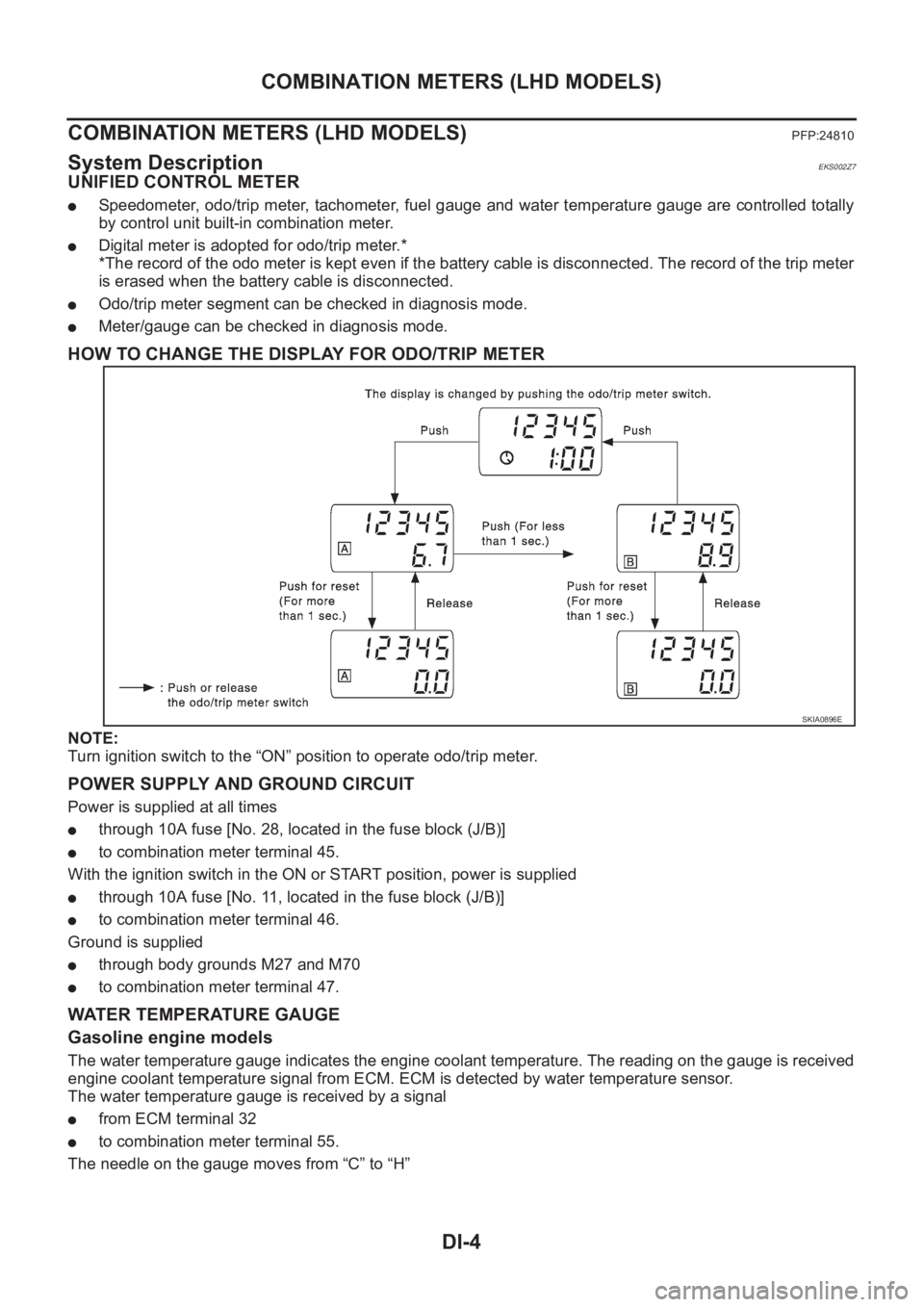
HOW TO CHANGE THE DISPLAY FOR ODO/TRIP METER
NOTE:
Turn ignition switch to the “ON” position to operate odo/trip meter.
POWER SUPPLY AND GROUND CIRCUIT
Power is supplied at all times
●through 10A fuse [No. 28, located in the fuse block (J/B)]
●to combination meter terminal 45.
With the ignition switch in the ON or START position, power is supplied
●through 10A fuse [No. 11, located in the fuse block (J/B)]
●to combination meter terminal 46.
Ground is supplied
●through body grounds M27 and M70
●to combination meter terminal 47.
WATER TEMPERATURE GAUGE
Gasoline engine models
The water temperature gauge indicates the engine coolant temperature. The reading on the gauge is received
engine coolant temperature signal from ECM. ECM is detected by water temperature sensor.
The water temperature gauge is received by a signal
●from ECM terminal 32
●to combination meter terminal 55.
The needle on the gauge moves from “C” to “H”
SKIA0896E
Page 3563 of 3833
COMBINATION METERS (LHD MODELS)
DI-5
C
D
E
F
G
H
I
J
L
MA
B
DI
Diesel engine models
The water temperature gauge indicates the engine coolant temperature. The reading on the gauge is based
on the resistance of the thermal transmitter.
As the temperature of the coolant increases, the resistance of the thermal transmitter decreases. A variable
ground is supplied to terminal 55 of the combination meter for the water temperature gauge. The needle on
the gauge moves from “C” to “H”.
TACHOMETER
The tachometer indicates engine speed in revolutions per minute (rpm).
The tachometer is regulated by a signal
●from terminal 36 (Gasoline engine models) or D1 (Diesel engine models) of the ECM
●to combination meter terminal 54 for the tachometer.
FUEL GAUGE
The fuel gauge indicates the approximate fuel level in the fuel tank.
The fuel gauge is regulated by a variable ground signal supplied
●from body grounds, B8 and B18
●through terminals 4 and 1 of the fuel level sensor unit and
●through terminals 1 and 3 of the Sub fuel level sensor unit
●to combination meter terminal 51 for the fuel gauge.
SPEEDOMETER
The combination meter provides a voltage signal to the vehicle speed signal from 4WD/ABS control unit (with-
out ESP) or 4WD control unit (with ESP).
The voltage is supplied
●from combination meter terminal 52 for the speedometer
●to terminal 20 of 4WD control unit (with ESP) or 4WD/ABS control unit (without ESP).
The speedometer converts the voltage into the vehicle speed displayed.
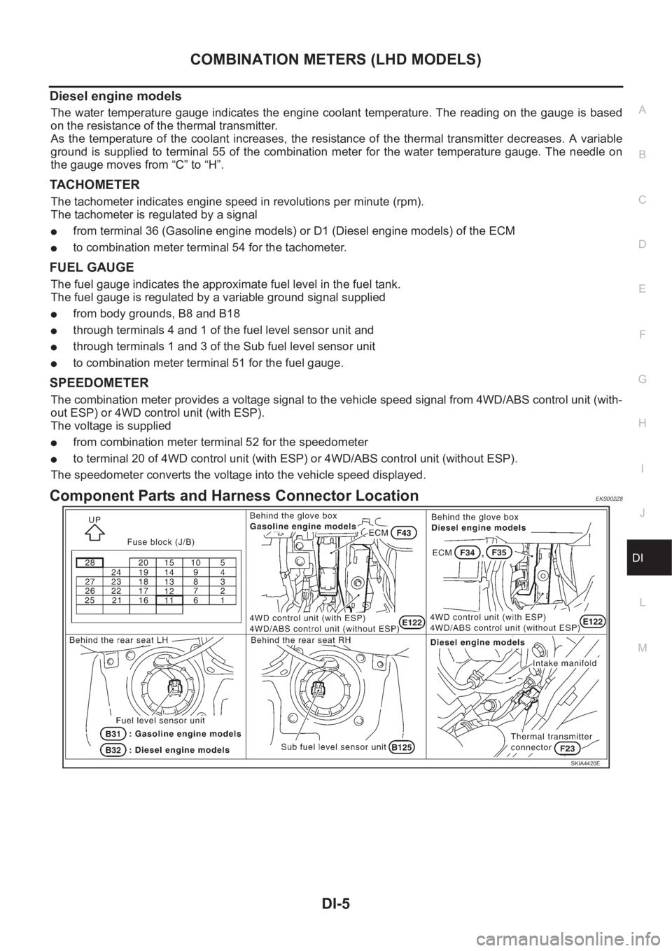
Component Parts and Harness Connector LocationEKS002Z8
SKIA4420E
Page 3570 of 3833
DI-12
COMBINATION METERS (LHD MODELS)
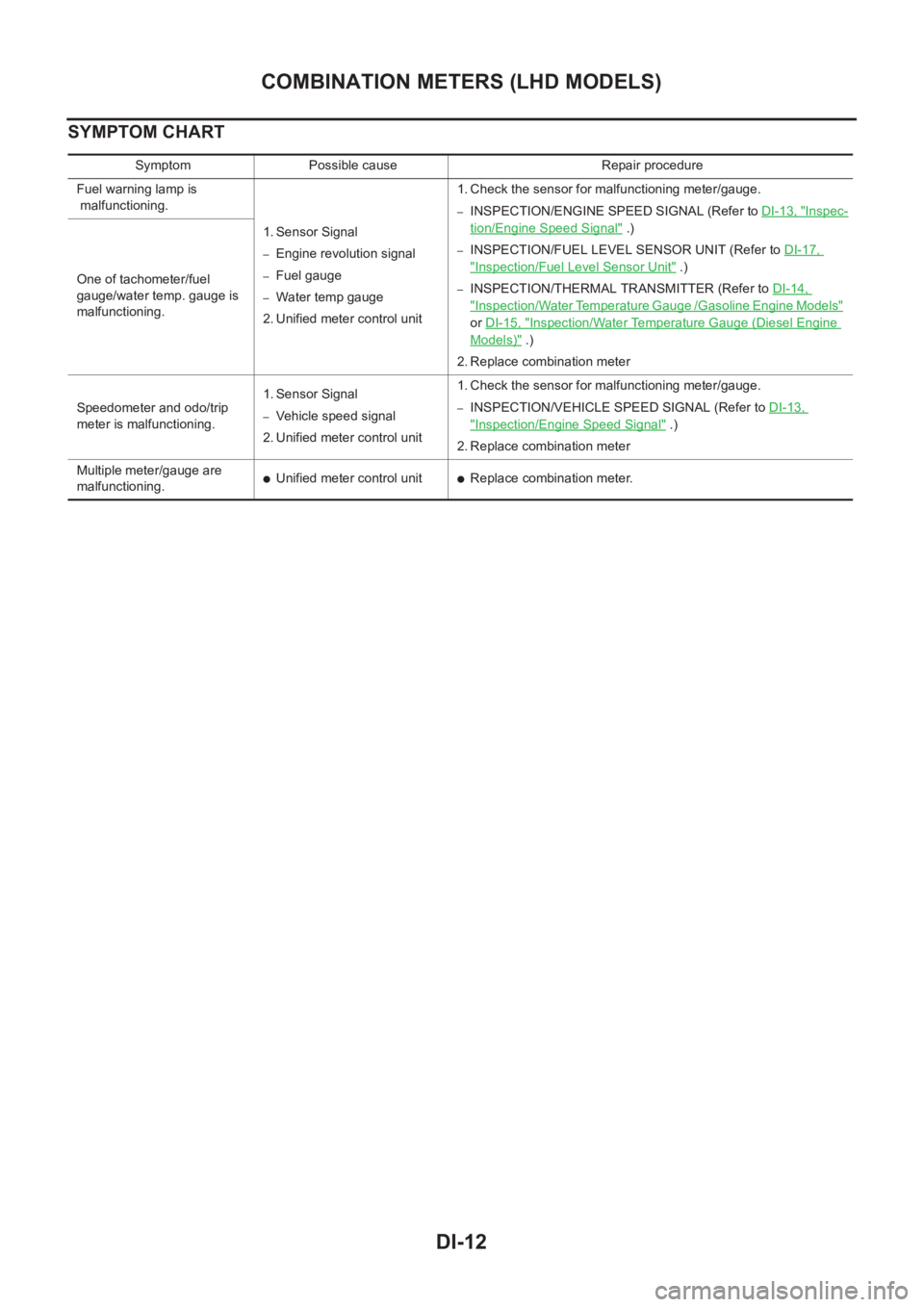
SYMPTOM CHART
Symptom Possible cause Repair procedure
Fuel warning lamp is
malfunctioning.
1. Sensor Signal
–Engine revolution signal
–Fuel gauge
–Water temp gauge
2. Unified meter control unit 1. Check the sensor for malfunctioning meter/gauge.
–INSPECTION/ENGINE SPEED SIGNAL (Refer to DI-13, "Inspec-
tion/Engine Speed Signal" .)
–INSPECTION/FUEL LEVEL SENSOR UNIT (Refer to DI-17,
"Inspection/Fuel Level Sensor Unit" .)
–INSPECTION/THERMAL TRANSMITTER (Refer to DI-14,
"Inspection/Water Temperature Gauge /Gasoline Engine Models"
or DI-15, "Inspection/Water Temperature Gauge (Diesel Engine
Models)" .)
2. Replace combination meter One of tachometer/fuel
gauge/water temp. gauge is
malfunctioning.
Speedometer and odo/trip
meter is malfunctioning.1. Sensor Signal
–Vehicle speed signal
2. Unified meter control unit 1. Check the sensor for malfunctioning meter/gauge.–INSPECTION/VEHICLE SPEED SIGNAL (Refer to DI-13,
"Inspection/Engine Speed Signal" .)
2. Replace combination meter
Multiple meter/gauge are
malfunctioning.
●Unified meter control unit●Replace combination meter.