Page 3354 of 3833
ATC-78
TROUBLE DIAGNOSIS
Magnet Clutch Circuit
EJS001H5
SYMPTOM: Magnet clutch does not engage.
INSPECTION FLOW
*1AT C - 4 7 , "PROCEDURE", see No. 1. *2ATC-100, "Ambient Sensor Circuit".*3ATC-102, "In-vehicle Sensor Cir-
cuit".
*4ATC-105, "
Sunload Sensor Circuit".*5ATC-64, "Air Mix Door Motor Circuit".*6ATC-47, "PROCEDURE", see No.
14.
*7AT C - 7 8 , "
Magnet Clutch Circuit".*8ATC-92, "TROUBLE DIAGNOSES
FOR UNUSUAL PRESSURE".*9ATC-54, "
Operational Check".
*10AT C - 4 7 , "
PROCEDURE", see No. 5
to 7.*11ATC-54, "Operational Check".*12ATC-33, "SYMPTOM TABLE".
*13ATC-108, "
Intake Sensor Circuit".
RJIA0533E
Page 3355 of 3833
TROUBLE DIAGNOSIS
ATC-79
C
D
E
F
G
H
I
K
L
MA
B
AT C
SYSTEM DESCRIPTION
Auto amplifier controls compressor operation by ambient temperature and signal from ECM.
Low Temperature Protection Control (With Gasoline Engine)
Auto amplifier will turn the compressor ON or OFF as determined by
a signal detected by ambient sensor.
When ambient temperatures are greater than -2°C, the compressor
turns ON. The compressor turns OFF when ambient temperatures
are less than -5°C.
Evaporator Freeze Protection Control (With Diesel Engine)
Auto amplifier will turn the compressor ON or OFF as determined by
a signal detected by intake sensor.
When intake temperatures are greater than 4°C, the compressor
turns ON. The compressor turns OFF when intake temperatures are
less than 2.5°C.
DIAGNOSTIC PROCEDURE
SYMPTOM: Magnet clutch does not engage when A/C switch is ON.
RHA094GB
RJIA0534E
RJIA0535E
Page 3357 of 3833

TROUBLE DIAGNOSIS
ATC-81
C
D
E
F
G
H
I
K
L
MA
B
AT C
4.CHECK A/C RELAY AFTER DISCONNECTING IT
Refer to ATC-84, "
A/C Relay" .
OK or NG
OK >> Reconnect A/C relay. And GO TO 5.
NG >> 1. replace A/C relay.
2. Go to self-diagnosis AT C - 4 7 , "
PROCEDURE" and perform self-diagnosis STEP-4.Confirm that
magnet clutch operation is normal.
5.CHECK COIL SIDE CIRCUIT OF A/C RELAY
OK or NG
OK >> GO TO 6.
NG >> Repair harness or connector.
6.CHECK AMBIENT SENSOR
Refer to ATC-100, "
Ambient Sensor Circuit" .
OK or NG
OK >>●With gasoline engine: GO TO 7.
●With diesel engine: GO TO 14.
NG >> Repair or replace the malfunctioning part(s).
7.CHECK REFRIGERANT PRESSURE SENSOR (QR ENGINE)
Refer to ATC-85, "
Refrigerant Pressure Sensor (With Gasoline Engine)" .
OK or NG
OK >> GO TO 8.
NG >> Repair or replace the malfunctioning part(s).
8.CHECK VOLTAGE FOR AUTO AMP. (COMPRESSOR ON SIGNAL)
OK or NG
OK >> GO TO 9.
NG >>
●If the voltage is approx. 4.8V when the A/C switch is
ON: Replace the auto amp.
●If the voltage is approx. 0V when the A/C switch is OFF: GO TO 12.
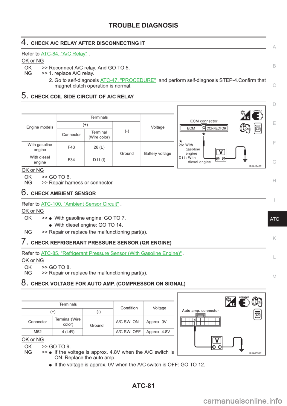
Engine modelsTerminals
Voltag e (+)
(-)
ConnectorTerminal
(Wire color)
With gasoline
engineF43 26 (L)
Ground Battery voltage
With diesel
engineF34 D11 (I)
RJIA1946E
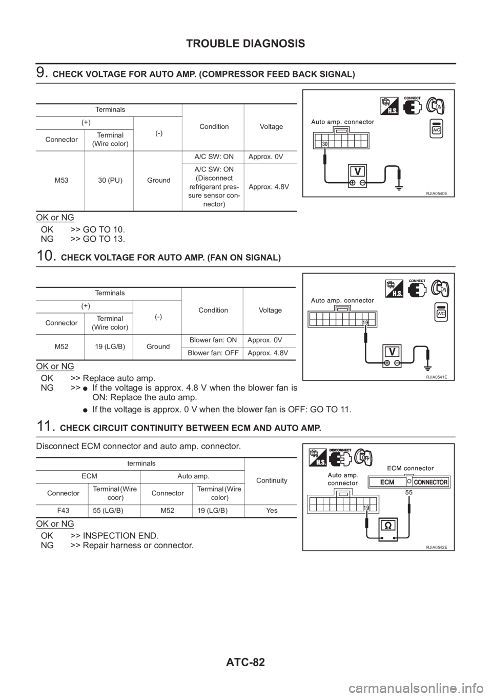
Terminals
Condition Voltage
(+) (-)
ConnectorTe r m i n a l ( W i r e
color)
GroundA/C SW: ON Approx. 0V
M52 4 (L/R) A/C SW: OFF Approx. 4.8V
RJIA0539E
Page 3358 of 3833

ATC-82
TROUBLE DIAGNOSIS
9. CHECK VOLTAGE FOR AUTO AMP. (COMPRESSOR FEED BACK SIGNAL)
OK or NG
OK >> GO TO 10.
NG >> GO TO 13.
10. CHECK VOLTAGE FOR AUTO AMP. (FAN ON SIGNAL)
OK or NG
OK >> Replace auto amp.
NG >>
●If the voltage is approx. 4.8 V when the blower fan is
ON: Replace the auto amp.
●If the voltage is approx. 0 V when the blower fan is OFF: GO TO 11.
11 . CHECK CIRCUIT CONTINUITY BETWEEN ECM AND AUTO AMP.
Disconnect ECM connector and auto amp. connector.
OK or NG
OK >> INSPECTION END.
NG >> Repair harness or connector.
Terminals
Condition Voltage (+)
(-)
ConnectorTerminal
(Wire color)
M53 30 (PU) GroundA/C SW: ON Approx. 0V
A/C SW: ON
(Disconnect
refrigerant pres-
sure sensor con-
nector)Approx. 4.8V
RJIA0540E
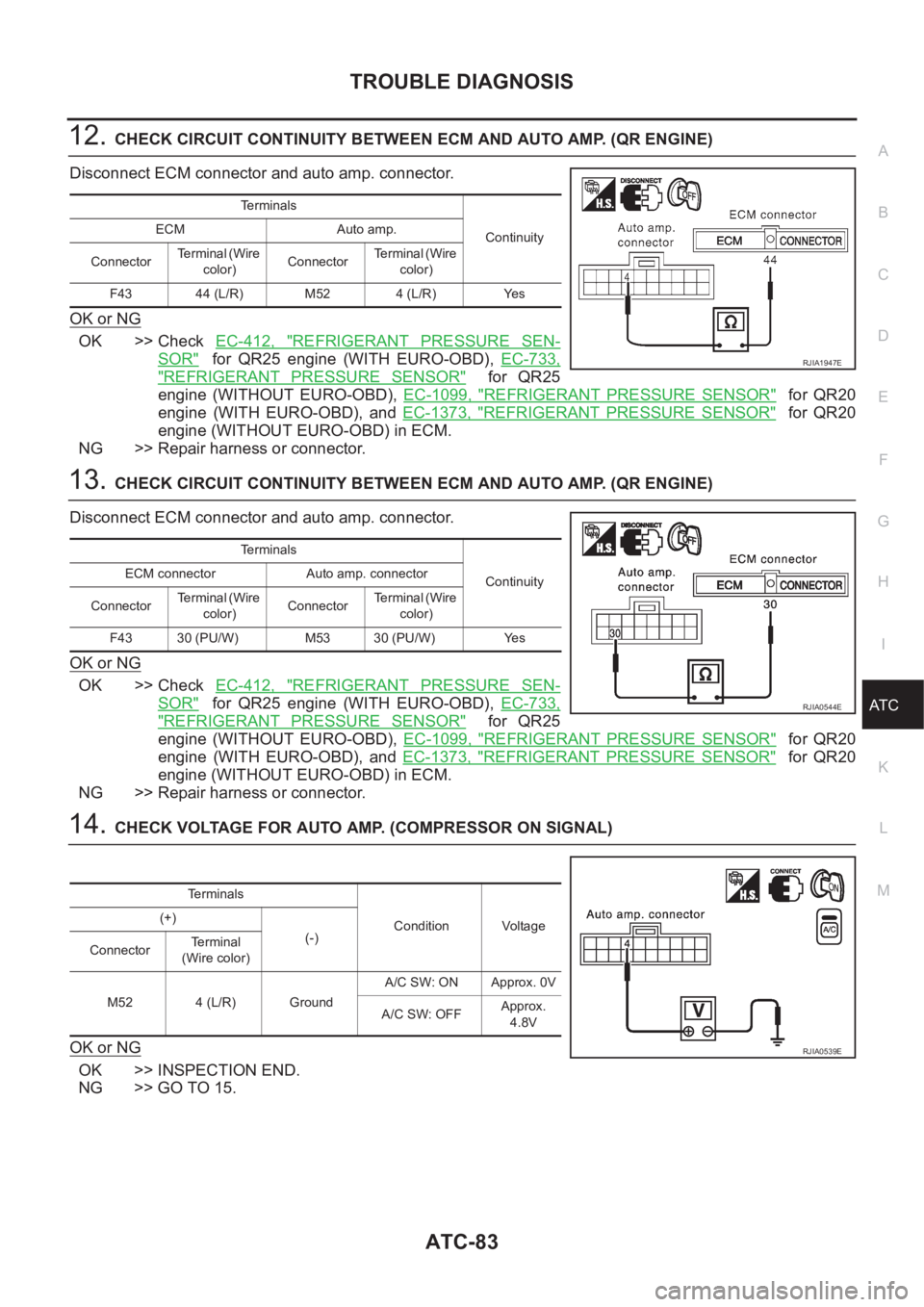
Terminals
Condition Voltage (+)
(-)
ConnectorTerminal
(Wire color)
M52 19 (LG/B) GroundBlower fan: ON Approx. 0V
Blower fan: OFF Approx. 4.8V
RJIA0541E
terminals
Continuity ECM Auto amp.
ConnectorTerminal (Wire
coor)ConnectorTerminal (Wire
color)
F43 55 (LG/B) M52 19 (LG/B) Yes
RJIA0542E
Page 3359 of 3833

TROUBLE DIAGNOSIS
ATC-83
C
D
E
F
G
H
I
K
L
MA
B
AT C
12.CHECK CIRCUIT CONTINUITY BETWEEN ECM AND AUTO AMP. (QR ENGINE)
Disconnect ECM connector and auto amp. connector.
OK or NG
OK >> Check EC-412, "REFRIGERANT PRESSURE SEN-
SOR" for QR25 engine (WITH EURO-OBD), EC-733,
"REFRIGERANT PRESSURE SENSOR" for QR25
engine (WITHOUT EURO-OBD), EC-1099, "
REFRIGERANT PRESSURE SENSOR" for QR20
engine (WITH EURO-OBD), and EC-1373, "
REFRIGERANT PRESSURE SENSOR" for QR20
engine (WITHOUT EURO-OBD) in ECM.
NG >> Repair harness or connector.
13.CHECK CIRCUIT CONTINUITY BETWEEN ECM AND AUTO AMP. (QR ENGINE)
Disconnect ECM connector and auto amp. connector.
OK or NG
OK >> Check EC-412, "REFRIGERANT PRESSURE SEN-
SOR" for QR25 engine (WITH EURO-OBD), EC-733,
"REFRIGERANT PRESSURE SENSOR" for QR25
engine (WITHOUT EURO-OBD), EC-1099, "
REFRIGERANT PRESSURE SENSOR" for QR20
engine (WITH EURO-OBD), and EC-1373, "
REFRIGERANT PRESSURE SENSOR" for QR20
engine (WITHOUT EURO-OBD) in ECM.
NG >> Repair harness or connector.
14.CHECK VOLTAGE FOR AUTO AMP. (COMPRESSOR ON SIGNAL)
OK or NG
OK >> INSPECTION END.
NG >> GO TO 15.
Te r m i n a l s
Continuity ECM Auto amp.
ConnectorTerminal (Wire
color)ConnectorTerminal (Wire
color)
F43 44 (L/R) M52 4 (L/R) Yes
RJIA1947E
Te r m i n a l s
Continuity ECM connector Auto amp. connector
ConnectorTerminal (Wire
color)ConnectorTerminal (Wire
color)
F43 30 (PU/W) M53 30 (PU/W) Yes
RJIA0544E
Terminals
Condition Voltage (+)
(-)
ConnectorTerminal
(Wire color)
M52 4 (L/R) GroundA/C SW: ON Approx. 0V
A/C SW: OFFApprox.
4.8V
RJIA0539E
Page 3361 of 3833
TROUBLE DIAGNOSIS
ATC-85
C
D
E
F
G
H
I
K
L
MA
B
AT C
Refrigerant Pressure Sensor (With Gasoline Engine)
The refrigerant pressure sensor is attached to the liquid tank (con-
denser).
Dual-Pressure Switch (With Diesel Engine)
Thermal Protector (With diesel engine)
Check continuity between compressor harness terminal and field
coil.
RJIA0690E
SHA315F
Compressor: ON
kPa (bar, kg/cm2 , psi)Compressor: OFF
kPa (bar, kg/cm2 , psi)
Low-pressure side 186 (1.86, 1.9, 27) 177 (1.77, 1.8, 26)
High-pressure side 1,569 (15.7, 16, 228) 2,746 (27.5, 28, 398)
RJIA0691E
RHA671H
Page 3369 of 3833

TROUBLE DIAGNOSIS
ATC-93
C
D
E
F
G
H
I
K
L
MA
B
AT C
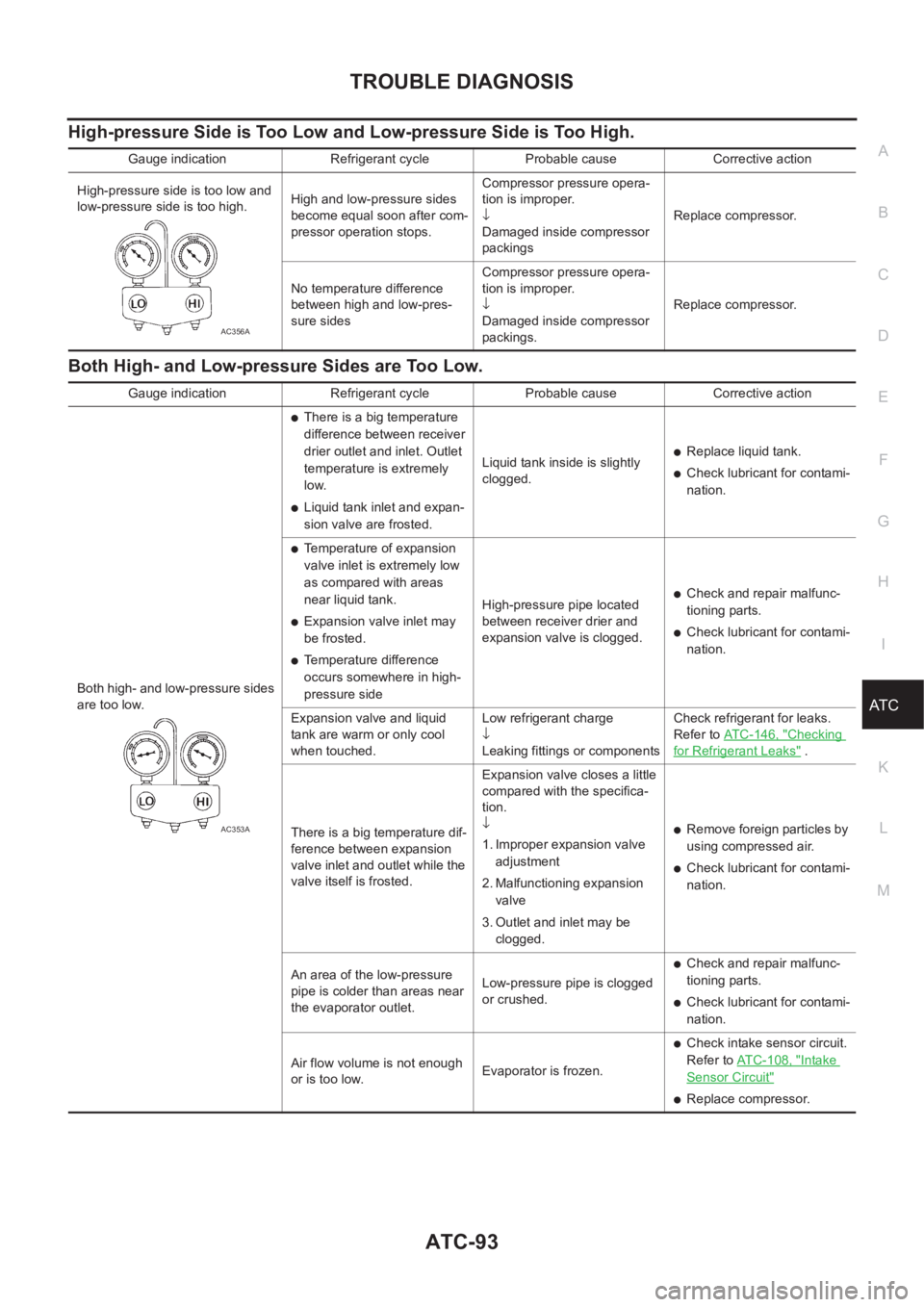
High-pressure Side is Too Low and Low-pressure Side is Too High.
Both High- and Low-pressure Sides are Too Low.
Gauge indication Refrigerant cycle Probable cause Corrective action
High-pressure side is too low and
low-pressure side is too high.High and low-pressure sides
become equal soon after com-
pressor operation stops.Compressor pressure opera-
tion is improper.
↓
Damaged inside compressor
packingsReplace compressor.
No temperature difference
between high and low-pres-
sure sidesCompressor pressure opera-
tion is improper.
↓
Damaged inside compressor
packings.Replace compressor.
AC356A
Gauge indication Refrigerant cycle Probable cause Corrective action
Both high- and low-pressure sides
are too low.
●There is a big temperature
difference between receiver
drier outlet and inlet. Outlet
temperature is extremely
low.
●Liquid tank inlet and expan-
sion valve are frosted.Liquid tank inside is slightly
clogged.
●Replace liquid tank.
●Check lubricant for contami-
nation.
●Temperature of expansion
valve inlet is extremely low
as compared with areas
near liquid tank.
●Expansion valve inlet may
be frosted.
●Temperature difference
occurs somewhere in high-
pressure sideHigh-pressure pipe located
between receiver drier and
expansion valve is clogged.
●Check and repair malfunc-
tioning parts.
●Check lubricant for contami-
nation.
Expansion valve and liquid
tank are warm or only cool
when touched.Low refrigerant charge
↓
Leaking fittings or componentsCheck refrigerant for leaks.
Refer to ATC-146, "
Checking
for Refrigerant Leaks" .
There is a big temperature dif-
ference between expansion
valve inlet and outlet while the
valve itself is frosted.Expansion valve closes a little
compared with the specifica-
tion.
↓
1. Improper expansion valve
adjustment
2. Malfunctioning expansion
valve
3. Outlet and inlet may be
clogged.
●Remove foreign particles by
using compressed air.
●Check lubricant for contami-
nation.
An area of the low-pressure
pipe is colder than areas near
the evaporator outlet.Low-pressure pipe is clogged
or crushed.
●Check and repair malfunc-
tioning parts.
●Check lubricant for contami-
nation.
Air flow volume is not enough
or is too low.Evaporator is frozen.
●Check intake sensor circuit.
Refer to AT C - 1 0 8 , "
Intake
Sensor Circuit"
●Replace compressor.
AC353A
Page 3372 of 3833
ATC-96
TROUBLE DIAGNOSIS
*10 QR25 engine; (WITH EURO-OBD)
EC-153, "
ENGINE COOLANT TEM-
PERATURE SENSOR" .
QR25 engine; (WITHOOUT EUR-
OBD)EC-527, "
ENGINE COOLANT
TEMPERATURE SENSOR" .
QR20 engine; (WITH EURO-OBD)
EC-885, "
ENGINE COOLANT TEM-
PERATURE SENSOR" .
QR20 engine; (WITHOUT EURO-
OBD)EC-1213, "
ENGINE COOLANT
TEMPERATURE SENSOR" .
YD engine; EC-1508, "
SYSTEM
DESCRIPTION" .*11 QR engine; CO-9, "
Changing Engine
Coolant" .
YD engine; CO-29, "
Changing
Engine Coolant" .*12 QR engine; CO-9, "
Changing Engine
Coolant" .
YD engine; CO-29, "
Changing
Engine Coolant" .
*13 QR engine; CO-12, "
Checking Radi-
ator Cap" .
YD engine; CO-33, "
Checking Radi-
ator Cap" .