2001 NISSAN X-TRAIL sensor
[x] Cancel search: sensorPage 3108 of 3833
BL-56
MULTI-REMOTE CONTROL SYSTEM
System Description
EIS001RE
FUNCTION
Multi-remote control system has the following function.
●Door lock (and set super lock)
●Door unlock (and release super lock)
●Hazard reminder
LOCK OPERATION
To lock door by multi-remote controller, the ignition switch must be at OFF.
When the LOCK signal is input to multi-remote control unit (the antenna of the system is combined with multi-
remote control unit), ground is supplied
●through multi-remote control unit terminal 5
●to time control unit terminal 32.
Then time control unit operates to lock doors and set super lock (models with super lock).
UNLOCK OPERATION
When the UNLOCK signal is input to multi-remote control unit (the antenna of the system is combined with
multi-remote control unit), ground is supplied
●through multi-remote control unit terminal 6
●to time control unit terminal 33.
Time control unit operates to unlock driver's door and release super lock (models with super lock).
Then, if an unlock signal is sent from the remote controller again within 5 seconds, all other doors will be
unlocked.
HAZARD REMINDER
When the doors are locked or unlocked by multi-remote controller (signal from driver side unlock sensor), sup-
ply power to hazard warning lamp flashes as follows
●Lock operation: Flash once
●Unlock operation: Flash twice
MULTI-REMOTE CONTROLLER ID CODE ENTRY
A maximum of four remote controllers can be entered.
To enter ID code entry, the following signals must be input to the multi-remote control unit.
●Ignition switch (ON)
●Signal from remote controller
For detailed procedure, refer to BL-63, "
ID Code Entry Procedure" .
Page 3277 of 3833
ATC-1
AUTOMATIC AIR CONDITIONER
J AIR CONDITIONER
CONTENTS
C
D
E
F
G
H
I
K
L
M
SECTION
A
B
AT C
AUTOMATIC AIR CONDITIONER
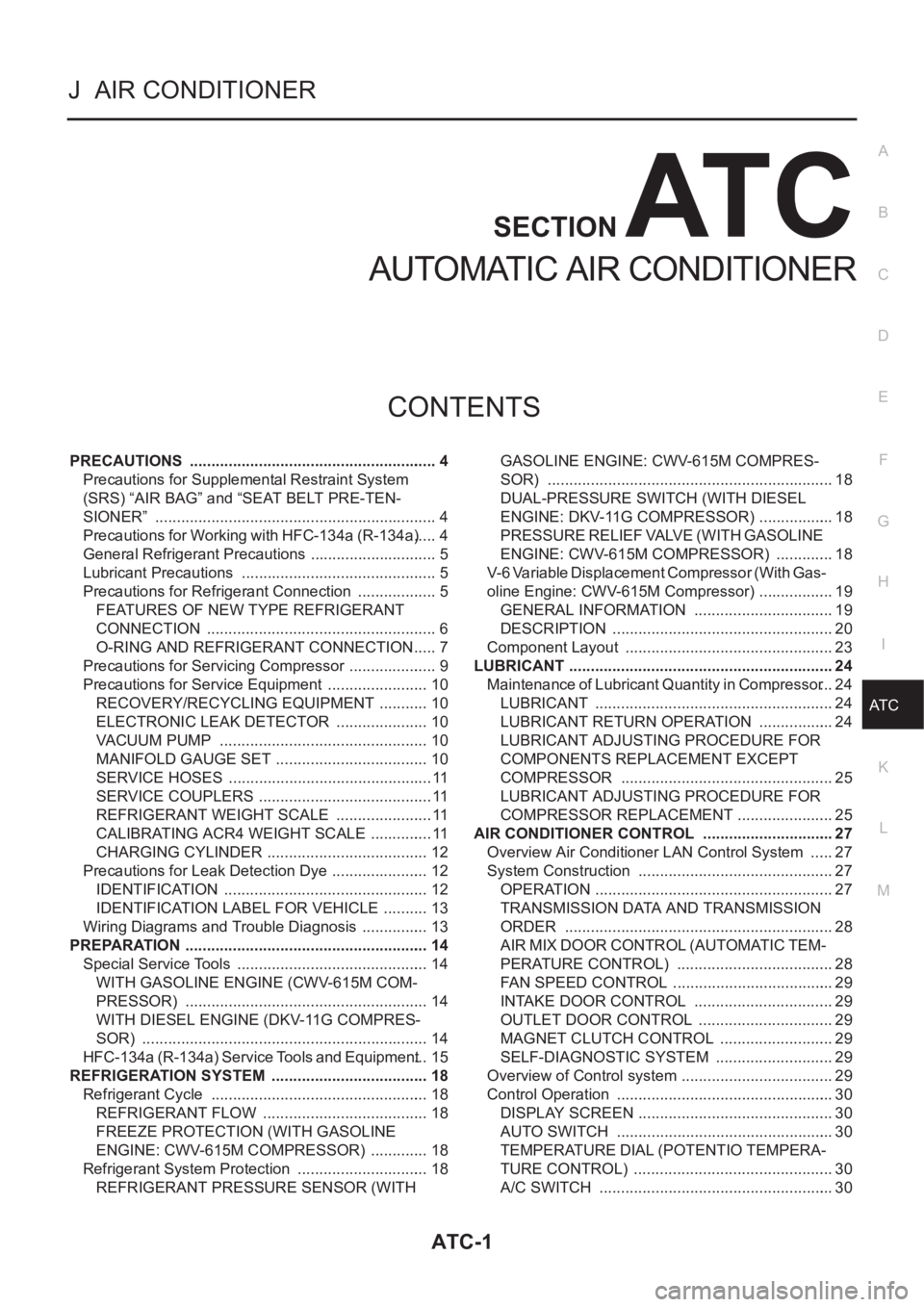
PRECAUTIONS .......................................................... 4
Precautions for Supplemental Restraint System
(SRS) “AIR BAG” and “SEAT BELT PRE-TEN-
SIONER” .................................................................. 4
Precautions for Working with HFC-134a (R-134a) ..... 4
General Refrigerant Precautions .............................. 5
Lubricant Precautions .............................................. 5
Precautions for Refrigerant Connection ................... 5
FEATURES OF NEW TYPE REFRIGERANT
CONNECTION ...................................................... 6
O-RING AND REFRIGERANT CONNECTION ..... 7
Precautions for Servicing Compressor ..................... 9
Precautions for Service Equipment ........................ 10
RECOVERY/RECYCLING EQUIPMENT ............ 10
ELECTRONIC LEAK DETECTOR ...................... 10
VACUUM PUMP ................................................. 10
MANIFOLD GAUGE SET .................................... 10
SERVICE HOSES ................................................ 11
SERVICE COUPLERS ......................................... 11
REFRIGERANT WEIGHT SCALE ....................... 11
CALIBRATING ACR4 WEIGHT SCALE ............... 11
CHARGING CYLINDER ...................................... 12
Precautions for Leak Detection Dye ....................... 12
IDENTIFICATION ................................................ 12
IDENTIFICATION LABEL FOR VEHICLE ........... 13
Wiring Diagrams and Trouble Diagnosis ................ 13
PREPARATION ......................................................... 14
Special Service Tools ............................................. 14
WITH GASOLINE ENGINE (CWV-615M COM-
PRESSOR) ......................................................... 14
WITH DIESEL ENGINE (DKV-11G COMPRES-
SOR) ................................................................... 14
HFC-134a (R-134a) Service Tools and Equipment ... 15
REFRIGERATION SYSTEM ..................................... 18
Refrigerant Cycle ................................................... 18
REFRIGERANT FLOW ....................................... 18
FREEZE PROTECTION (WITH GASOLINE
ENGINE: CWV-615M COMPRESSOR) .............. 18
Refrigerant System Protection ............................... 18
REFRIGERANT PRESSURE SENSOR (WITH GASOLINE ENGINE: CWV-615M COMPRES-
SOR) ................................................................... 18
DUAL-PRESSURE SWITCH (WITH DIESEL
ENGINE: DKV-11G COMPRESSOR) .................. 18
PRESSURE RELIEF VALVE (WITH GASOLINE
ENGINE: CWV-615M COMPRESSOR) .............. 18
V-6 Variable Displacement Compressor (With Gas-
oline Engine: CWV-615M Compressor) .................. 19
GENERAL INFORMATION ................................. 19
DESCRIPTION .................................................... 20
Component Layout ................................................. 23
LUBRICANT .............................................................. 24
Maintenance of Lubricant Quantity in Compressor ... 24
LUBRICANT ........................................................ 24
LUBRICANT RETURN OPERATION .................. 24
LUBRICANT ADJUSTING PROCEDURE FOR
COMPONENTS REPLACEMENT EXCEPT
COMPRESSOR .................................................. 25
LUBRICANT ADJUSTING PROCEDURE FOR
COMPRESSOR REPLACEMENT ....................... 25
AIR CONDITIONER CONTROL ............................... 27
Overview Air Conditioner LAN Control System ...... 27
System Construction .............................................. 27
OPERATION ........................................................ 27
TRANSMISSION DATA AND TRANSMISSION
ORDER ............................................................... 28
AIR MIX DOOR CONTROL (AUTOMATIC TEM-
PERATURE CONTROL) ..................................... 28
FAN SPEED CONTROL ...................................... 29
INTAKE DOOR CONTROL ................................. 29
OUTLET DOOR CONTROL ................................ 29
MAGNET CLUTCH CONTROL ........................... 29
SELF-DIAGNOSTIC SYSTEM ............................ 29
Overview of Control system .................................... 29
Control Operation ................................................... 30
DISPLAY SCREEN .............................................. 30
AUTO SWITCH ................................................... 30
TEMPERATURE DIAL (POTENTIO TEMPERA-
TURE CONTROL) ............................................... 30
A/C SWITCH ....................................................... 30
Page 3278 of 3833
ATC-2
DEFROSTER (DEF) SWITCH ............................. 30
MODE SWITCH ................................................... 30
FAN SWITCH ...................................................... 30
OFF SWITCH ...................................................... 30
FRESH (FRE) SWITCH ....................................... 30
RECIRCULATION (REC) SWITCH ..................... 30
Discharge Air Flow ................................................. 31
System Description ................................................. 32
SWITCHES AND THEIR CONTROL FUNCTION ... 32
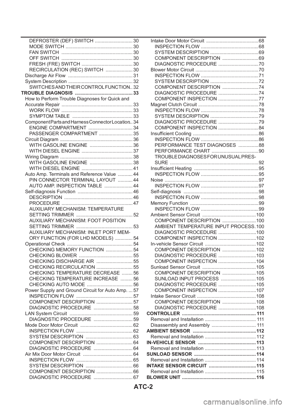
TROUBLE DIAGNOSIS ............................................ 33
How to Perform Trouble Diagnoses for Quick and
Accurate Repair ...................................................... 33
WORK FLOW ...................................................... 33
SYMPTOM TABLE .............................................. 33
Component Parts and Harness Connector Location ... 34
ENGINE COMPARTMENT .................................. 34
PASSENGER COMPARTMENT .......................... 35
Circuit Diagram ....................................................... 36
WITH GASOLINE ENGINE ................................. 36
WITH DIESEL ENGINE ....................................... 37
Wiring Diagram ....................................................... 38
WITH GASOLINE ENGINE ................................. 38
WITH DIESEL ENGINE ....................................... 41
Auto Amp. Terminals and Reference Value ............ 44
PIN CONNECTOR TERMINAL LAYOUT ............ 44
AUTO AMP. INSPECTION TABLE ...................... 44
Self-diagnosis Function .......................................... 46
DESCRIPTION .................................................... 46
PROCEDURE ...................................................... 47
AUXILIARY MECHANISM: TEMPERATURE
SETTING TRIMMER ........................................... 52
AUXILIARY MECHANISM: FOOT POSITION
SETTING TRIMMER ........................................... 53
AUXILIARY MECHANISM: INLET PORT MEM-
ORY FUNCTION (FOR LHD MODELS) .............. 54
Operational Check .................................................. 54
CHECKING MEMORY FUNCTION ..................... 54
CHECKING BLOWER ......................................... 55
CHECKING DISCHARGE AIR ............................ 55
CHECKING RECIRCULATION ............................ 55
CHECKING TEMPERATURE DECREASE ......... 56
CHECKING TEMPERATURE INCREASE .......... 56
CHECKING AUTO MODE ................................... 56
Power Supply and Ground Circuit for Auto Amp. ... 57
INSPECTION FLOW ........................................... 57
COMPONENT DESCRIPTION ............................ 57
DIAGNOSTIC PROCEDURE .............................. 58
LAN System Circuit ............................................. ... 59
DIAGNOSTIC PROCEDURE .............................. 59
Mode Door Motor Circuit ........................................ 62
INSPECTION FLOW ........................................
... 62
SYSTEM DESCRIPTION .................................... 63
COMPONENT DESCRIPTION ............................ 64
DIAGNOSTIC PROCEDURE .............................. 64
Air Mix Door Motor Circuit ...................................... 64
INSPECTION FLOW ........................................... 65
SYSTEM DESCRIPTION .................................... 66
COMPONENT DESCRIPTION ............................ 66
DIAGNOSTIC PROCEDURE .............................. 67Intake Door Motor Circuit ........................................ 68
INSPECTION FLOW ............................................ 68
SYSTEM DESCRIPTION ..................................... 69
COMPONENT DESCRIPTION ............................ 69
DIAGNOSTIC PROCEDURE ............................... 70
Blower Motor Circuit ................................................ 70
INSPECTION FLOW ............................................ 71
SYSTEM DESCRIPTION ..................................... 72
COMPONENT DESCRIPTION ............................ 74
DIAGNOSTIC PROCEDURE ............................... 74
COMPONENT INSPECTION ............................... 77
Magnet Clutch Circuit .............................................. 78
INSPECTION FLOW ............................................ 78
SYSTEM DESCRIPTION ..................................... 79
DIAGNOSTIC PROCEDURE ............................... 79
COMPONENT INSPECTION ............................... 84
Insufficient Cooling .................................................. 86
INSPECTION FLOW ............................................ 86
PERFORMANCE TEST DIAGNOSES ................ 88
PERFORMANCE CHART .................................... 90
TROUBLE DIAGNOSES FOR UNUSUAL PRES-
SURE ................................................................... 92
Insufficient Heating ................................................. 95
INSPECTION FLOW ............................................ 95
Noise ....................................................................... 97
INSPECTION FLOW ............................................ 97
Self-diagnosis ......................................................... 98
INSPECTION FLOW ............................................ 98
Memory Function .................................................... 99
INSPECTION FLOW ............................................ 99
Ambient Sensor Circuit .........................................100
COMPONENT DESCRIPTION ..........................100
AMBIENT TEMPERATURE INPUT PROCESS .100
DIAGNOSTIC PROCEDURE .............................100
COMPONENT INSPECTION .............................102
In-vehicle Sensor Circuit .......................................102
COMPONENT DESCRIPTION ..........................102
DIAGNOSTIC PROCEDURE .............................103
COMPONENT INSPECTION .............................104
Sunload Sensor Circuit .........................................105
COMPONENT DESCRIPTION ..........................105
SUNLOAD INPUT PROCESS ...........................105
DIAGNOSTIC PROCEDURE .............................105
COMPONENT INSPECTION .............................107
Intake Sensor Circuit .............................................108
COMPONENT DESCRIPTION ..........................108
DIAGNOSTIC PROCEDURE .............................108
CONTROLLER ........................................................ 111
Removal and Installation .......................................111
Disassembly and Assembly ..................................111
AMBIENT SENSOR ................................................112
Removal and Installation .......................................112
IN-VEHICLE SENSOR ............................................113
Removal and Installation .......................................113
SUNLOAD SENSOR ...............................................114
Removal and Installation .......................................114
INTAKE SENSOR CIRCUIT ....................................115
Removal and Installation .......................................115
BLOWER UNIT ........................................................116
Page 3279 of 3833
ATC-3
C
D
E
F
G
H
I
K
L
MA
B
AT C Removal and Installation ....................................... 116
REMOVAL .......................................................... 116
INSTALLATION .................................................. 116
Disassembly and Assembly .................................. 117
BLOWER MOTOR ...................................................118
Removal and Installation ....................................... 118
INTAKE DOOR MOTOR ..........................................119
Removal and Installation ....................................... 119
FAN CONTROL AMPLIFIER .................................. 120
Removal and Installation ...................................... 120
VENTILATION AIR FILTER .................................... 121
Removal and Installation ...................................... 121
FUNCTION ........................................................ 121
REPLACEMENT TIMING .................................. 121
REPLACEMENT AND PROCEDURES ............ 121
CLEANING ....................................................... . 121
HEATER & COOLING UNIT ASSEMBLY .............. 122
Removal and Installation ...................................... 122
REMOVAL ......................................................... 122
INSTALLATION ................................................. 123
Disassembly and Assembly ................................. 123
MODE DOOR MOTOR ........................................... 124
Removal and Installation ...................................... 124
AIR MIX DOOR MOTOR ......................................... 125
Removal and Installation ...................................... 125
HEATER CORE ...................................................... 126
Removal and Installation ...................................... 126
DUCTS AND GRILLES .......................................... 127
Removal and Installation ...................................... 127
VENTILATOR DUCT, DEFROSTER NOZZLE
AND DEFROSTER DUCTS .............................. 127
CENTER VENTILATOR GRILLE ...................... 127
SIDE VENTILATOR GRILLE ............................. 127
FOOT DUCT ..................................................... 128
FLOOR DUCT ................................................... 128
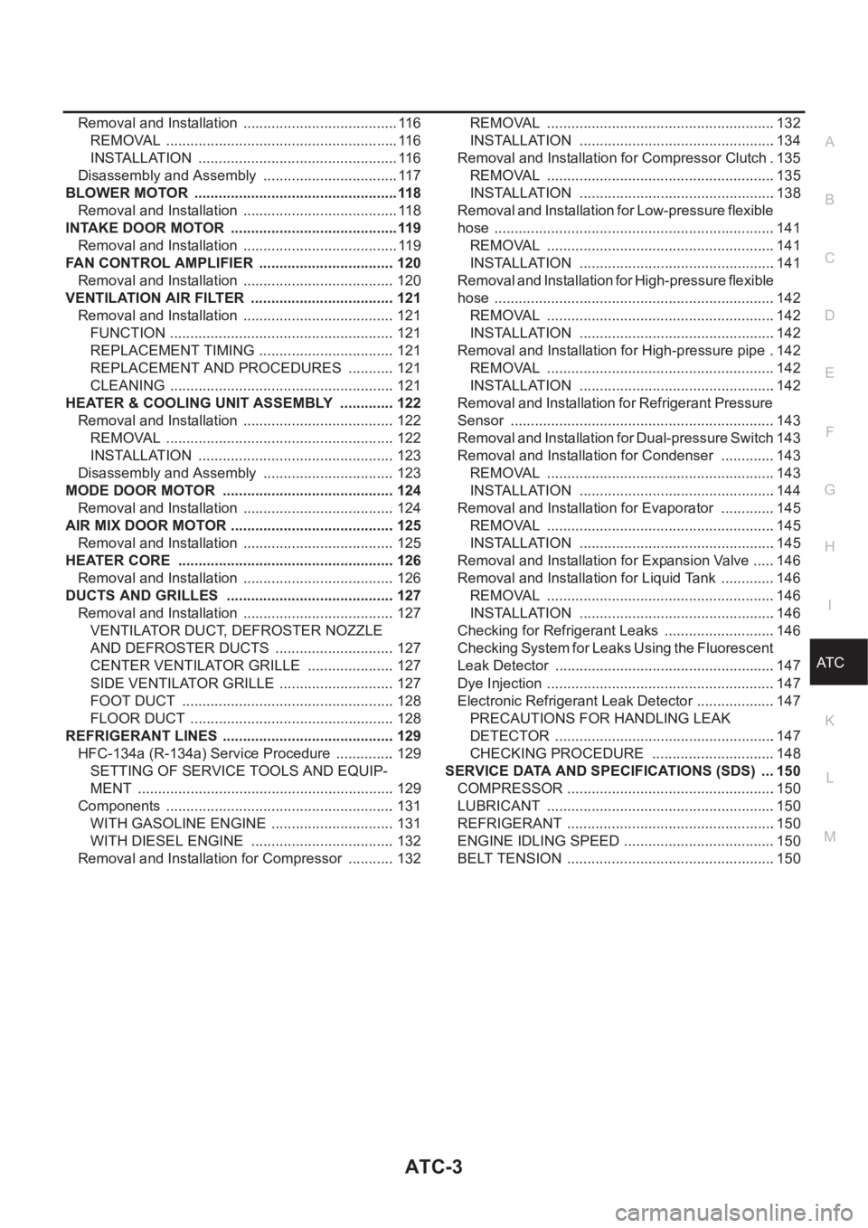
REFRIGERANT LINES ........................................... 129
HFC-134a (R-134a) Service Procedure ............... 129
SETTING OF SERVICE TOOLS AND EQUIP-
MENT ................................................................ 129
Components ......................................................... 131
WITH GASOLINE ENGINE ............................... 131
WITH DIESEL ENGINE .................................... 132
Removal and Installation for Compressor ............ 132REMOVAL .........................................................132
INSTALLATION .................................................134
Removal and Installation for Compressor Clutch . 135
REMOVAL .........................................................135
INSTALLATION .................................................138
Removal and Installation for Low-pressure flexible
hose ......................................................................141
REMOVAL .........................................................141
INSTALLATION .................................................141
Removal and Installation for High-pressure flexible
hose ......................................................................142
REMOVAL .........................................................142
INSTALLATION .................................................142
Removal and Installation for High-pressure pipe ..142
REMOVAL .........................................................142
INSTALLATION .................................................142
Removal and Installation for Refrigerant Pressure
Sensor ..................................................................143
Removal and Installation for Dual-pressure Switch .143
Removal and Installation for Condenser ..............143
REMOVAL .........................................................143
INSTALLATION .................................................144
Removal and Installation for Evaporator ..............145
REMOVAL .........................................................145
INSTALLATION .................................................145
Removal and Installation for Expansion Valve ......146
Removal and Installation for Liquid Tank ..............146
REMOVAL .........................................................146
INSTALLATION .................................................146
Checking for Refrigerant Leaks ............................146
Checking System for Leaks Using the Fluorescent
Leak Detector .......................................................147
Dye Injection .........................................................147
Electronic Refrigerant Leak Detector ....................147
PRECAUTIONS FOR HANDLING LEAK
DETECTOR .......................................................147
CHECKING PROCEDURE ...............................148
SERVICE DATA AND SPECIFICATIONS (SDS) ....150
COMPRESSOR ....................................................150
LUBRICANT .........................................................150
REFRIGERANT ....................................................150
ENGINE IDLING SPEED ......................................150
BELT TENSION ................................................... .150
Page 3281 of 3833
PRECAUTIONS
ATC-5
C
D
E
F
G
H
I
K
L
MA
B
AT C
General Refrigerant PrecautionsEJS000T2
WARNING:
●Do not release refrigerant into the air. Use approved recovery/recycling equipment to capture the
refrigerant every time an air conditioning system is discharged.
●Always wear eye and hand protection (goggles and gloves) when working with any refrigerant or
air conditioning system.
●Do not store or heat refrigerant containers above 52°C (125°F).
●Do not heat a refrigerant container with an open flame; if container warming is required, place the
bottom of the container in a warm pail of water.
●Do not intentionally drop, puncture, or incinerate refrigerant containers.
●Keep refrigerant away from open flames: poisonous gas will be produced if refrigerant burns.
●Refrigerant will displace oxygen, therefore be certain to work in well ventilated areas to prevent
suffocation.
●Do not pressure test or leak test HFC-134a (R-134a) service equipment and/or vehicle air condi-
tioning systems with compressed air during repair. Some mixtures of air and HFC-134a (R-134a)
have been shown to be combustible at elevated pressures. These mixtures, if ignited, may cause
injury or property damage. Additional health and safety information may be obtained from refriger-
ant manufacturers.
Lubricant PrecautionsEJS0027Y
●Use only specified lubricant for the HFC-134a (R-134a) A/C system and HFC-134a (R-134a) components.
If lubricant other than that specified is used, compressor malfunction is likely to occur.
●The specified HFC-134a (R-134a) lubricant rapidly absorbs moisture from the atmosphere. The following
handling precautions must be observed:
●When removing refrigerant components from a vehicle, immediately cap (seal) the component to minimize
the entry of moisture from the atmosphere.
●When installing refrigerant components to a vehicle, do not remove the caps (unseal) until just before con-
necting the components. Connect all refrigerant loop components as quickly as possible to minimize the
entry of moisture into system.
●Only use the specified lubricant from a sealed container. Immediately reseal containers of lubricant. With-
out proper sealing, lubricant will become moisture saturated and should not be used.
●Avoid breathing A/C refrigerant and lubricant vapor or mist. Exposure may irritate eyes, nose and throat.
Remove HFC-134a (R-134a) from the A/C system, using certified service equipment meeting require-
ments of SAE J2210 HFC-134a (R-134a) recycling equipment, or J2209 HFC-134a (R-134a) recovery
equipment. If accidental system discharge occurs, ventilate work area before resuming service. Additional
health and safety information may be obtained from refrigerant and lubricant manufacturers.
●Do not allow lubricant (Nissan A/C System Oil Type S or R) to come in contact with styrofoam parts. Dam-
age may result.
Precautions for Refrigerant ConnectionEJS000T4
A new type refrigerant connection has been introduced to all refrigerant lines except the following location.
●Expansion valve to cooling unit
●Refrigerant pressure sensor to liquid tank
Page 3294 of 3833
ATC-18
REFRIGERATION SYSTEM
REFRIGERATION SYSTEM
PFP:KA990
Refrigerant CycleEJS000TD
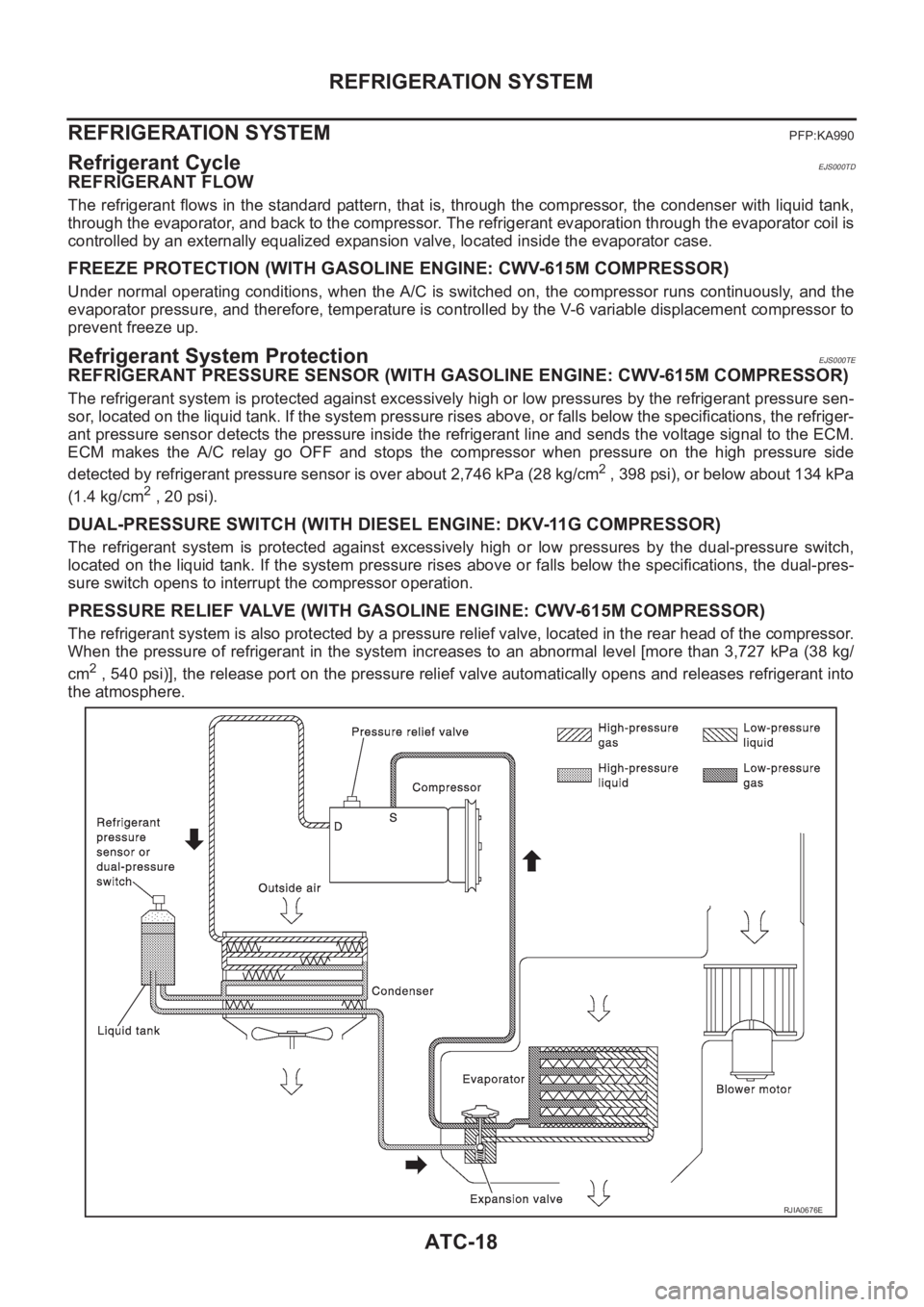
REFRIGERANT FLOW
The refrigerant flows in the standard pattern, that is, through the compressor, the condenser with liquid tank,
through the evaporator, and back to the compressor. The refrigerant evaporation through the evaporator coil is
controlled by an externally equalized expansion valve, located inside the evaporator case.
FREEZE PROTECTION (WITH GASOLINE ENGINE: CWV-615M COMPRESSOR)
Under normal operating conditions, when the A/C is switched on, the compressor runs continuously, and the
evaporator pressure, and therefore, temperature is controlled by the V-6 variable displacement compressor to
prevent freeze up.
Refrigerant System ProtectionEJS000TE
REFRIGERANT PRESSURE SENSOR (WITH GASOLINE ENGINE: CWV-615M COMPRESSOR)
The refrigerant system is protected against excessively high or low pressures by the refrigerant pressure sen-
sor, located on the liquid tank. If the system pressure rises above, or falls below the specifications, the refriger-
ant pressure sensor detects the pressure inside the refrigerant line and sends the voltage signal to the ECM.
ECM makes the A/C relay go OFF and stops the compressor when pressure on the high pressure side
detected by refrigerant pressure sensor is over about 2,746 kPa (28 kg/cm
2 , 398 psi), or below about 134 kPa
(1.4 kg/cm
2 , 20 psi).
DUAL-PRESSURE SWITCH (WITH DIESEL ENGINE: DKV-11G COMPRESSOR)
The refrigerant system is protected against excessively high or low pressures by the dual-pressure switch,
located on the liquid tank. If the system pressure rises above or falls below the specifications, the dual-pres-
sure switch opens to interrupt the compressor operation.
PRESSURE RELIEF VALVE (WITH GASOLINE ENGINE: CWV-615M COMPRESSOR)
The refrigerant system is also protected by a pressure relief valve, located in the rear head of the compressor.
When the pressure of refrigerant in the system increases to an abnormal level [more than 3,727 kPa (38 kg/
cm
2 , 540 psi)], the release port on the pressure relief valve automatically opens and releases refrigerant into
the atmosphere.
RJIA0676E
Page 3303 of 3833
AIR CONDITIONER CONTROL
ATC-27
C
D
E
F
G
H
I
K
L
MA
B
AT C
AIR CONDITIONER CONTROLPFP:27500
Overview Air Conditioner LAN Control SystemEJS000TI
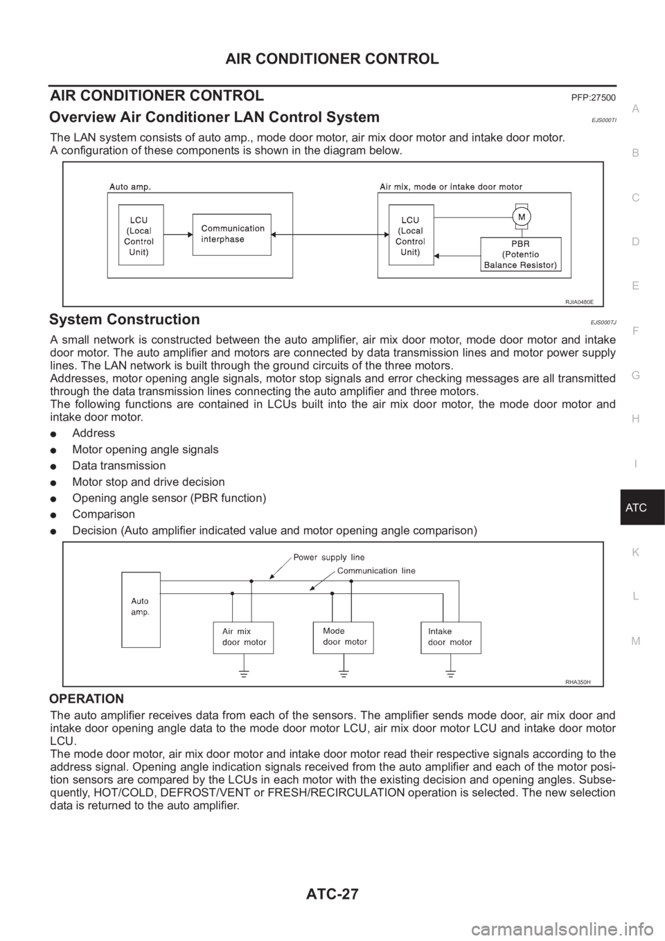
The LAN system consists of auto amp., mode door motor, air mix door motor and intake door motor.
A configuration of these components is shown in the diagram below.
System ConstructionEJS000TJ
A small network is constructed between the auto amplifier, air mix door motor, mode door motor and intake
door motor. The auto amplifier and motors are connected by data transmission lines and motor power supply
lines. The LAN network is built through the ground circuits of the three motors.
Addresses, motor opening angle signals, motor stop signals and error checking messages are all transmitted
through the data transmission lines connecting the auto amplifier and three motors.
The following functions are contained in LCUs built into the air mix door motor, the mode door motor and
intake door motor.
●Address
●Motor opening angle signals
●Data transmission
●Motor stop and drive decision
●Opening angle sensor (PBR function)
●Comparison
●Decision (Auto amplifier indicated value and motor opening angle comparison)
OPERATION
The auto amplifier receives data from each of the sensors. The amplifier sends mode door, air mix door and
intake door opening angle data to the mode door motor LCU, air mix door motor LCU and intake door motor
LCU.
The mode door motor, air mix door motor and intake door motor read their respective signals according to the
address signal. Opening angle indication signals received from the auto amplifier and each of the motor posi-
tion sensors are compared by the LCUs in each motor with the existing decision and opening angles. Subse-
quently, HOT/COLD, DEFROST/VENT or FRESH/RECIRCULATION operation is selected. The new selection
data is returned to the auto amplifier.
RJIA0480E
RHA350H
Page 3305 of 3833
AIR CONDITIONER CONTROL
ATC-29
C
D
E
F
G
H
I
K
L
MA
B
AT C
FAN SPEED CONTROL
Blower speed is automatically controlled based on temperature setting, ambient temperature, in-vehicle tem-
perature, intake temperature, amount of sunload and air mix door position.
With FAN switch set to AUTO, the blower motor starts to gradually increase air flow volume.
When engine coolant temperature is low, the blower motor operation is delayed to prevent cool air from flow-
ing.
INTAKE DOOR CONTROL
The intake doors are automatically controlled by: The temperature setting, ambient temperature, in-vehicle
temperature, intake temperature, amount of sunload and ON-OFF operation of the compressor.
OUTLET DOOR CONTROL
The outlet door is automatically controlled by: The temperature setting, ambient temperature, in-vehicle tem-
perature, intake temperature and amount of sunload.
MAGNET CLUTCH CONTROL
The ECM controls compressor operation using input signals from the throttle position sensor and auto ampli-
fier.
SELF-DIAGNOSTIC SYSTEM
The self-diagnostic system is built into the auto amplifier (LCU) to quickly locate the cause of malfunctions.
Overview of Control systemEJS000TK
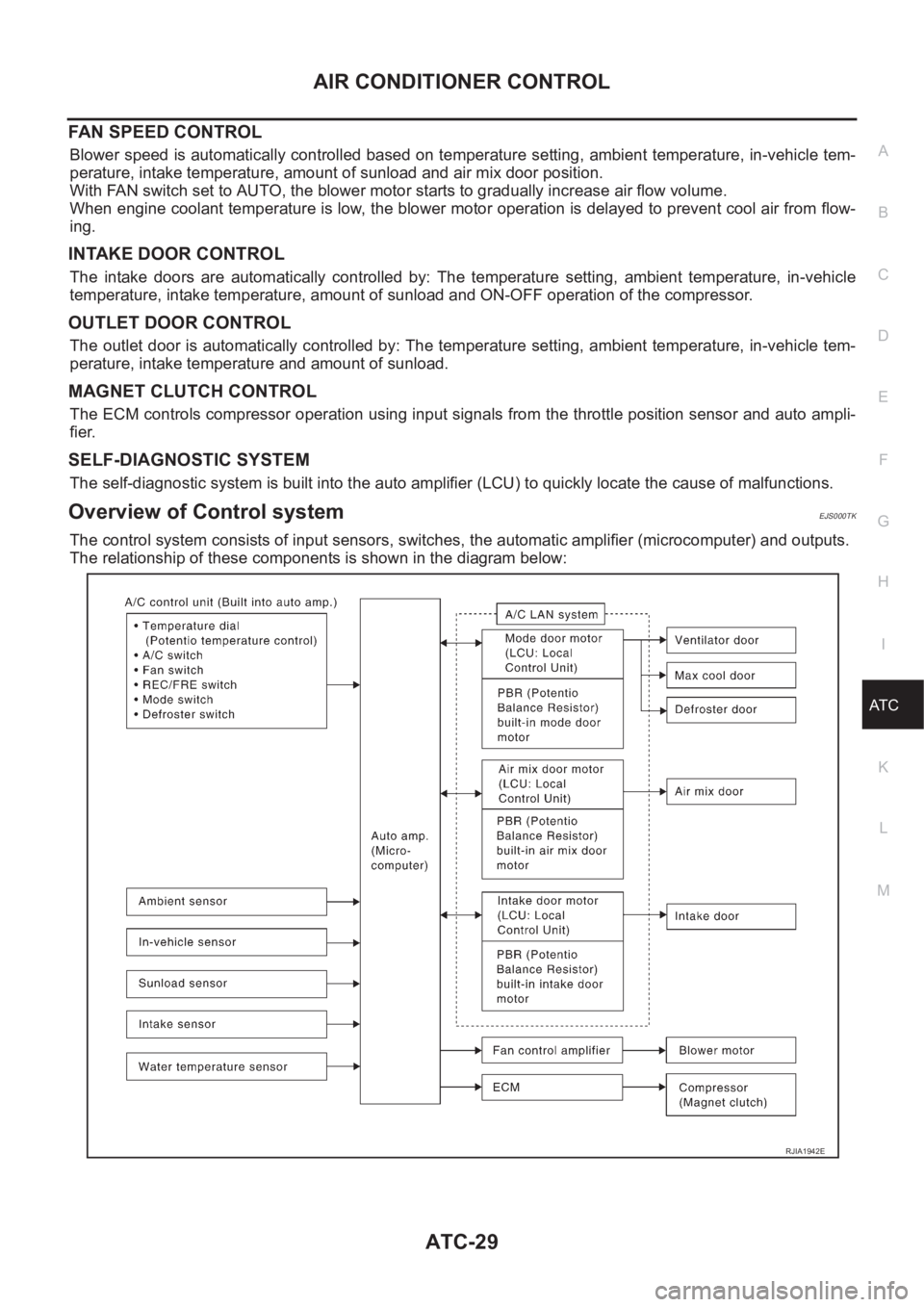
The control system consists of input sensors, switches, the automatic amplifier (microcomputer) and outputs.
The relationship of these components is shown in the diagram below:
RJIA1942E