2001 NISSAN X-TRAIL sensor
[x] Cancel search: sensorPage 3053 of 3833

BL-1
BODY, LOCK & SECURITY SYSTEM
I BODY
CONTENTS
C
D
E
F
G
H
J
K
L
M
SECTION
A
B
BL
BODY, LOCK & SECURITY SYSTEM
PRECAUTIONS .......................................................... 3
Precautions for Supplemental Restraint System
(SRS) “AIR BAG” and “SEAT BELT PRE-TEN-
SIONER” .................................................................. 3
Precautions .............................................................. 3
HOOD ......................................................................... 4
Fitting Adjustment .................................................... 4
FRONT END HEIGHT ADJUSTMENT AND LAT-
ERAL/LONGITUDINAL CLEARANCE ADJUST-
MENT .................................................................... 4
SURFACE HEIGHT ADJUSTMENT ..................... 4
Removal and Installation of Hood Assembly ............ 5
Removal and Installation of Hood Lock Control ....... 6
REMOVAL ............................................................. 6
INSTALLATION ..................................................... 7
Hood Lock Control Inspection .................................. 7
DOOR ......................................................................... 8
Fitting Adjustment .................................................... 8
FRONT DOOR ...................................................... 8
REAR DOOR ........................................................ 8
STRIKER ADJUSTMENT ..................................... 8
Removal and Installation .......................................... 9
Door Weatherstrip .................................................. 10
POWER DOOR LOCK SYSTEM ...............................11
System Description ................................................. 11
OPERATION ........................................................ 11
Component Parts and Harness Connector Location .... 11
Schematic .............................................................. 12
Wiring Diagram — D/LOCK — ............................... 13
Terminal and Reference Value for Time Control Unit ... 17
Symptom Chart ...................................................... 18
Power Supply and Ground Circuit Check ............... 18
Door Lock/Unlock Switch Check ............................ 19
Door Key Cylinder Switch Check ........................... 20
Front Door Lock Actuator (Driver Side) Check ....... 21
Front Door Lock Actuator (Passenger Side) Check ... 22
Rear Door Lock Actuator LH Check ....................... 23
Rear Door Lock Actuator RH Check ...................... 24
Back Door Lock Actuator Check ............................ 25
Door Switch Check ................................................. 26Door Unlock Sensor Check .................................... 26
Key Switch Check ................................................... 27
POWER DOOR LOCK — SUPER LOCK — ............ 29
System Description ................................................. 29
OUTLINE ............................................................. 29
OPERATION .....................................................
... 29
Schematic ............................................................... 31
Wiring Diagram — S/LOCK — ............................... 32
Terminal and Reference Value for Time Control Unit ... 38
Trouble Diagnoses ................................................. 39
PRELIMINARY CHECK ....................................... 39
SYMPTOM CHART ............................................. 40
Power Supply and Ground Circuit Check ............... 41
Door Lock/Unlock Switch Check ............................ 42
Door Key Cylinder Switch Check ............................ 43
Front Door Lock Actuator (Driver Side) Check ....... 44
Front Door Lock Actuator (Passenger Side) Check ... 45
Rear Door Lock Actuator LH Check ....................... 46
Rear Door Lock Actuator RH Check ....................... 47
Back Door Lock Actuator Check ............................. 48
Door Switch Check ................................................. 49
Door Unlock Sensor Check .................................... 50
Key Switch Check ................................................... 51
Super Lock Actuator Check .................................... 52
NATS Release Signal Check .................................. 53
Ignition Switch “ON” Circuit Check ......................... 54
MULTI-REMOTE CONTROL SYSTEM ..................... 55
Component Parts and Harness Connector Location ... 55
System Description ................................................. 56
FUNCTION .......................................................... 56
LOCK OPERATION ............................................. 56
UNLOCK OPERATION ........................................ 56
HAZARD REMINDER ......................................... 56
MULTI-REMOTE CONTROLLER ID CODE
ENTRY ................................................................ 56
Wiring Diagram — MULTI — .................................. 57
Terminal and Reference Value for Multi-remote
Control Unit ............................................................. 59
Symptom Chart ....................................................... 59
Remote Controller Battery Check ........................... 59
Page 3063 of 3833
POWER DOOR LOCK SYSTEM
BL-11
C
D
E
F
G
H
J
K
L
MA
B
BL
POWER DOOR LOCK SYSTEMPFP:24814
System DescriptionEIS001SE
OPERATION
Power door lock/unlock operation by door key cylinder
●With the key inserted into driver's door key cylinder, turning it to LOCK will lock all doors.
●With the key inserted into driver's door key cylinder, turning it to UNLOCK will unlock all doors.
Power door lock/unlock operation by lock/unlock switch
●With lock/unlock switch setting to LOCK will lock all doors.
●With lock/unlock switch setting to UNLOCK will unlock all doors.
Key reminder system
●If the ignition key is in the ignition key cylinder and driver door is open, setting lock/unlock switch, lock
knob, key or multi-remote controller to “LOCK” locks the door once but then immediately unlocks all doors.
(signal from door unlock sensor driver side)
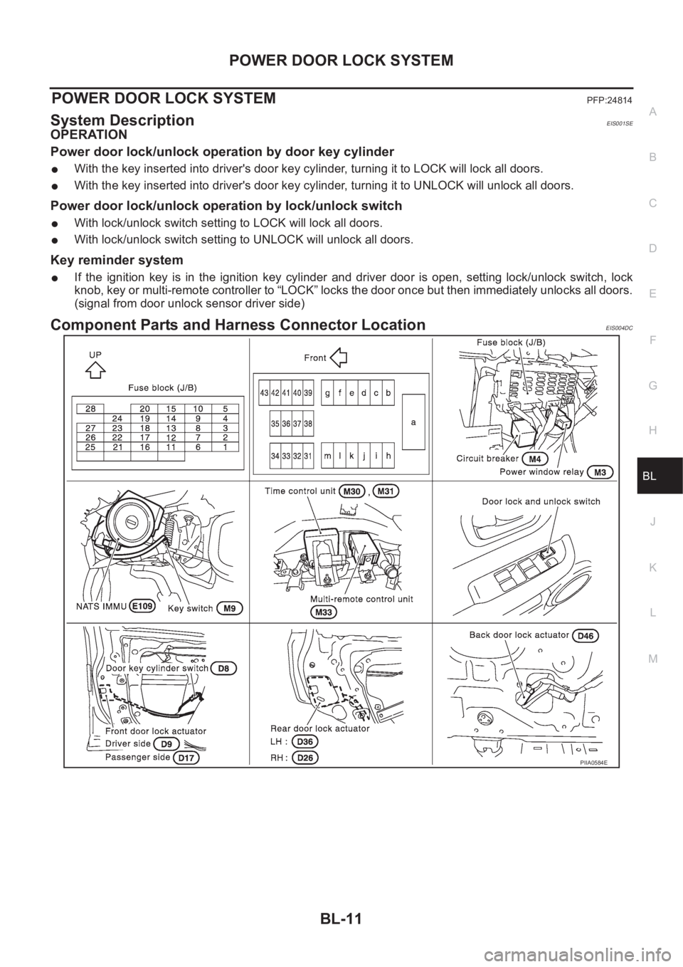
Component Parts and Harness Connector LocationEIS004DC
PIIA0584E
Page 3070 of 3833
BL-18
POWER DOOR LOCK SYSTEM
Symptom Chart
EIS001R5
*:Make sure the power door lock system operates properly.
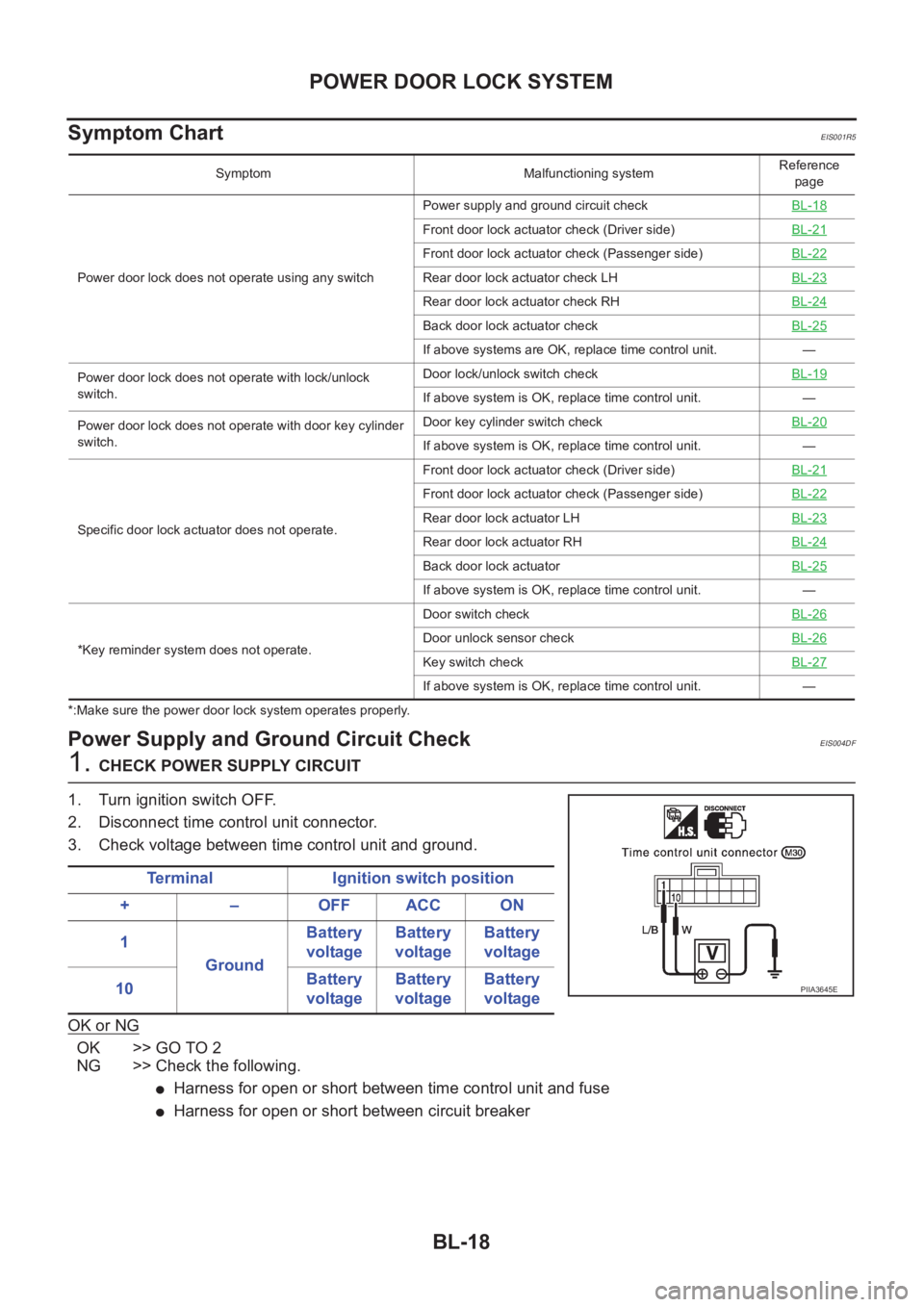
Power Supply and Ground Circuit CheckEIS004DF
1. CHECK POWER SUPPLY CIRCUIT
1. Turn ignition switch OFF.
2. Disconnect time control unit connector.
3. Check voltage between time control unit and ground.
OK or NG
OK >> GO TO 2
NG >> Check the following.
●Harness for open or short between time control unit and fuse
●Harness for open or short between circuit breaker
Symptom Malfunctioning systemReference
page
Power door lock does not operate using any switchPower supply and ground circuit checkBL-18
Front door lock actuator check (Driver side)BL-21
Front door lock actuator check (Passenger side)BL-22
Rear door lock actuator check LH BL-23
Rear door lock actuator check RHBL-24
Back door lock actuator checkBL-25
If above systems are OK, replace time control unit. —
Power door lock does not operate with lock/unlock
switch.Door lock/unlock switch checkBL-19
If above system is OK, replace time control unit. —
Power door lock does not operate with door key cylinder
switch.Door key cylinder switch checkBL-20
If above system is OK, replace time control unit. —
Specific door lock actuator does not operate.Front door lock actuator check (Driver side)BL-21
Front door lock actuator check (Passenger side)BL-22
Rear door lock actuator LHBL-23
Rear door lock actuator RHBL-24
Back door lock actuatorBL-25
If above system is OK, replace time control unit. —
*Key reminder system does not operate.Door switch checkBL-26
Door unlock sensor checkBL-26
Key switch checkBL-27
If above system is OK, replace time control unit. —
Terminal Ignition switch position
+ – OFF ACC ON
1
GroundBattery
voltageBattery
voltageBattery
voltage
10Battery
voltageBattery
voltageBattery
voltage
PIIA3645E
Page 3078 of 3833
BL-26
POWER DOOR LOCK SYSTEM
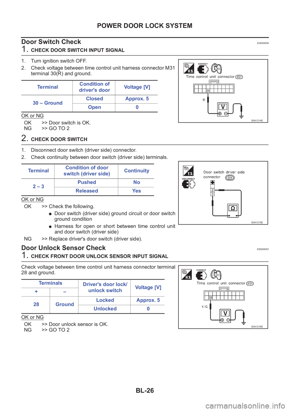
Door Switch Check
EIS004DN
1. CHECK DOOR SWITCH INPUT SIGNAL
1. Turn ignition switch OFF.
2. Check voltage between time control unit harness connector M31
terminal 30(R) and ground.
OK or NG
OK >> Door switch is OK.
NG >> GO TO 2
2. CHECK DOOR SWITCH
1. Disconnect door switch (driver side) connector.
2. Check continuity between door switch (driver side) terminals.
OK or NG
OK >> Check the following.
●Door switch (driver side) ground circuit or door switch
ground condition
●Harness for open or short between time control unit
and door switch (driver side)
NG >> Replace driver's door switch (driver side).
Door Unlock Sensor CheckEIS004DO
1. CHECK FRONT DOOR UNLOCK SENSOR INPUT SIGNAL
Check voltage between time control unit harness connector terminal
28 and ground.
OK or NG
OK >> Door unlock sensor is OK.
NG >> GO TO 2Te r m i n a lCondition of
driver's doorVoltage [V]
30 – GroundClosed Approx. 5
Open 0
SIIA1214E
Te r m i n a lCondition of door
switch (driver side)Continuity
2 – 3Pushed No
Released Yes
SIIA1215E
Te r m i n a l s
Driver's door lock/
unlock switchVoltage [V]
+–
28 GroundLocked Approx. 5
Unlocked 0
SIIA1216E
Page 3079 of 3833
POWER DOOR LOCK SYSTEM
BL-27
C
D
E
F
G
H
J
K
L
MA
B
BL
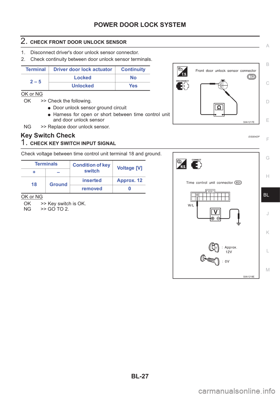
2.CHECK FRONT DOOR UNLOCK SENSOR
1. Disconnect driver's door unlock sensor connector.
2. Check continuity between door unlock sensor terminals.
OK or NG
OK >> Check the following.
●Door unlock sensor ground circuit
●Harness for open or short between time control unit
and door unlock sensor
NG >> Replace door unlock sensor.
Key Switch CheckEIS004DP
1.CHECK KEY SWITCH INPUT SIGNAL
Check voltage between time control unit terminal 18 and ground.
OK or NG
OK >> Key switch is OK.
NG >> GO TO 2.Terminal Driver door lock actuator Continuity
2 – 5Locked No
Unlocked Yes
SIIA1217E
Te r m i n a l s
Condition of key
switchVo l ta g e [ V ]
+–
18 Groundinserted Approx. 12
removed 0
SIIA1218E
Page 3082 of 3833
BL-30
POWER DOOR LOCK — SUPER LOCK —
Key reminder system
●If the ignition key is in the ignition key cylinder and driver door is open, setting lock/unlock switch, lock
knob, key or multi-remote controller to “LOCK” locks the door once but then immediately unlocks all doors.
(signal from door unlock sensor driver side)
System initialization
●System initialization is required when battery cables are reconnected. Conduct the following to release
super lock once;
– insert the key into the ignition key cylinder and turn it to ON.
– LOCK/UNLOCK operation using door key cylinder or multi-remote controller.
Page 3092 of 3833
BL-40
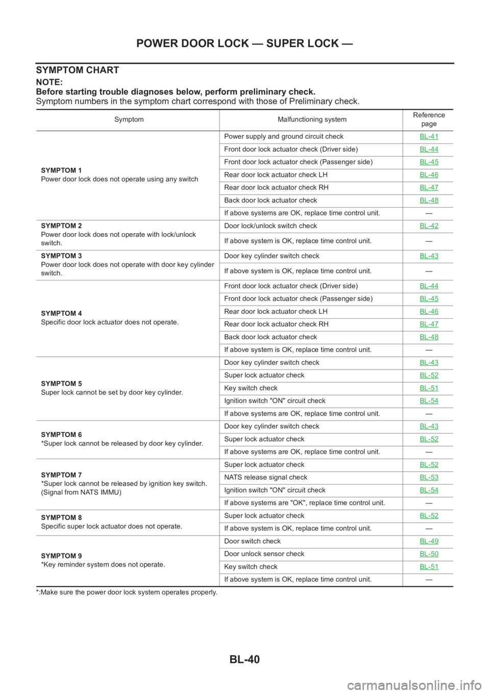
POWER DOOR LOCK — SUPER LOCK —
SYMPTOM CHART
NOTE:
Before starting trouble diagnoses below, perform preliminary check.
Symptom numbers in the symptom chart correspond with those of Preliminary check.
*:Make sure the power door lock system operates properly.Symptom Malfunctioning systemReference
page
SYMPTOM 1
Power door lock does not operate using any switchPower supply and ground circuit checkBL-41
Front door lock actuator check (Driver side)BL-44
Front door lock actuator check (Passenger side)BL-45
Rear door lock actuator check LH BL-46
Rear door lock actuator check RHBL-47
Back door lock actuator checkBL-48
If above systems are OK, replace time control unit. —
SYMPTOM 2
Power door lock does not operate with lock/unlock
switch.Door lock/unlock switch checkBL-42
If above system is OK, replace time control unit. —
SYMPTOM 3
Power door lock does not operate with door key cylinder
switch.Door key cylinder switch checkBL-43
If above system is OK, replace time control unit. —
SYMPTOM 4
Specific door lock actuator does not operate.Front door lock actuator check (Driver side)BL-44
Front door lock actuator check (Passenger side)BL-45
Rear door lock actuator check LH BL-46
Rear door lock actuator check RHBL-47
Back door lock actuator checkBL-48
If above system is OK, replace time control unit. —
SYMPTOM 5
Super lock cannot be set by door key cylinder.Door key cylinder switch checkBL-43
Super lock actuator checkBL-52
Key switch checkBL-51
Ignition switch "ON" circuit checkBL-54
If above systems are OK, replace time control unit. —
SYMPTOM 6
*Super lock cannot be released by door key cylinder.Door key cylinder switch checkBL-43
Super lock actuator checkBL-52
If above systems are OK, replace time control unit. —
SYMPTOM 7
*Super lock cannot be released by ignition key switch.
(Signal from NATS IMMU)Super lock actuator checkBL-52
NATS release signal checkBL-53
Ignition switch "ON" circuit checkBL-54
If above systems are "OK", replace time control unit. —
SYMPTOM 8
Specific super lock actuator does not operate.Super lock actuator checkBL-52
If above system is OK, replace time control unit. —
SYMPTOM 9
*Key reminder system does not operate.Door switch checkBL-49
Door unlock sensor checkBL-50
Key switch checkBL-51
If above system is OK, replace time control unit. —
Page 3102 of 3833
BL-50
POWER DOOR LOCK — SUPER LOCK —
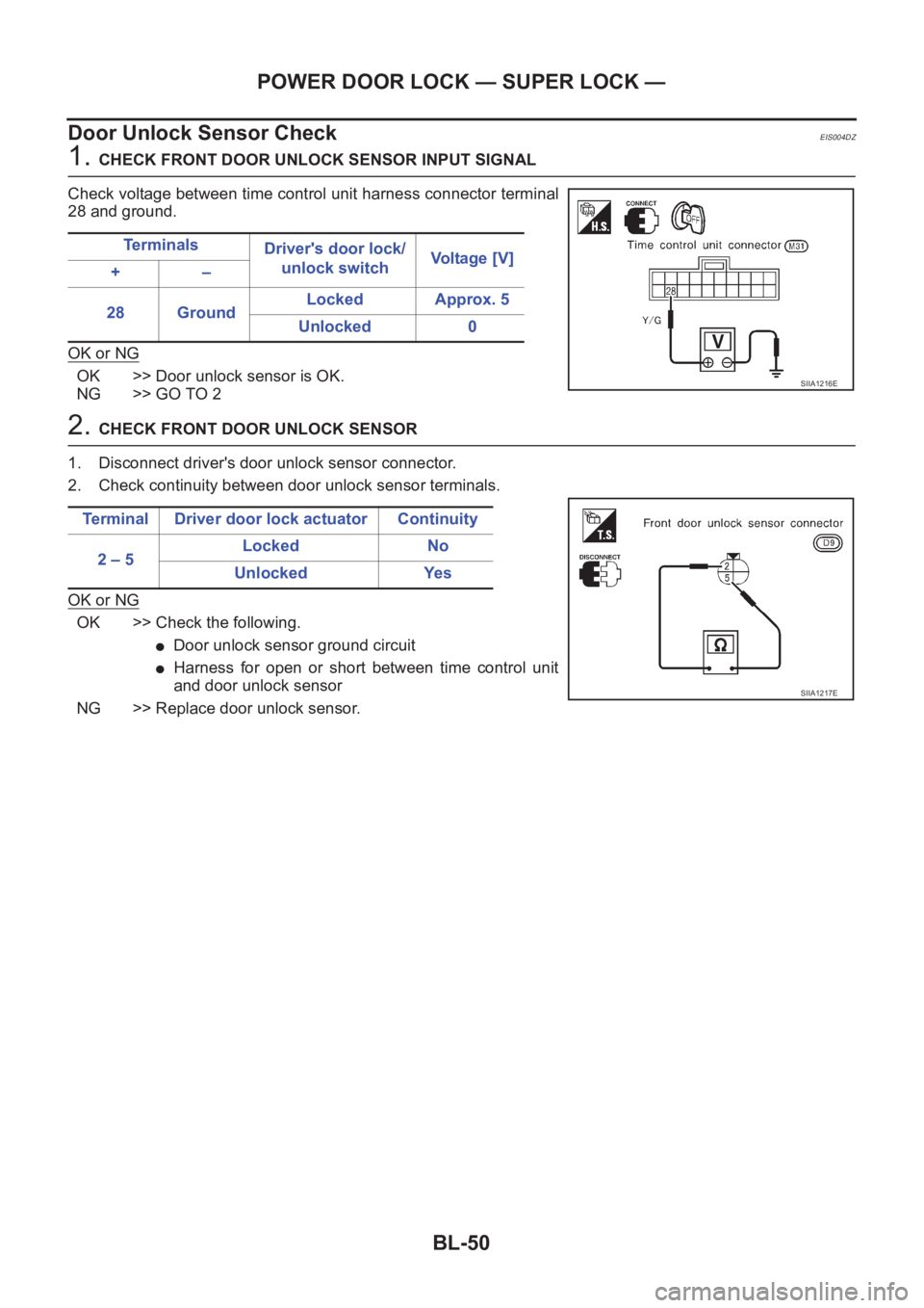
Door Unlock Sensor Check
EIS004DZ
1. CHECK FRONT DOOR UNLOCK SENSOR INPUT SIGNAL
Check voltage between time control unit harness connector terminal
28 and ground.
OK or NG
OK >> Door unlock sensor is OK.
NG >> GO TO 2
2. CHECK FRONT DOOR UNLOCK SENSOR
1. Disconnect driver's door unlock sensor connector.
2. Check continuity between door unlock sensor terminals.
OK or NG
OK >> Check the following.
●Door unlock sensor ground circuit
●Harness for open or short between time control unit
and door unlock sensor
NG >> Replace door unlock sensor.Te r m i n a l s
Driver's door lock/
unlock switchVoltage [V]
+–
28 GroundLocked Approx. 5
Unlocked 0
SIIA1216E
Terminal Driver door lock actuator Continuity
2 – 5Locked No
Unlocked Yes
SIIA1217E