Page 3338 of 3833
ATC-62
TROUBLE DIAGNOSIS
Mode Door Motor Circuit
EJS002FP
SYMPTOM:
●Air outlet does not change.
●Mode door motor does not operate normally.
INSPECTION FLOW
*1ATC-31, "Discharge Air Flow".*2AT C - 5 4 , "Operational Check".*3ATC-47, "PROCEDURE", see No.
1.
*4ATC-47, "
PROCEDURE", see No. 5
to 7.*5ATC-100, "Ambient Sensor Circuit".*6ATC-102, "In-vehicle Sensor Cir-
cuit".
*7ATC-105, "
Sunload Sensor Circuit".*8AT C - 6 4 , "Air Mix Door Motor Circuit".*9ATC-47, "PROCEDURE", see No.
14.
*10ATC-59, "
LAN System Circuit".*11ATC-124, "MODE DOOR MOTOR".*12ATC-54, "Operational Check".
*13ATC-33, "
SYMPTOM TABLE".*14ATC-108, "Intake Sensor Circuit".
RJIA0512E
Page 3339 of 3833

TROUBLE DIAGNOSIS
ATC-63
C
D
E
F
G
H
I
K
L
MA
B
AT C
SYSTEM DESCRIPTION
Component Parts
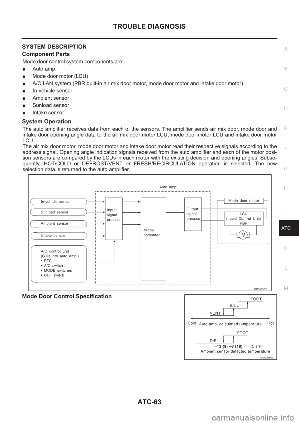
Mode door control system components are:
●Auto amp.
●Mode door motor (LCU)
●A/C LAN system (PBR built-in air mix door motor, mode door motor and intake door motor)
●In-vehicle sensor
●Ambient sensor
●Sunload sensor
●Intake sensor
System Operation
The auto amplifier receives data from each of the sensors. The amplifier sends air mix door, mode door and
intake door opening angle data to the air mix door motor LCU, mode door motor LCU and intake door motor
LCU.
The air mix door motor, mode door motor and intake door motor read their respective signals according to the
address signal. Opening angle indication signals received from the auto amplifier and each of the motor posi-
tion sensors are compared by the LCUs in each motor with the existing decision and opening angles. Subse-
quently, HOT/COLD or DEFROST/VENT or FRESH/RECIRCULATION operation is selected. The new
selection data is returned to the auto amplifier.
Mode Door Control Specification
RHA045HA
RHA384HA
Page 3341 of 3833
TROUBLE DIAGNOSIS
ATC-65
C
D
E
F
G
H
I
K
L
MA
B
AT C
INSPECTION FLOW
*1ATC-47, "PROCEDURE", see No.1 *2ATC-100, "Ambient Sensor Circuit".*3ATC-102, "In-vehicle Sensor Circuit".
*4ATC-105, "
Sunload Sensor Circuit".*5ATC-64, "Air Mix Door Motor Circuit".*6ATC-47, "PROCEDURE", see No.
14.
*7ATC-59, "
LAN System Circuit".*8ATC-54, "Operational Check".*9ATC-54, "Operational Check".
*10ATC-33, "
SYMPTOM TABLE".*11ATC-108, "Intake Sensor Circuit".*12ATC-47, "PROCEDURE", see No. 5
to 7.
RJIA0515E
Page 3342 of 3833

ATC-66
TROUBLE DIAGNOSIS
SYSTEM DESCRIPTION
Component Parts
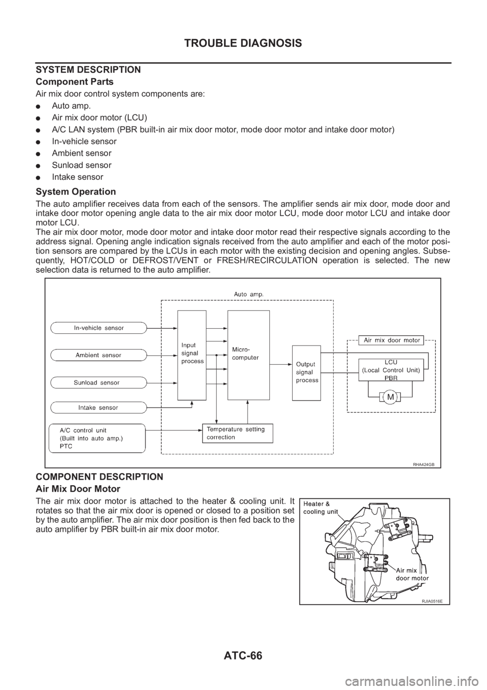
Air mix door control system components are:
●Auto amp.
●Air mix door motor (LCU)
●A/C LAN system (PBR built-in air mix door motor, mode door motor and intake door motor)
●In-vehicle sensor
●Ambient sensor
●Sunload sensor
●Intake sensor
System Operation
The auto amplifier receives data from each of the sensors. The amplifier sends air mix door, mode door and
intake door motor opening angle data to the air mix door motor LCU, mode door motor LCU and intake door
motor LCU.
The air mix door motor, mode door motor and intake door motor read their respective signals according to the
address signal. Opening angle indication signals received from the auto amplifier and each of the motor posi-
tion sensors are compared by the LCUs in each motor with the existing decision and opening angles. Subse-
quently, HOT/COLD or DEFROST/VENT or FRESH/RECIRCULATION operation is selected. The new
selection data is returned to the auto amplifier.
COMPONENT DESCRIPTION
Air Mix Door Motor
The air mix door motor is attached to the heater & cooling unit. It
rotates so that the air mix door is opened or closed to a position set
by the auto amplifier. The air mix door position is then fed back to the
auto amplifier by PBR built-in air mix door motor.
RHA424GB
RJIA0516E
Page 3344 of 3833
ATC-68
TROUBLE DIAGNOSIS
Intake Door Motor Circuit
EJS001H3
SYMPTOM:
●Intake door does not change.
●Intake door motor does not operate normally.
INSPECTION FLOW
*1AT C - 9 8 , "Self-diagnosis", see No.1 *2ATC-100, "Ambient Sensor Circuit".*3ATC-102, "In-vehicle Sensor Cir-
cuit".
*4AT C - 1 0 5 , "
Sunload Sensor Circuit".*5ATC-64, "Air Mix Door Motor Circuit".*6ATC-47, "PROCEDURE", see No.
14.
*7AT C - 5 9 , "
LAN System Circuit".*8ATC-119, "INTAKE DOOR MOTOR".*9ATC-54, "Operational Check".
*10AT C - 4 7 , "
PROCEDURE", see No. 5
to 7.*11ATC-54, "Operational Check".*12ATC-33, "SYMPTOM TABLE".
*13ATC-108, "
Intake Sensor Circuit".
RJIA0518E
Page 3345 of 3833

TROUBLE DIAGNOSIS
ATC-69
C
D
E
F
G
H
I
K
L
MA
B
AT C
SYSTEM DESCRIPTION
Component Parts
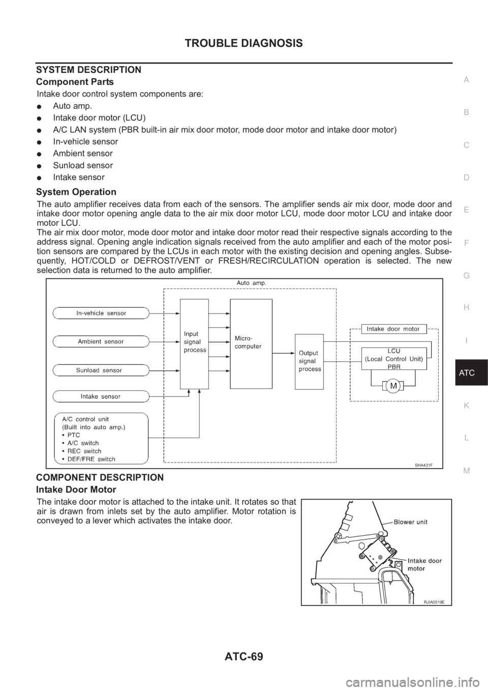
Intake door control system components are:
●Auto amp.
●Intake door motor (LCU)
●A/C LAN system (PBR built-in air mix door motor, mode door motor and intake door motor)
●In-vehicle sensor
●Ambient sensor
●Sunload sensor
●Intake sensor
System Operation
The auto amplifier receives data from each of the sensors. The amplifier sends air mix door, mode door and
intake door motor opening angle data to the air mix door motor LCU, mode door motor LCU and intake door
motor LCU.
The air mix door motor, mode door motor and intake door motor read their respective signals according to the
address signal. Opening angle indication signals received from the auto amplifier and each of the motor posi-
tion sensors are compared by the LCUs in each motor with the existing decision and opening angles. Subse-
quently, HOT/COLD or DEFROST/VENT or FRESH/RECIRCULATION operation is selected. The new
selection data is returned to the auto amplifier.
COMPONENT DESCRIPTION
Intake Door Motor
The intake door motor is attached to the intake unit. It rotates so that
air is drawn from inlets set by the auto amplifier. Motor rotation is
conveyed to a lever which activates the intake door.
SHA431F
RJIA0519E
Page 3347 of 3833
TROUBLE DIAGNOSIS
ATC-71
C
D
E
F
G
H
I
K
L
MA
B
AT C
INSPECTION FLOW
*1ATC-47, "PROCEDURE".*2ATC-100, "Ambient Sensor Circuit".*3ATC-102, "In-vehicle Sensor Circuit".
*4ATC-105, "
Sunload Sensor Circuit".*5ATC-64, "Air Mix Door Motor Circuit".*6ATC-47, "PROCEDURE",see No. 13.
*7ATC-70, "
Blower Motor Circuit".*8ATC-47, "PROCEDURE" see 5 to 7. *9ATC-54, "Operational Check".
RJIA0521E
Page 3348 of 3833

ATC-72
TROUBLE DIAGNOSIS
SYSTEM DESCRIPTION
Component Parts
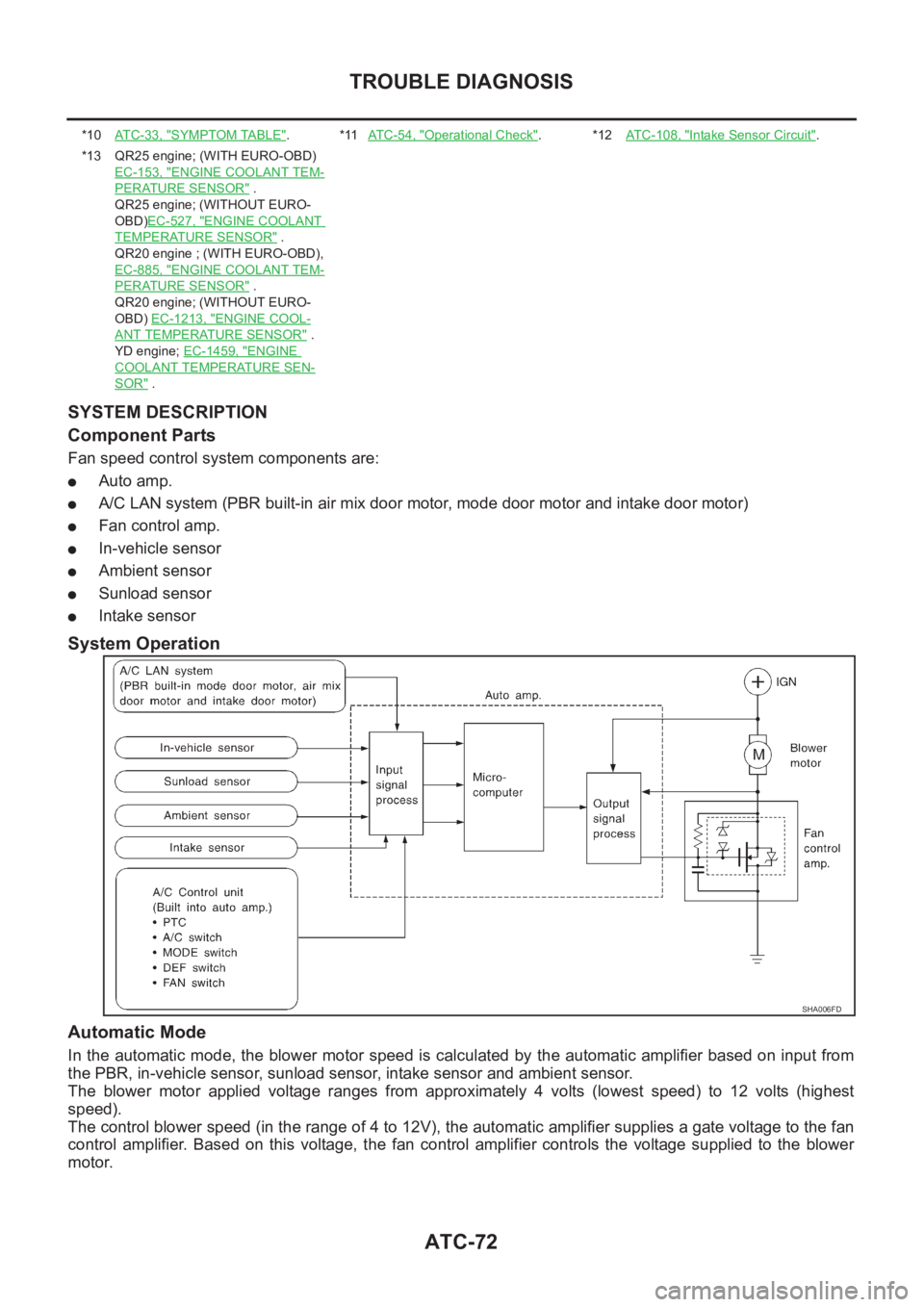
Fan speed control system components are:
●Auto amp.
●A/C LAN system (PBR built-in air mix door motor, mode door motor and intake door motor)
●Fan control amp.
●In-vehicle sensor
●Ambient sensor
●Sunload sensor
●Intake sensor
System Operation
Automatic Mode
In the automatic mode, the blower motor speed is calculated by the automatic amplifier based on input from
the PBR, in-vehicle sensor, sunload sensor, intake sensor and ambient sensor.
The blower motor applied voltage ranges from approximately 4 volts (lowest speed) to 12 volts (highest
speed).
The control blower speed (in the range of 4 to 12V), the automatic amplifier supplies a gate voltage to the fan
control amplifier. Based on this voltage, the fan control amplifier controls the voltage supplied to the blower
motor.
*10AT C - 3 3 , "SYMPTOM TABLE".*11AT C - 5 4 , "Operational Check".*12ATC-108, "Intake Sensor Circuit".
*13 QR25 engine; (WITH EURO-OBD)
EC-153, "
ENGINE COOLANT TEM-
PERATURE SENSOR" .
QR25 engine; (WITHOUT EURO-
OBD)EC-527, "
ENGINE COOLANT
TEMPERATURE SENSOR" .
QR20 engine ; (WITH EURO-OBD),
EC-885, "
ENGINE COOLANT TEM-
PERATURE SENSOR" .
QR20 engine; (WITHOUT EURO-
OBD) EC-1213, "
ENGINE COOL-
ANT TEMPERATURE SENSOR" .
YD engine; EC-1459, "
ENGINE
COOLANT TEMPERATURE SEN-
SOR" .
SHA006FD