Page 3575 of 3833
COMBINATION METERS (LHD MODELS)
DI-17
C
D
E
F
G
H
I
J
L
MA
B
DI
Inspection/Fuel Level Sensor UnitEKS002ZI
FUEL LEVEL SENSOR UNIT
The following symptoms do not indicate a malfunction.
●Depending on vehicle posture or driving circumstance, the fuel level in the tank varies, and the pointer
may fluctuate.
●If the vehicle is fueled with the ignition switch ON, the pointer will move slowly.
LOW-FUEL WARNING LAMP
Depending on vehicle posture or driving circumstance, the fuel level in the tank varies, and the warning lamp
ON timing may be changed.
1.DIAGNOSIS MODE INSPECTION
Preform the combination meter diagnosis mode. Refer to DI-10, "
Meter/Gauge Operation and Odo/Trip Meter
Segment Check in Diagnosis Mode" .
OK or NG
OK >> GO TO 2.
NG >> Replace combination meter.
2.HARNESS CONNECTOR INSPECTION
1. Turn the ignition switch OFF.
2. Check combination meter, fuel level sensor unit and terminals (meter-side, module-side, and harness-
side) for poor connection and bend.
OK or NG
OK >> GO TO 3.
NG >> Repair or replace terminals or connectors.
3.CHECK FUEL LEVEL SENSOR FOR OPEN CIRCUIT
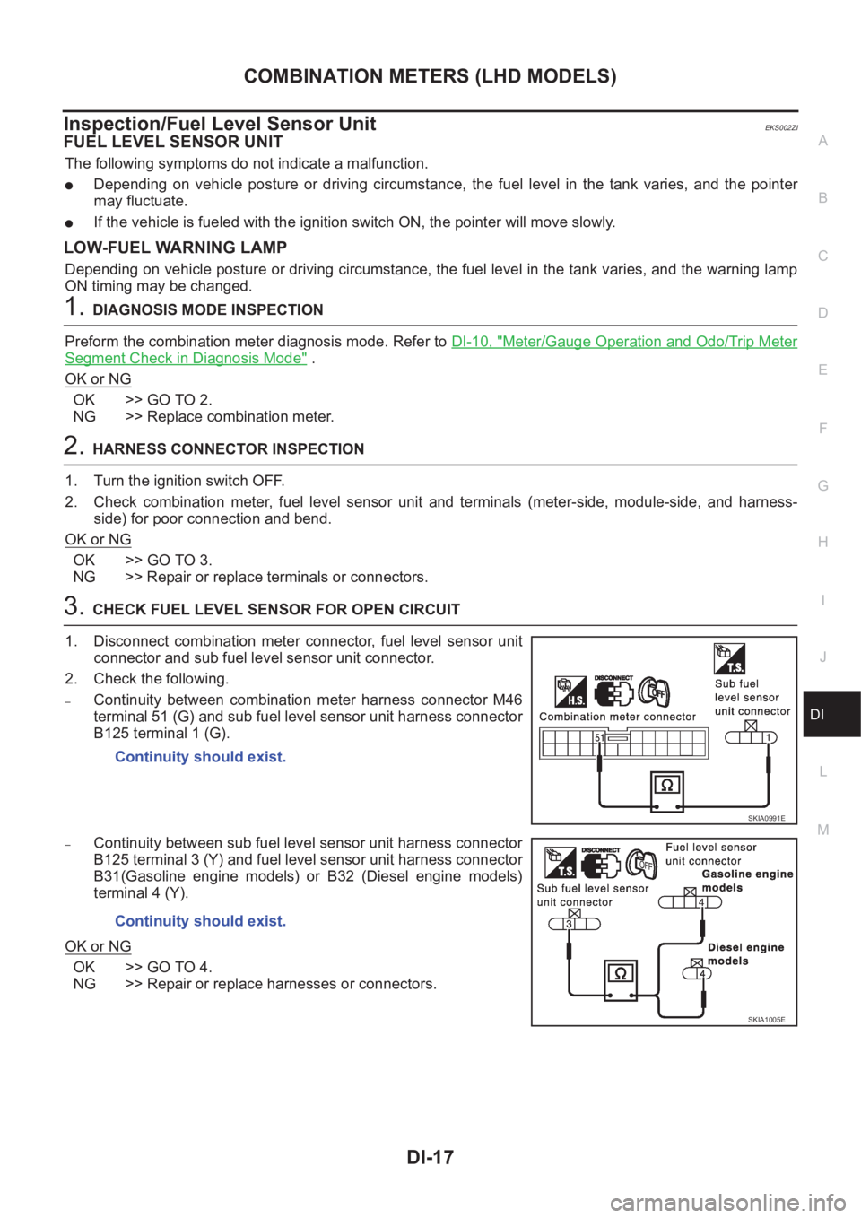
1. Disconnect combination meter connector, fuel level sensor unit
connector and sub fuel level sensor unit connector.
2. Check the following.
–Continuity between combination meter harness connector M46
terminal 51 (G) and sub fuel level sensor unit harness connector
B125 terminal 1 (G).
–Continuity between sub fuel level sensor unit harness connector
B125 terminal 3 (Y) and fuel level sensor unit harness connector
B31(Gasoline engine models) or B32 (Diesel engine models)
terminal 4 (Y).
OK or NG
OK >> GO TO 4.
NG >> Repair or replace harnesses or connectors.Continuity should exist.
SKIA0991E
Continuity should exist.
SKIA1005E
Page 3576 of 3833
DI-18
COMBINATION METERS (LHD MODELS)
4. CHECK FUEL LEVEL SENSOR SHORT CIRCUIT
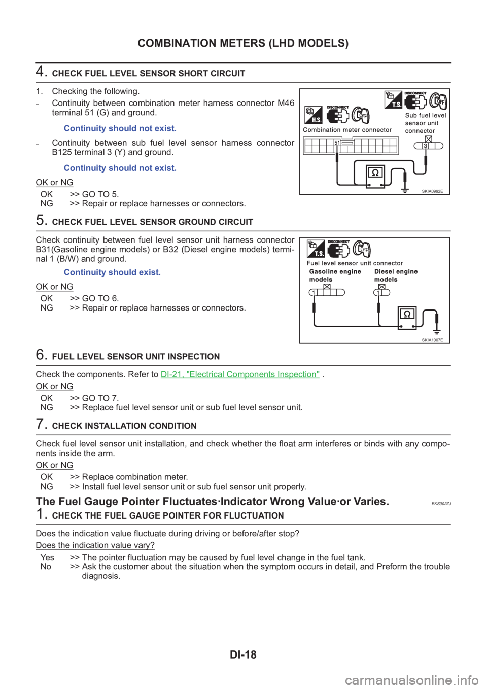
1. Checking the following.
–Continuity between combination meter harness connector M46
terminal 51 (G) and ground.
–Continuity between sub fuel level sensor harness connector
B125 terminal 3 (Y) and ground.
OK or NG
OK >> GO TO 5.
NG >> Repair or replace harnesses or connectors.
5. CHECK FUEL LEVEL SENSOR GROUND CIRCUIT
Check continuity between fuel level sensor unit harness connector
B31(Gasoline engine models) or B32 (Diesel engine models) termi-
nal 1 (B/W) and ground.
OK or NG
OK >> GO TO 6.
NG >> Repair or replace harnesses or connectors.
6. FUEL LEVEL SENSOR UNIT INSPECTION
Check the components. Refer to DI-21, "
Electrical Components Inspection" .
OK or NG
OK >> GO TO 7.
NG >> Replace fuel level sensor unit or sub fuel level sensor unit.
7. CHECK INSTALLATION CONDITION
Check fuel level sensor unit installation, and check whether the float arm interferes or binds with any compo-
nents inside the arm.
OK or NG
OK >> Replace combination meter.
NG >> Install fuel level sensor unit or sub fuel sensor unit properly.
The Fuel Gauge Pointer Fluctuates·Indicator Wrong Value·or Varies.EKS002ZJ
1. CHECK THE FUEL GAUGE POINTER FOR FLUCTUATION
Does the indication value fluctuate during driving or before/after stop?
Does the indication value vary?
Yes >> The pointer fluctuation may be caused by fuel level change in the fuel tank.
No >> Ask the customer about the situation when the symptom occurs in detail, and Preform the trouble
diagnosis. Continuity should not exist.
Continuity should not exist.
SKIA0992E
Continuity should exist.
SKIA1007E
Page 3577 of 3833
COMBINATION METERS (LHD MODELS)
DI-19
C
D
E
F
G
H
I
J
L
MA
B
DI
The Fuel Gauge Does Not Move to Full-position.EKS002ZK
1.QUESTION 1
Does it take a long time for the pointer to move to Full-position?
Ye s o r N o
Ye s > > G O T O 2 .
No >> GO TO 3.
2.QUESTION 2
Was the vehicle fueled with the ignition switch ON?
Ye s o r N o
Yes >> Be sure to fuel the vehicle with the ignition switch OFF. Otherwise it will take a long time to move
to Full-position because of the characteristic of the fuel gauge.
No >> GO TO 3.
3.QUESTION 3
Is the floor or the vehicle inclined?
Ye s o r N o
Yes >> It may not be filled fully.
No >> GO TO 4.
4.QUESTION 4
During driving, does the fuel gauge pointer move gradually toward E-position?
Ye s o r N o
Yes >> Check the components. Refer to DI-21, "Electrical Components Inspection" .
No >> The float arm may interfere or bind with any of the components in the fuel tank.
The Fuel Gauge Does Not Work.EKS002ZL
1.HARNESS CONNECTOR INSPECTION
1. Turn the ignition switch OFF.
2. Check combination meter, fuel level sensor unit, sub fuel level sensor unit and terminals (meter-side,
module-side, and harness-side) for poor connection and bend.
OK or NG
OK >> GO TO 2.
NG >> Repair connector.
2. CHECK INSTALLATION CONDITION
Check fuel level sensor unit or sub fuel level sensor unit installation (refer toFL-4, "
FUEL LEVEL SENSOR
UNIT, FUEL FILTER AND FUEL PUMP ASSEMBLY" for QR engine models or FL-17, "FUEL LEVEL SEN-
SOR UNIT" for YD engine models), and check whether the float arm interferes or binds with any components
inside the arm.
OK or NG
OK >> Fuel level sensor unit is OK.
NG >> Check fuel level sensor unit or sub fuel level sensor unit. Refer to DI-21, "
Electrical Components
Inspection" .
Page 3578 of 3833
DI-20
COMBINATION METERS (LHD MODELS)
Low Fuel Warning Lamp Illuminate or Not Illuminate
EKS002ZM
1. DIAGNOSIS MODE INSPECTION
Preform combination meter diagnosis mode. Refer to DI-10, "
Meter/Gauge Operation and Odo/Trip Meter
Segment Check in Diagnosis Mode" .
OK or NG
OK >> Check fuel level sensor unit or sub fuel level sensor unit. Refer to DI-21, "Electrical Components
Inspection" .
NG >> Replace combination meter.
Page 3579 of 3833
COMBINATION METERS (LHD MODELS)
DI-21
C
D
E
F
G
H
I
J
L
MA
B
DI
Electrical Components InspectionEKS002ZN
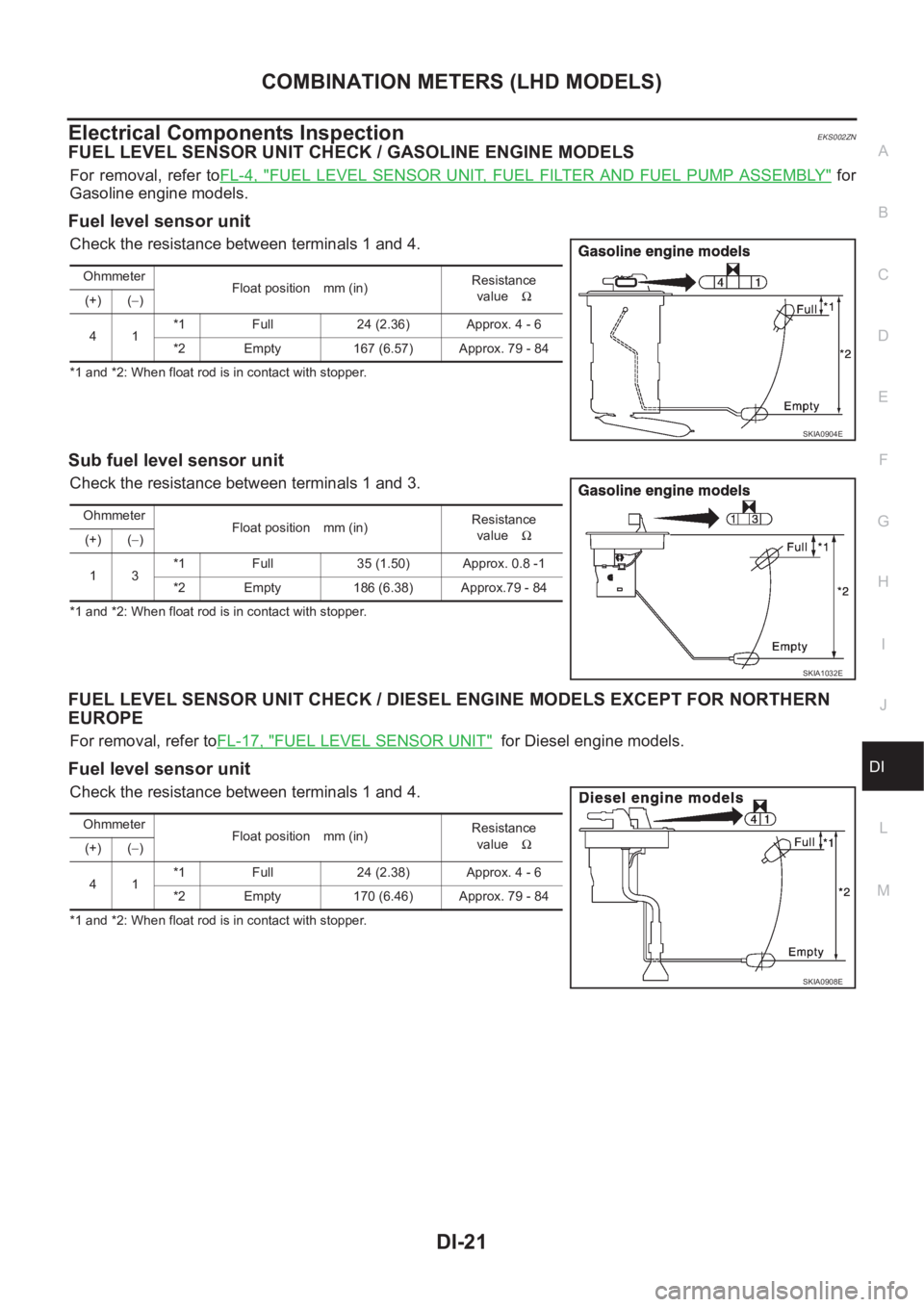
FUEL LEVEL SENSOR UNIT CHECK / GASOLINE ENGINE MODELS
For removal, refer toFL-4, "FUEL LEVEL SENSOR UNIT, FUEL FILTER AND FUEL PUMP ASSEMBLY" for
Gasoline engine models.
Fuel level sensor unit
Check the resistance between terminals 1 and 4.
*1 and *2: When float rod is in contact with stopper.
Sub fuel level sensor unit
Check the resistance between terminals 1 and 3.
*1 and *2: When float rod is in contact with stopper.
FUEL LEVEL SENSOR UNIT CHECK / DIESEL ENGINE MODELS EXCEPT FOR NORTHERN
EUROPE
For removal, refer toFL-17, "FUEL LEVEL SENSOR UNIT" for Diesel engine models.
Fuel level sensor unit
Check the resistance between terminals 1 and 4.
*1 and *2: When float rod is in contact with stopper.Ohmmeter
Float position mm (in)Resistance
valueΩ
(+) (−)
41*1 Full 24 (2.36) Approx. 4 - 6
*2 Empty 167 (6.57) Approx. 79 - 84
SKIA0904E
Ohmmeter
Float position mm (in)Resistance
valueΩ
(+) (−)
13*1 Full 35 (1.50) Approx. 0.8 -1
*2 Empty 186 (6.38) Approx.79 - 84
SKIA1032E
Ohmmeter
Float position mm (in)Resistance
valueΩ
(+) (−)
41*1 Full 24 (2.38) Approx. 4 - 6
*2 Empty 170 (6.46) Approx. 79 - 84
SKIA0908E
Page 3580 of 3833
DI-22
COMBINATION METERS (LHD MODELS)
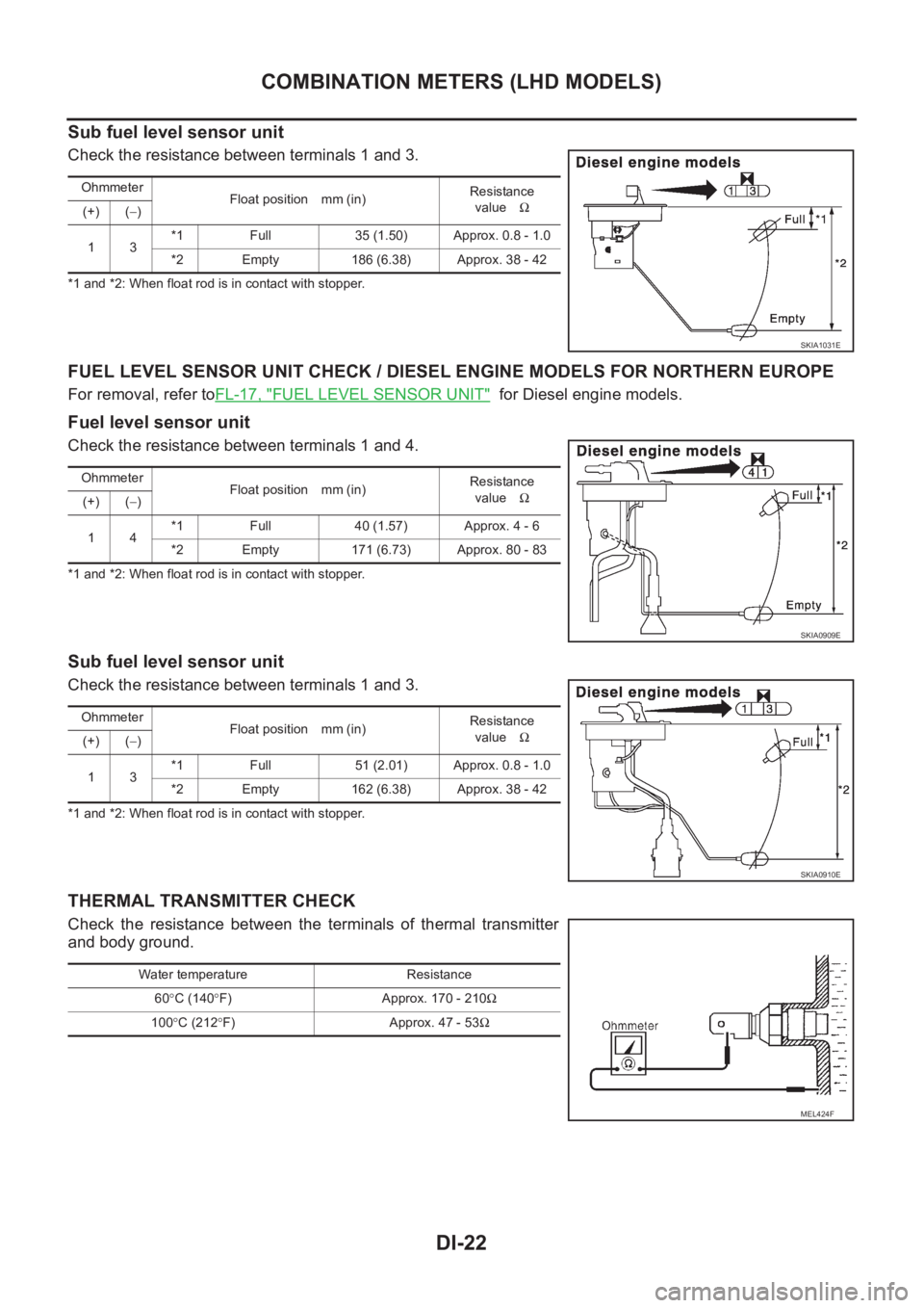
Sub fuel level sensor unit
Check the resistance between terminals 1 and 3.
*1 and *2: When float rod is in contact with stopper.
FUEL LEVEL SENSOR UNIT CHECK / DIESEL ENGINE MODELS FOR NORTHERN EUROPE
For removal, refer toFL-17, "FUEL LEVEL SENSOR UNIT" for Diesel engine models.
Fuel level sensor unit
Check the resistance between terminals 1 and 4.
*1 and *2: When float rod is in contact with stopper.
Sub fuel level sensor unit
Check the resistance between terminals 1 and 3.
*1 and *2: When float rod is in contact with stopper.
THERMAL TRANSMITTER CHECK
Check the resistance between the terminals of thermal transmitter
and body ground.
Ohmmeter
Float position mm (in)Resistance
valueΩ
(+) (−)
13*1 Full 35 (1.50) Approx. 0.8 - 1.0
*2 Empty 186 (6.38) Approx. 38 - 42
SKIA1031E
Ohmmeter
Float position mm (in)Resistance
valueΩ
(+) (−)
14*1 Full 40 (1.57) Approx. 4 - 6
*2 Empty 171 (6.73) Approx. 80 - 83
SKIA0909E
Ohmmeter
Float position mm (in)Resistance
valueΩ
(+) (−)
13*1 Full 51 (2.01) Approx. 0.8 - 1.0
*2 Empty 162 (6.38) Approx. 38 - 42
SKIA0910E
Water temperature Resistance
60°C (140°F) Approx. 170 - 210Ω
100°C (212°F) Approx. 47 - 53Ω
MEL424F
Page 3582 of 3833
DI-24
COMBINATION METERS (RHD MODELS)
COMBINATION METERS (RHD MODELS)
PFP:24810
System DescriptionEKS0030H
UNIFIED CONTROL METER
●Speedometer, odo/trip meter, tachometer, fuel gauge and water temperature gauge are controlled totally
by control unit built-in combination meter.
●Digital meter is adopted for odo/trip meter.*
*The record of the odo meter is kept even if the battery cable is disconnected. The record of the trip meter
is erased when the battery cable is disconnected.
●Odo/trip meter segment can be checked in diagnosis mode.
●Meter/gauge can be checked in diagnosis mode.
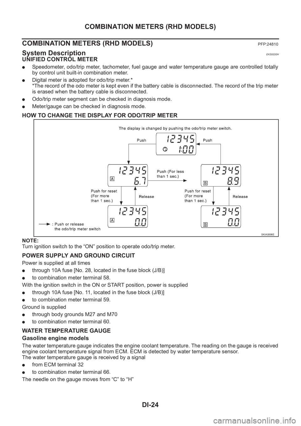
HOW TO CHANGE THE DISPLAY FOR ODO/TRIP METER
NOTE:
Turn ignition switch to the “ON” position to operate odo/trip meter.
POWER SUPPLY AND GROUND CIRCUIT
Power is supplied at all times
●through 10A fuse [No. 28, located in the fuse block (J/B)]
●to combination meter terminal 58.
With the ignition switch in the ON or START position, power is supplied
●through 10A fuse [No. 11, located in the fuse block (J/B)]
●to combination meter terminal 59.
Ground is supplied
●through body grounds M27 and M70
●to combination meter terminal 60.
WATER TEMPERATURE GAUGE
Gasoline engine models
The water temperature gauge indicates the engine coolant temperature. The reading on the gauge is received
engine coolant temperature signal from ECM. ECM is detected by water temperature sensor.
The water temperature gauge is received by a signal
●from ECM terminal 32
●to combination meter terminal 66.
The needle on the gauge moves from “C” to “H”
SKIA0896E
Page 3583 of 3833
COMBINATION METERS (RHD MODELS)
DI-25
C
D
E
F
G
H
I
J
L
MA
B
DI
Diesel engine models
The water temperature gauge indicates the engine coolant temperature. The reading on the gauge is based
on the resistance of the thermal transmitter.
As the temperature of the coolant increases, the resistance of the thermal transmitter decreases. A variable
ground is supplied to terminal 66 of the combination meter for the water temperature gauge. The needle on
the gauge moves from “C” to “H”.
TACHOMETER
The tachometer indicates engine speed in revolutions per minute (rpm).
The tachometer is regulated by a signal
●from terminal 36 (Gasoline engine models) or D1 (Diesel engine models) of the ECM
●to combination meter terminal 41 for the tachometer.
FUEL GAUGE
The fuel gauge indicates the approximate fuel level in the fuel tank.
The fuel gauge is regulated by a variable ground signal supplied
●from body grounds, B107 and B119
●through terminals 4 and 1 of the fuel level sensor unit and
●through terminals 1 and 3 of the sub fuel level sensor unit
●to combination meter terminal 40 for the fuel gauge.
SPEEDOMETER
The combination meter provides a voltage signal to the vehicle speed signal from 4WD/ABS control unit (with-
out ESP) or 4WD control unit (with ESP).
The voltage is supplied
●from combination meter terminal 42 for the speedometer
●to terminal 20 of 4WD control unit (with ESP) or 4WD/ABS control unit (without ESP).
The speedometer converts the voltage into the vehicle speed displayed.
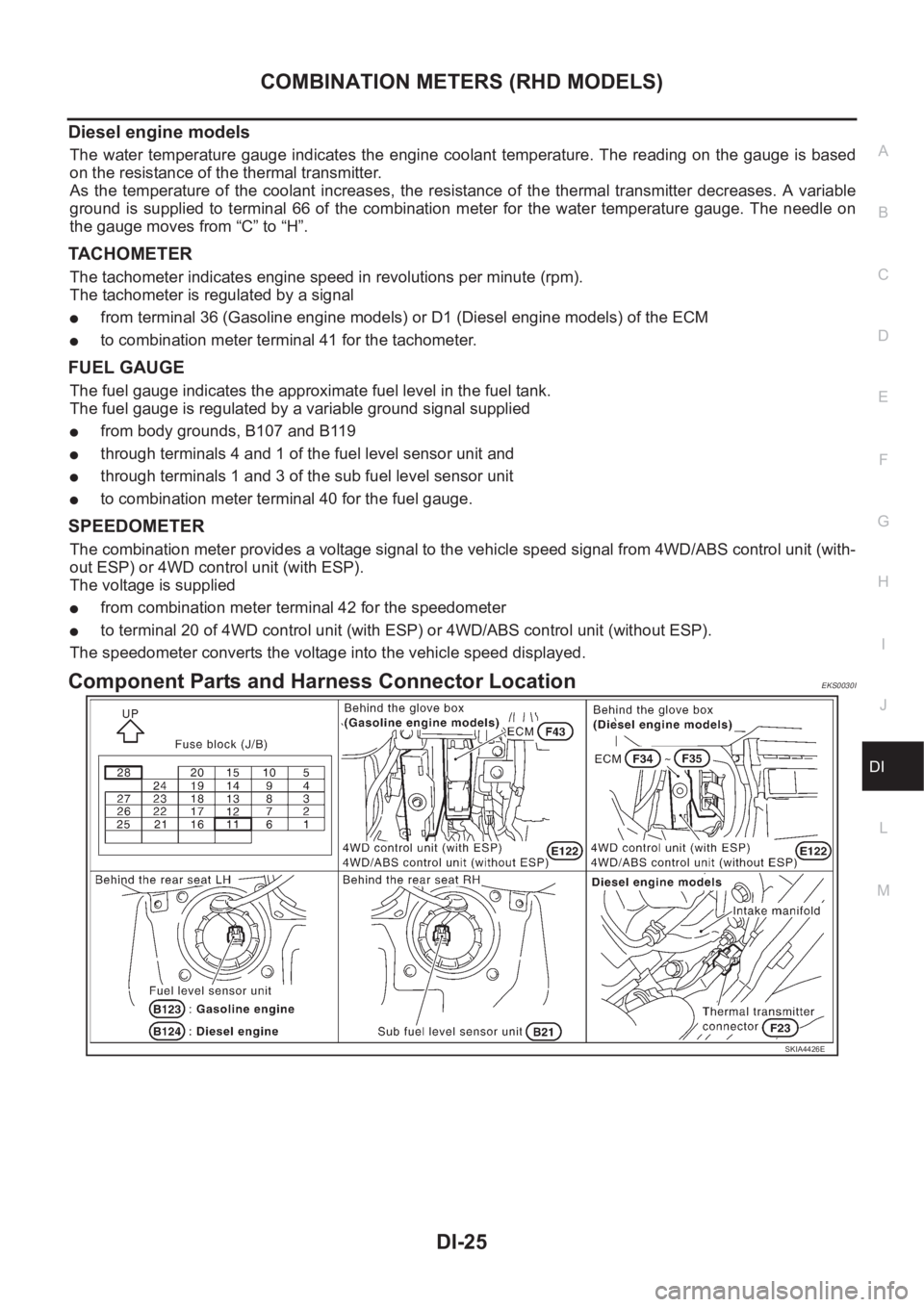
Component Parts and Harness Connector LocationEKS0030I
SKIA4426E