Page 500 of 1306

DIAGNOSTIC PROCEDURE
1 INSPECTION START
Start engine.
Is engine running?
Yes or No
YescGO TO 14.
NocGO TO 2.
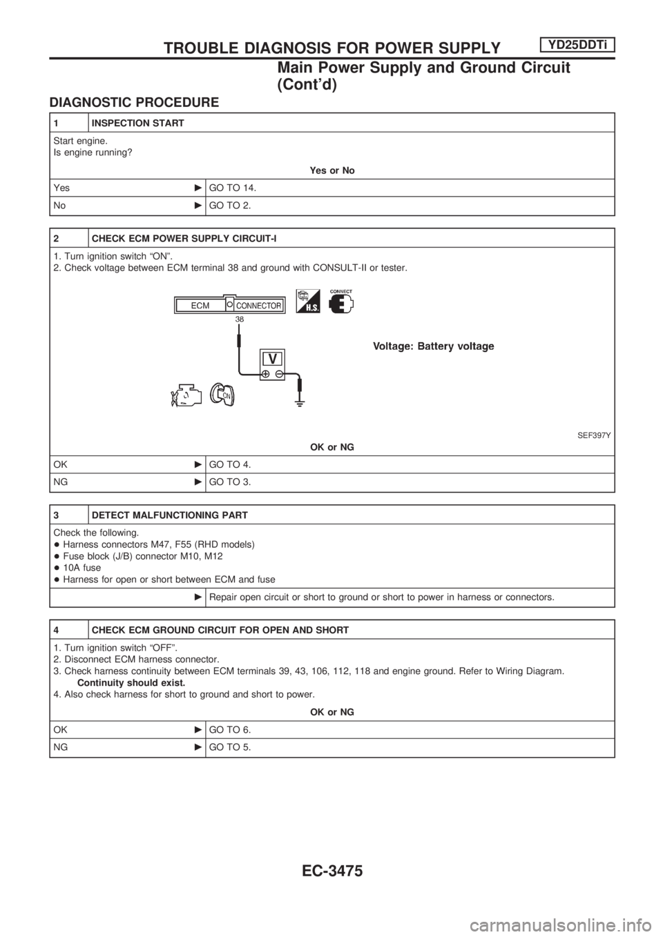
2 CHECK ECM POWER SUPPLY CIRCUIT-I
1. Turn ignition switch ªONº.
2. Check voltage between ECM terminal 38 and ground with CONSULT-II or tester.
SEF397Y
OK or NG
OKcGO TO 4.
NGcGO TO 3.
3 DETECT MALFUNCTIONING PART
Check the following.
+Harness connectors M47, F55 (RHD models)
+Fuse block (J/B) connector M10, M12
+10A fuse
+Harness for open or short between ECM and fuse
cRepair open circuit or short to ground or short to power in harness or connectors.
4 CHECK ECM GROUND CIRCUIT FOR OPEN AND SHORT
1. Turn ignition switch ªOFFº.
2. Disconnect ECM harness connector.
3. Check harness continuity between ECM terminals 39, 43, 106, 112, 118 and engine ground. Refer to Wiring Diagram.
Continuity should exist.
4. Also check harness for short to ground and short to power.
OK or NG
OKcGO TO 6.
NGcGO TO 5.
TROUBLE DIAGNOSIS FOR POWER SUPPLYYD25DDTi
Main Power Supply and Ground Circuit
(Cont'd)
EC-3475
Page 502 of 1306
7 CHECK ECM POWER SUPPLY CIRCUIT-III
1. Disconnect ECM relay.
SEC950C
2. Check voltage between relay terminals 2, 7 and ground with CONSULT-II or tester.
SEC241D
OK or NG
OKcGO TO 9.
NGcGO TO 8.
8 DETECT MALFUNCTIONING PART
Check the following.
+20A fuse
+Harness for open or short between ECM relay and fuse
cRepair open circuit or short to ground or short to power in harness or connectors.
9 CHECK OUTPUT SIGNAL CIRCUIT FOR OPEN AND SHORT
1. Disconnect ECM harness connector.
2. Check harness continuity between ECM terminal 4 and ECM relay terminal 1. Refer to Wiring Diagram.
Continuity should exist.
3. Also check harness for short to ground and short to power.
OK or NG
OKcGO TO 11.
NGcGO TO 10.
TROUBLE DIAGNOSIS FOR POWER SUPPLYYD25DDTi
Main Power Supply and Ground Circuit
(Cont'd)
EC-3477
Page 520 of 1306
4 CHECK COOLING FAN POWER SUPPLY CIRCUIT
1. Turn ignition switch ªOFFº.
2. Disconnect cooling fan relay.
SEC954C
3. Turn ignition switch ªONº.
4. Check voltage between cooling fan relay terminals 2, 5 and ground with CONSULT-II or tester.
SEC161D
OK or NG
OKcGO TO 6.
NGcGO TO 5.
5 DETECT MALFUNCTIONING PART
Check the following.
+Harness connectors M5, E101
+10A fuse
+30A fusible link
+Harness for open or short between cooling fan relay and fuse
+Harness for open or short between cooling fan relay and battery
cRepair open circuit or short to ground or short to power in harness or connectors.
DTC 0208 OVER HEATYD25DDTi
Diagnostic Procedure (Cont'd)
EC-3495
Page 566 of 1306
2 CHECK BATTERY AND ALTERNATOR
Check that the proper type of battery and alternator is installed.
Refer to EL section (ªBATTERYº and ªCHARGING SYSTEMº).
OK or NG
OKcGO TO 5.
NGcReplace with a proper one.
3 CHECK JUMPER CABLES INSTALLATION
Check that the jumper cables are connected in the correct sequence.
SEF488Z
OK or NG
OKcGO TO 4.
NGcReconnect jumper cables properly.
4 CHECK BATTERY FOR BOOSTER
Check that the battery for the booster is a 12V battery.
OK or NG
OKcGO TO 5.
NGcChange the vehicle for booster.
5 PERFORM DTC CONFIRMATION PROCEDURE AGAIN
Perform ªDTC Confirmation Procedureº, EC-3540, again.
OK or NG
OKcGO TO 6.
NGcReplace ECM.
6 CHECK ELECTRICAL PARTS DAMAGE
Check the following for damage.
+Wiring harness and harness connectors for burn
+Fuses for short
OK or NG
OKcINSPECTION END
NGcRepair or replace malfunctioning part.
DTC 0502 BATTERY VOLTAGEYD25DDTi
Diagnostic Procedure (Cont'd)
EC-3541
Page 614 of 1306
4 CHECK STOP LAMP SWITCH POWER SUPPLY CIRCUIT
1. Turn ignition switch ªOFFº.
2. Disconnect stop lamp switch harness connector.
SEC233D
3. Turn ignition switch ªONº.
4. Check voltage between stop lamp switch terminal 1 and ground with CONSULT-II or tester.
SEF435Y
OK or NG
OKcGO TO 6.
NGcGO TO 5.
5 DETECT MALFUNCTIONING PART
Check the following.
+10A fuse
+Harness for open or short between stop lamp switch and fuse
cRepair open circuit or short to ground or short to power in harness or connectors.
DTC 0807 ECM 14YD25DDTi
Diagnostic Procedure (Cont'd)
EC-3589
Page 621 of 1306
Diagnostic Procedure
1 CHECK ECM POWER SUPPLY CIRCUIT
1. Turn ignition switch ªOFFº.
2. Disconnect ECM relay.
SEC950C
3. Check voltage between ECM terminals 2, 7 and ground with CONSULT-II or tester.
SEC241D
OK or NG
OKcGO TO 3.
NGcGO TO 2.
2 DETECT MALFUNCTIONING PART
Check the following.
+20A fuse
+Harness for open and short between ECM relay and battery
cRepair open circuit or short to ground or short to power in harness or connectors.
3 CHECK ECM INPUT SIGNAL CIRCUIT FOR OPEN AND SHORT
1. Turn ignition switch ªOFFº.
2. Disconnect ECM harness connector.
3. Check harness continuity between ECM terminals 56, 61 and ECM relay terminal 6. Refer to Wiring Diagram.
Continuity should exist.
4. Also check harness for short to ground and short to power.
OK or NG
OKcGO TO 5.
NGcGO TO 4.
DTC 0902 ECM RLYYD25DDTi
EC-3596
Page 636 of 1306

5 DETECT MALFUNCTIONING PART
Check the following.
+10A fuse
+Harness for open or short between ECM relay and battery
cRepair open circuit or short to ground or short to power in harness or connectors.
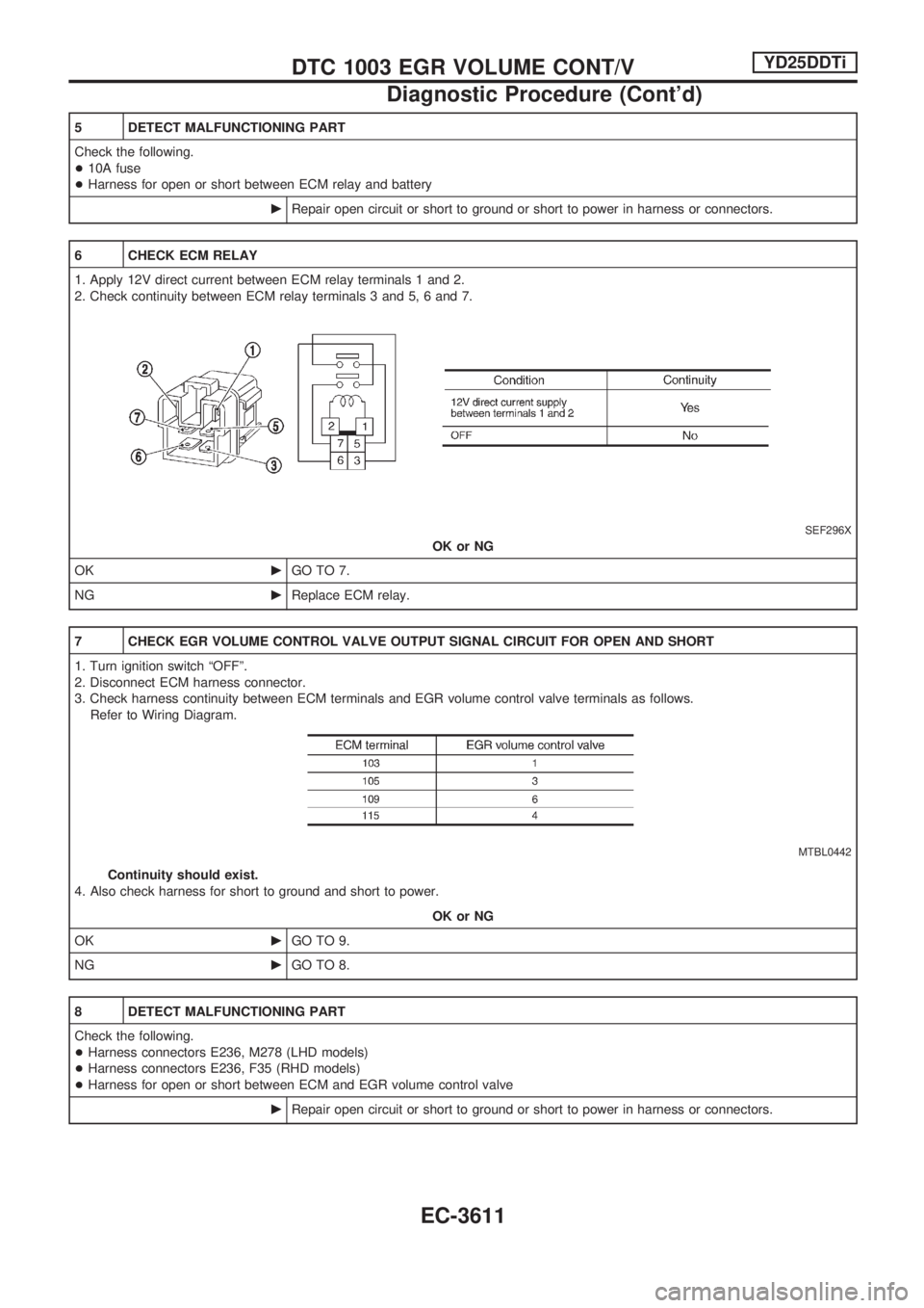
6 CHECK ECM RELAY
1. Apply 12V direct current between ECM relay terminals 1 and 2.
2. Check continuity between ECM relay terminals 3 and 5, 6 and 7.
SEF296X
OK or NG
OKcGO TO 7.
NGcReplace ECM relay.
7 CHECK EGR VOLUME CONTROL VALVE OUTPUT SIGNAL CIRCUIT FOR OPEN AND SHORT
1. Turn ignition switch ªOFFº.
2. Disconnect ECM harness connector.
3. Check harness continuity between ECM terminals and EGR volume control valve terminals as follows.
Refer to Wiring Diagram.
MTBL0442
Continuity should exist.
4. Also check harness for short to ground and short to power.
OK or NG
OKcGO TO 9.
NGcGO TO 8.
8 DETECT MALFUNCTIONING PART
Check the following.
+Harness connectors E236, M278 (LHD models)
+Harness connectors E236, F35 (RHD models)
+Harness for open or short between ECM and EGR volume control valve
cRepair open circuit or short to ground or short to power in harness or connectors.
DTC 1003 EGR VOLUME CONT/VYD25DDTi
Diagnostic Procedure (Cont'd)
EC-3611
Page 651 of 1306

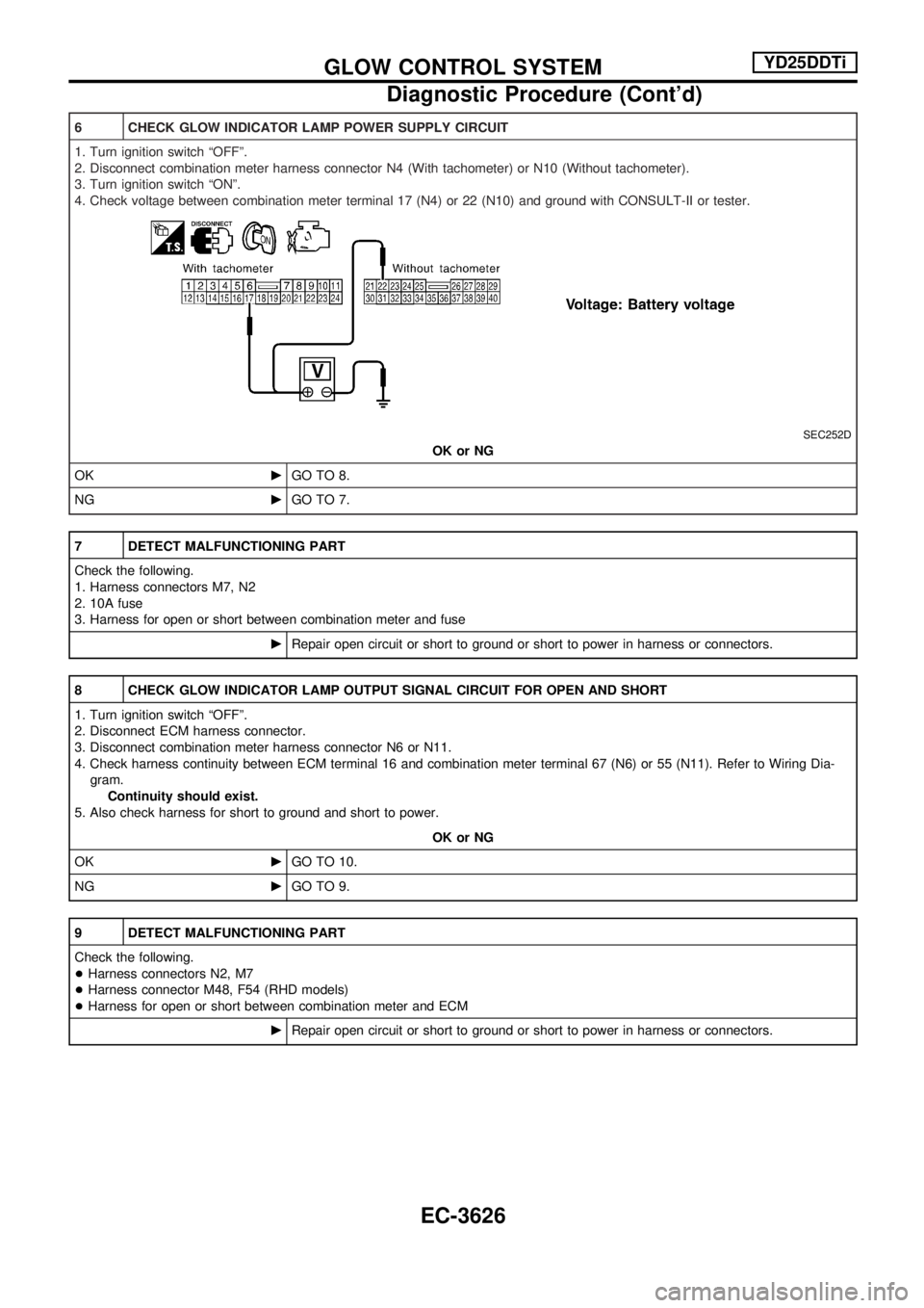
6 CHECK GLOW INDICATOR LAMP POWER SUPPLY CIRCUIT
1. Turn ignition switch ªOFFº.
2. Disconnect combination meter harness connector N4 (With tachometer) or N10 (Without tachometer).
3. Turn ignition switch ªONº.
4. Check voltage between combination meter terminal 17 (N4) or 22 (N10) and ground with CONSULT-II or tester.
SEC252D
OK or NG
OKcGO TO 8.
NGcGO TO 7.
7 DETECT MALFUNCTIONING PART
Check the following.
1. Harness connectors M7, N2
2. 10A fuse
3. Harness for open or short between combination meter and fuse
cRepair open circuit or short to ground or short to power in harness or connectors.
8 CHECK GLOW INDICATOR LAMP OUTPUT SIGNAL CIRCUIT FOR OPEN AND SHORT
1. Turn ignition switch ªOFFº.
2. Disconnect ECM harness connector.
3. Disconnect combination meter harness connector N6 or N11.
4. Check harness continuity between ECM terminal 16 and combination meter terminal 67 (N6) or 55 (N11). Refer to Wiring Dia-
gram.
Continuity should exist.
5. Also check harness for short to ground and short to power.
OK or NG
OKcGO TO 10.
NGcGO TO 9.
9 DETECT MALFUNCTIONING PART
Check the following.
+Harness connectors N2, M7
+Harness connector M48, F54 (RHD models)
+Harness for open or short between combination meter and ECM
cRepair open circuit or short to ground or short to power in harness or connectors.
GLOW CONTROL SYSTEMYD25DDTi
Diagnostic Procedure (Cont'd)
EC-3626