Page 657 of 1306
3 DETECT MALFUNCTIONING PART
Check the following.
+Harness connectors M48, F54 (RHD models)
+10A fuse
+Fuse block (J/B) connectors M10, M12
+Harness for open or short between ECM and ignition switch
cRepair open circuit or short to ground or short to power in harness or connectors.
4 CHECK INTERMITTENT INCIDENT
Refer to ªTROUBLE DIAGNOSIS FOR INTERMITTENT INCIDENTº, EC-3469.
cINSPECTION END
START SIGNALYD25DDTi
Diagnostic Procedure (Cont'd)
EC-3632
Page 666 of 1306

4 CHECK OVERALL FUNCTION-II
Check the indicator when turning ªONº and ªOFFº the heat up switch.
MTBL1314
OK or NG
OKcINSPECTION END
NGcGO TO 10.
5 CHECK HEAT UP SWITCH POWER SUPPLY CIRCUIT
1. Turn heat up switch ªOFFº.
2. Turn ignition switch ªOFFº.
3. Disconnect heat up switch harness connector.
4. Turn ignition switch ªONº.
5. Check voltage between heat up switch terminal 6 and ground with CONSULT-II or tester.
SEF304Z
OK or NG
OKcGO TO 7.
NGcGO TO 6.
6 DETECT MALFUNCTIONING PART
Check the following.
+Harness connectors N1, M6
+10A fuse
+Harness for open or short between heat up switch and fuse
cRepair open circuit or short to ground or short to power in harness or connectors.
7 CHECK HEAT UP SWITCH INPUT SIGNAL CIRCUIT FOR OPEN OR SHORT
1. Turn ignition switch ªOFFº.
2. Disconnect ECM harness connector.
3. Check harness continuity between ECM terminal 59 and heat up switch terminal 5. Refer to Wiring Diagram.
Continuity should exist.
4. Also check harness for short to ground and short to power.
OK or NG
OKcGO TO 9.
NGcGO TO 8.
HEAT UP SWITCHYD25DDTi
Diagnostic Procedure (Cont'd)
EC-3641
Page 724 of 1306

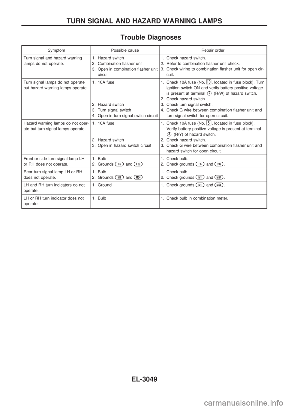
Trouble Diagnoses
Symptom Possible cause Repair order
Turn signal and hazard warning
lamps do not operate.1. Hazard switch
2. Combination flasher unit
3. Open in combination flasher unit
circuit1. Check hazard switch.
2. Refer to combination flasher unit check.
3. Check wiring to combination flasher unit for open cir-
cuit.
Turn signal lamps do not operate
but hazard warning lamps operate.1. 10A fuse
2. Hazard switch
3. Turn signal switch
4. Open in turn signal switch circuit1. Check 10A fuse (No.
10, located in fuse block). Turn
ignition switch ON and verify battery positive voltage
is present at terminal
V2(R/W) of hazard switch.
2. Check hazard switch.
3. Check turn signal switch.
4. Check G wire between combination flasher unit and
turn signal switch for open circuit.
Hazard warning lamps do not oper-
ate but turn signal lamps operate.1. 10A fuse
2. Hazard switch
3. Open in hazard switch circuit1. Check 10A fuse (No.
5, located in fuse block).
Verify battery positive voltage is present at terminal
V3(R/Y) of hazard switch.
2. Check hazard switch.
3. Check G wire between combination flasher unit and
hazard switch for open circuit.
Front or side turn signal lamp LH
or RH does not operate.1. Bulb
2. Grounds
E6andE39
1. Check bulb.
2. Check grounds
E6andE39.
Rear turn signal lamp LH or RH
does not operate.1. Bulb
2. Grounds
M1andM54
1. Check bulb.
2. Check grounds
M1andM54.
LH and RH turn indicators do not
operate.1. Ground 1. Check grounds
M1andM54.
LH or RH turn indicator does not
operate.1. Bulb 1. Check bulb in combination meter.
TURN SIGNAL AND HAZARD WARNING LAMPS
EL-3049
Page 747 of 1306
POWER SUPPLY AND GROUND CIRCUIT CHECK
Power supply circuit check
Terminals Ignition switch position
Å@OFF ACC ON
V18(R/G) GroundBattery
voltageBattery
voltageBattery
voltage
V17(W/B) Ground 0V 0VBattery
voltage
If NG, check the following.
+10A fuse [No.
11, located in fuse block (J/B)]
+10A fuse [No.
6, located in fuse block (J/B)]
+Harness for open or short between fuse and combination
meter
Ground circuit check
Terminals Continuity
V24- Ground (B) Yes
SEL404Y
SEL405Y
METER AND GAUGES
Trouble Diagnoses/With Tachometer (Cont'd)
EL-3072
Page 752 of 1306
POWER SUPPLY AND GROUND CIRCUIT CHECK
Power supply circuit check
Terminals Ignition switch position
Å@OFF ACC ON
V21(R/G) GroundBattery
voltageBattery
voltageBattery
voltage
V22(W/B) Ground 0V 0VBattery
voltage
If NG, check the following.
+10A fuse [No.
6, located in fuse block (J/B)]
+10A fuse [No.
11, located in fuse block (J/B)]
+Harness for open or short between fuse and combination
meter
Ground circuit check
Terminals Continuity
V23- Ground (B) Yes
SEL618Y
SEL619Y
METER AND GAUGES
Trouble Diagnoses/Without Tachometer
(Cont'd)
EL-3077
Page 805 of 1306

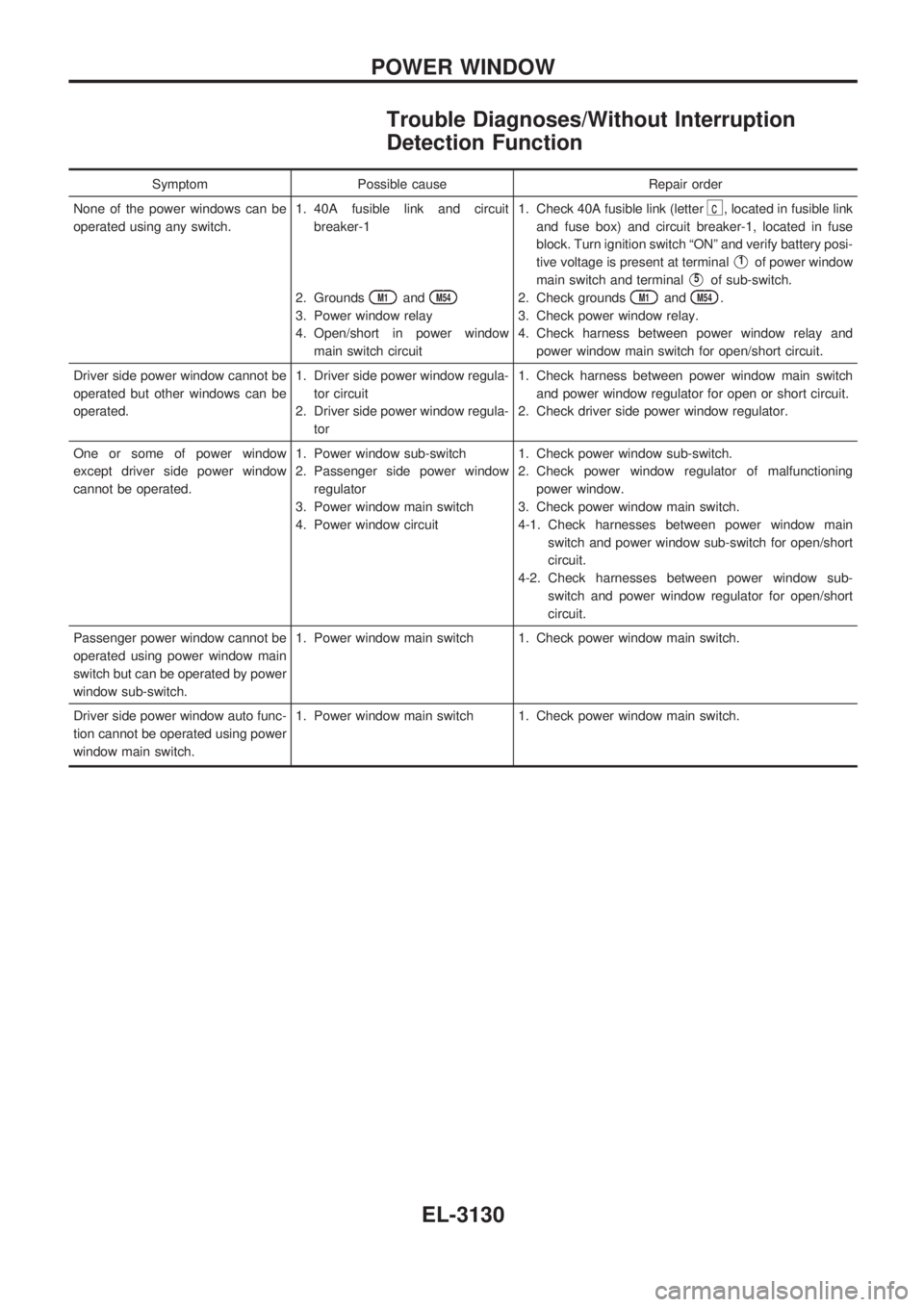
Trouble Diagnoses/Without Interruption
Detection Function
Symptom Possible cause Repair order
None of the power windows can be
operated using any switch.1. 40A fusible link and circuit
breaker-1
2. Grounds
M1andM54
3. Power window relay
4. Open/short in power window
main switch circuit1. Check 40A fusible link (letter
c, located in fusible link
and fuse box) and circuit breaker-1, located in fuse
block. Turn ignition switch ªONº and verify battery posi-
tive voltage is present at terminal
V1of power window
main switch and terminal
V5of sub-switch.
2. Check grounds
M1andM54.
3. Check power window relay.
4. Check harness between power window relay and
power window main switch for open/short circuit.
Driver side power window cannot be
operated but other windows can be
operated.1. Driver side power window regula-
tor circuit
2. Driver side power window regula-
tor1. Check harness between power window main switch
and power window regulator for open or short circuit.
2. Check driver side power window regulator.
One or some of power window
except driver side power window
cannot be operated.1. Power window sub-switch
2. Passenger side power window
regulator
3. Power window main switch
4. Power window circuit1. Check power window sub-switch.
2. Check power window regulator of malfunctioning
power window.
3. Check power window main switch.
4-1. Check harnesses between power window main
switch and power window sub-switch for open/short
circuit.
4-2. Check harnesses between power window sub-
switch and power window regulator for open/short
circuit.
Passenger power window cannot be
operated using power window main
switch but can be operated by power
window sub-switch.1. Power window main switch 1. Check power window main switch.
Driver side power window auto func-
tion cannot be operated using power
window main switch.1. Power window main switch 1. Check power window main switch.
POWER WINDOW
EL-3130
Page 806 of 1306

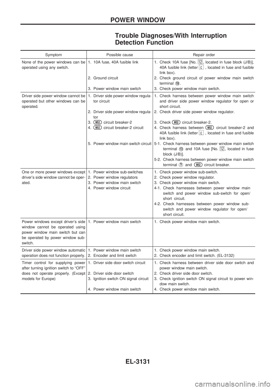
Trouble Diagnoses/With Interruption
Detection Function
Symptom Possible cause Repair order
None of the power windows can be
operated using any switch.1. 10A fuse, 40A fusible link
2. Ground circuit
3. Power window main switch1. Check 10A fuse [No.
12, located in fuse block (J/B)],
40A fusible link (letter
c, located in fuse and fusible
link box).
2. Check ground circuit of power window main switch
terminal
V19.
3. Check power window main switch.
Driver side power window cannot be
operated but other windows can be
operated.1. Driver side power window regula-
tor circuit
2. Driver side power window regula-
tor
3.
M52circuit breaker-2
4.
M52circuit breaker-2 circuit
5. Power window main switch circuit1. Check harness between power window main switch
and driver side power window regulator for open or
short circuit.
2. Check driver side power window regulator.
3. Check
M52circuit breaker-2.
4. Check harness between
M52circuit breaker-2 and
40A fusible link (letter
c, located in fuse and fusible
link box).
5-1. Check harness between power window main switch
terminal
V13and 10A fuse [No.12, located in fuse
block (J/B)].
5-2. Check harness between power window main switch
terminal
V5andM52circuit breaker.
One or more power windows except
driver's side window cannot be oper-
ated.1. Power window sub-switches
2. Power window regulators
3. Power window main switch
4. Power window circuit1. Check power window sub-switch.
2. Check power window regulator.
3. Check power window main switch.
4-1. Check harnesses between power window main
switch and power window sub-switch for open/
short circuit.
4-2. Check harnesses between power window sub-
switch and power window regulator for open/
short circuit.
Power windows except driver's side
window cannot be operated using
power window main switch but can
be operated by power window sub-
switch.1. Power window main switch 1. Check power window main switch.
Driver side power window automatic
operation does not function properly.1. Power window main switch
2. Encoder and limit switch1. Check power window main switch.
2. Check encoder and limit switch. (EL-3132)
Timer control for supplying power
after turning ignition switch to ªOFFº
does not operate properly. (Except
models for Europe)1. Driver side door switch circuit
2. Driver side door switch
3. Ignition switch ON signal circuit
4. Power window main switch1. Check harness between driver side door switch and
power window main switch.
2. Check driver side door switch.
3. Check ignition switch ON signal circuit to power win-
dow main switch.
4. Check power window main switch.
POWER WINDOW
EL-3131
Page 822 of 1306
CONSULT-II
CONSULT-II INSPECTION PROCEDURE
1. Turn ignition switch OFF.
2. Insert NATS program card into CONSULT-II.
Program card
AEN00A/B
3. Connect CONSULT-II to Data link connector which is located
behind the fuse box cover.
4. Turn ignition switch ON.
5. Touch ªSTARTº.
6. Perform each diagnostic test mode according to each service
procedure.
For further information, see the CONSULT-II Operation
Manual, NATS.
SEL595Y
SEL617Y
SEL150X
NATS (Nissan Anti-Theft System)
EL-3147