2001 NISSAN ALMERA TINO air condition
[x] Cancel search: air conditionPage 2171 of 3051
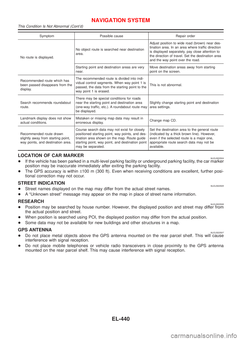
Symptom Possible cause Repair order
No route is displayed.No object route is searched near destination
area.Adjust position to wide road (brown) near des-
tination area. In an area where traffic direction
is displayed separately, pay close attention to
the direction of travel. Set the destination area
and the way point over the road.
Starting point and destination areas are very
near.Move destination areas away from starting
point on the screen.
Recommended route which has
been passed disappears from the
display.The recommended route is divided into indi-
vidual control segments. When way point 1 is
passed, the data from the starting point to the
way point 1 is erased.This is not abnormal.
Search recommends roundabout
route.There may be special conditions for roads
near the starting point and destination area
(one-way traffic, etc.). A roundabout route may
be displayed.Slightly change starting point and destination
area settings.
Landmark display does not show
actual conditions.Mistaken or missing map data may result in
erroneous display.Change map CD.
Recommended route drawn
slightly away from starting point,
way points, and destination area.Course search data may not exist for closely
positioned starting point, way points, and des-
tination area shown on the map. Route guide
starting point, way point, and destination point
may be separated.Set the destination area to the general route
(indicated by a thick brown line). However,
even if the selected route is a major one,
appropriate route search data may not be
available.
LOCATION OF CAR MARKERNLEL0522S04+If the vehicle has been parked in a multi-level parking facility or underground parking facility, the car marker
position may be inaccurate immediately after exiting the parking facility.
+The GPS accuracy is within±100 m (300 ft). Even when receiving conditions are excellent, further posi-
tional correction may not occur.
STREET INDICATIONNLEL0522S05+Street names displayed on the map may differ from the actual street names.
+A ªUnknown streetº message may appear on the map in place of street name information.
RESEARCHNLEL0522S06+Position may be searched by house number. However, the displayed position and street may differ from
the actual position and street.
+When position is searched using POI, the displayed position may differ from the actual position.
+Some data may not be available for new buildings and other structures in a map.
GPS ANTENNANLEL0522S07+Do not place metal objects above the GPS antenna mounted on the rear parcel shelf. This will cause
interference with signal reception.
+Do not place mobile telephones or vehicle radio transceivers in close proximity to the GPS antenna
mounted on the rear parcel shelf. This may cause interference with signal reception.
NAVIGATION SYSTEM
This Condition Is Not Abnormal (Cont'd)
EL-440
Page 2256 of 3051
NLEL0311
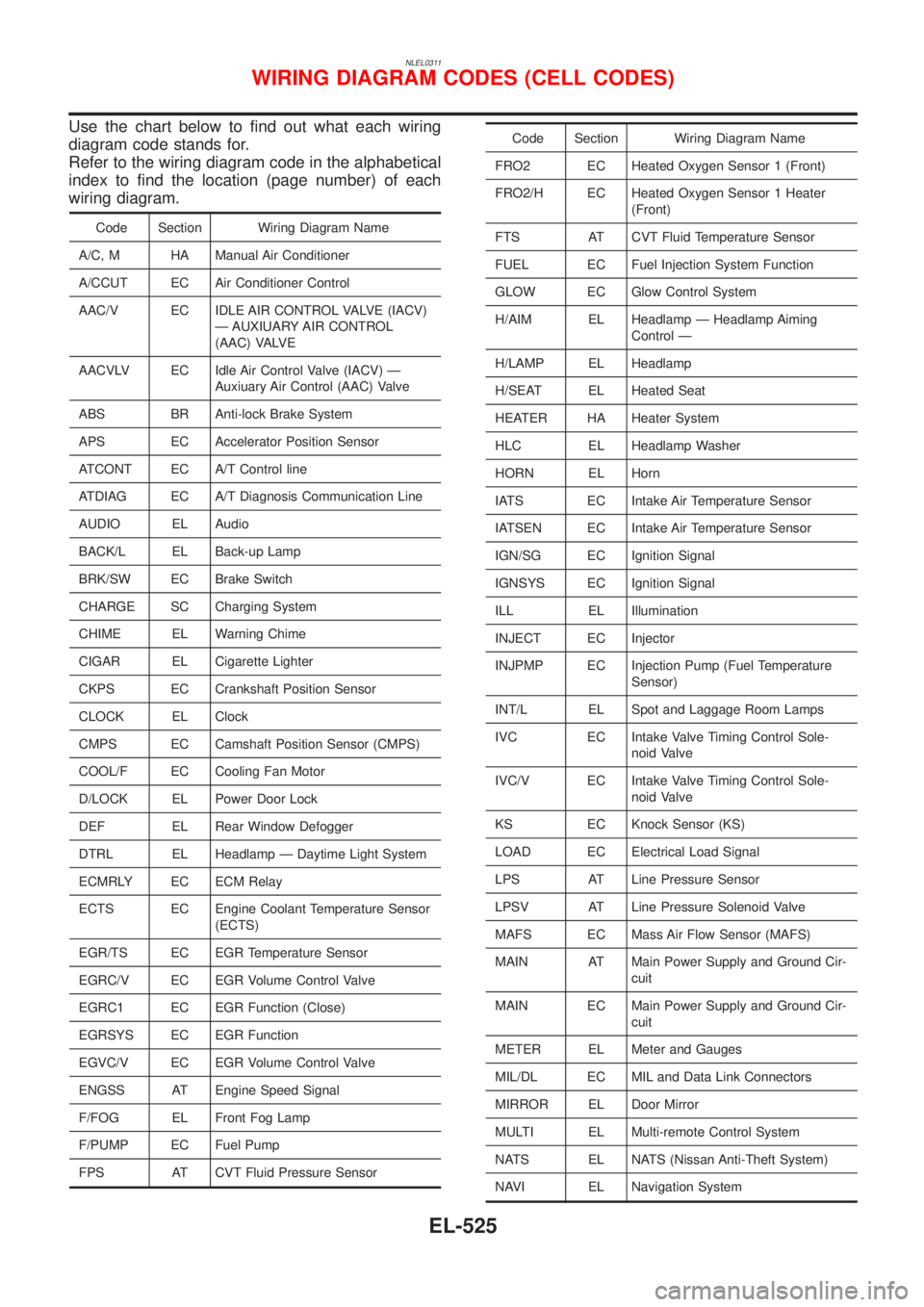
Use the chart below to find out what each wiring
diagram code stands for.
Refer to the wiring diagram code in the alphabetical
index to find the location (page number) of each
wiring diagram.
Code Section Wiring Diagram Name
A/C, M HA Manual Air Conditioner
A/CCUT EC Air Conditioner Control
AAC/V EC IDLE AIR CONTROL VALVE (IACV)
Ð AUXIUARY AIR CONTROL
(AAC) VALVE
AACVLV EC Idle Air Control Valve (IACV) Ð
Auxiuary Air Control (AAC) Valve
ABS BR Anti-lock Brake System
APS EC Accelerator Position Sensor
ATCONT EC A/T Control line
ATDIAG EC A/T Diagnosis Communication Line
AUDIO EL Audio
BACK/L EL Back-up Lamp
BRK/SW EC Brake Switch
CHARGE SC Charging System
CHIME EL Warning Chime
CIGAR EL Cigarette Lighter
CKPS EC Crankshaft Position Sensor
CLOCK EL Clock
CMPS EC Camshaft Position Sensor (CMPS)
COOL/F EC Cooling Fan Motor
D/LOCK EL Power Door Lock
DEF EL Rear Window Defogger
DTRL EL Headlamp Ð Daytime Light System
ECMRLY EC ECM Relay
ECTS EC Engine Coolant Temperature Sensor
(ECTS)
EGR/TS EC EGR Temperature Sensor
EGRC/V EC EGR Volume Control Valve
EGRC1 EC EGR Function (Close)
EGRSYS EC EGR Function
EGVC/V EC EGR Volume Control Valve
ENGSS AT Engine Speed Signal
F/FOG EL Front Fog Lamp
F/PUMP EC Fuel Pump
FPS AT CVT Fluid Pressure Sensor
Code Section Wiring Diagram Name
FRO2 EC Heated Oxygen Sensor 1 (Front)
FRO2/H EC Heated Oxygen Sensor 1 Heater
(Front)
FTS AT CVT Fluid Temperature Sensor
FUEL EC Fuel Injection System Function
GLOW EC Glow Control System
H/AIM EL Headlamp Ð Headlamp Aiming
Control Ð
H/LAMP EL Headlamp
H/SEAT EL Heated Seat
HEATER HA Heater System
HLC EL Headlamp Washer
HORN EL Horn
IATS EC Intake Air Temperature Sensor
IATSEN EC Intake Air Temperature Sensor
IGN/SG EC Ignition Signal
IGNSYS EC Ignition Signal
ILL EL Illumination
INJECT EC Injector
INJPMP EC Injection Pump (Fuel Temperature
Sensor)
INT/L EL Spot and Laggage Room Lamps
IVC EC Intake Valve Timing Control Sole-
noid Valve
IVC/V EC Intake Valve Timing Control Sole-
noid Valve
KS EC Knock Sensor (KS)
LOAD EC Electrical Load Signal
LPS AT Line Pressure Sensor
LPSV AT Line Pressure Solenoid Valve
MAFS EC Mass Air Flow Sensor (MAFS)
MAIN AT Main Power Supply and Ground Cir-
cuit
MAIN EC Main Power Supply and Ground Cir-
cuit
METER EL Meter and Gauges
MIL/DL EC MIL and Data Link Connectors
MIRROR EL Door Mirror
MULTI EL Multi-remote Control System
NATS EL NATS (Nissan Anti-Theft System)
NAVI EL Navigation System
WIRING DIAGRAM CODES (CELL CODES)
EL-525
Page 2260 of 3051
PISTON RING END GAP........................................135
CONNECTING ROD BEND AND TORSION.............136
CYLINDER BLOCK DISTORTION AND WEAR.........136
PISTON-TO-BORE CLEARANCE............................137
CRANKSHAFT.......................................................138
BEARING CLEARANCE.........................................138
CONNECTING ROD BUSHING CLEARANCE
(SMALL END)
........................................................141
REPLACEMENT OF CONNECTING ROD
BUSHING (SMALL END)
........................................141
REPLACEMENT OF PILOT CONVERTER (CVT).....141
DRIVE PLATE RUNOUT........................................142
Assembly .................................................................142
PISTON................................................................142
CRANKSHAFT.......................................................143
SERVICE DATA AND SPECIFICATIONS (SDS).......146
General Specifications .............................................146
Compression Pressure ............................................146
Cylinder Head ..........................................................146
Valve ........................................................................147
VALVE..................................................................147
VALVE SPRING.....................................................147
HYDRAULIC LASH ADJUSTER (HLA).....................147
VALVE GUIDE.......................................................148
VALVE SHIM CLEARANCE ADJUSTMENT..............148
AVAILABLE SHIM..................................................149
VALVE SEAT.........................................................150
Camshaft and Camshaft Bearing ............................151
Cylinder Block ..........................................................152
Piston, Piston Ring and Piston Pin .........................153
PISTON................................................................153
PISTON RING.......................................................153
PISTON PIN..........................................................153
Connecting Rod .......................................................154
Crankshaft................................................................155
Main Bearing............................................................156
STANDARD...........................................................156
UNDERSIZE..........................................................156
Connecting Rod Bearing .........................................156
STANDARD SIZE..................................................156
UNDERSIZE..........................................................156
Bearing Clearance ...................................................157
Miscellaneous Components.....................................157
YD
PRECAUTIONS...........................................................158
Parts Requiring Angular Tightening .........................158
Liquid Gasket Application Procedure ......................158
PREPARATION...........................................................159
Special Service Tools ..............................................159
Commercial Service Tools .......................................161
NOISE, VIBRATION AND HARSHNESS (NVH)
TROUBLESHOOTING.................................................163
NVH Troubleshooting - Engine Noise .....................163MEASUREMENT OF COMPRESSION PRESSURE..164
DRIVE BELTS..............................................................166
Inspection.................................................................166
Adjustment ...............................................................166
AIR CONDITIONER COMPRESSOR BELT..............167
ALTERNATOR & WATER PUMP BELT...................167
Removal ...................................................................167
Installation ................................................................168
AIR CLEANER.............................................................169
Changing Air Cleaner Filter .....................................169
VISCOUS PAPER TYPE.........................................169
OIL PAN.......................................................................170
Components.............................................................170
Removal ...................................................................170
Installation ................................................................172
TIMING CHAIN............................................................175
Secondary Timing Chain .........................................175
REMOVAL.............................................................175
INSPECTION.........................................................177
INSTALLATION......................................................177
Primary Timing Chain ..............................................180
REMOVAL.............................................................181
INSPECTION.........................................................183
INSTALLATION......................................................183
INTAKE MANIFOLD....................................................188
Removal and Installation .........................................188
PREPARATIVE WORK...........................................188
FUEL PIPING........................................................189
INTAKE MANIFOLD...............................................189
EGR VOLUME CONTROL VALVE...........................189
WATER HOSE.......................................................189
Inspection.................................................................190
INTAKE MANIFOLD...............................................190
SWIRL CONTROL VALVE......................................190
CATALYST..................................................................191
Removal and Installation .........................................191
PREPARATIVE WORK...........................................191
THREE WAY CATALYST.......................................191
GUSSET...............................................................192
EXHAUST MANIFOLD, TURBOCHARGER...............193
Removal and Installation .........................................193
PREPARATIVE WORK...........................................193
EXHAUST MANIFOLD AND TURBOCHARGER.......193
EXHAUST MANIFOLD GASKET.............................194
Disassembly and Assembly .....................................194
TURBOCHARGER.................................................194
Inspection.................................................................195
EXHAUST MANIFOLD...........................................195
TURBOCHARGER.................................................195
ROCKER COVER........................................................198
Removal and Installation .........................................198
PREPARATIVE WORK...........................................198
ROCKER COVER..................................................198
CYLINDER HEAD........................................................200
CONTENTS(Cont'd)
EM-3
Page 2267 of 3051
NLEM0005
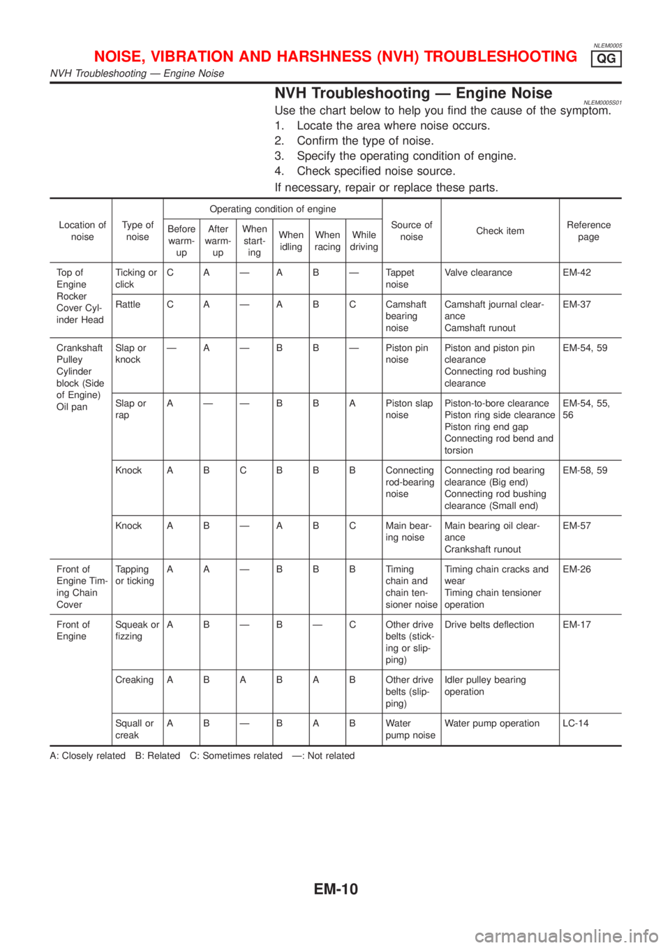
NVH Troubleshooting Ð Engine NoiseNLEM0005S01Use the chart below to help you find the cause of the symptom.
1. Locate the area where noise occurs.
2. Confirm the type of noise.
3. Specify the operating condition of engine.
4. Check specified noise source.
If necessary, repair or replace these parts.
Location of
noiseType of
noiseOperating condition of engine
Source of
noiseCheck itemReference
page Before
warm-
upAfter
warm-
upWhen
start-
ingWhen
idlingWhen
racingWhile
driving
To p o f
Engine
Rocker
Cover Cyl-
inder HeadTicking or
clickC A Ð A B Ð Tappet
noiseValve clearance EM-42
Rattle C A Ð A B C Camshaft
bearing
noiseCamshaft journal clear-
ance
Camshaft runoutEM-37
Crankshaft
Pulley
Cylinder
block (Side
of Engine)
Oil panSlap or
knockÐ A Ð B B Ð Piston pin
noisePiston and piston pin
clearance
Connecting rod bushing
clearanceEM-54, 59
Slap or
rapA Ð Ð B B A Piston slap
noisePiston-to-bore clearance
Piston ring side clearance
Piston ring end gap
Connecting rod bend and
torsionEM-54, 55,
56
Knock A B CB B B Connecting
rod-bearing
noiseConnecting rod bearing
clearance (Big end)
Connecting rod bushing
clearance (Small end)EM-58, 59
Knock A B Ð A B C Main bear-
ing noiseMain bearing oil clear-
ance
Crankshaft runoutEM-57
Front of
Engine Tim-
ing Chain
CoverTapping
or tickingAAÐBBBTiming
chain and
chain ten-
sioner noiseTiming chain cracks and
wear
Timing chain tensioner
operationEM-26
Front of
EngineSqueak or
fizzingA B Ð B Ð C Other drive
belts (stick-
ing or slip-
ping)Drive belts deflection EM-17
CreakingABABABOther drive
belts (slip-
ping)Idler pulley bearing
operation
Squall or
creakABÐBABWater
pump noiseWater pump operation LC-14
A: Closely related B: Related C: Sometimes related Ð: Not related
NOISE, VIBRATION AND HARSHNESS (NVH) TROUBLESHOOTINGQG
NVH Troubleshooting Ð Engine Noise
EM-10
Page 2297 of 3051
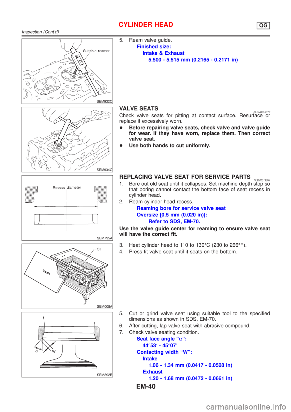
SEM932C
5. Ream valve guide.
Finished size:
Intake & Exhaust
5.500 - 5.515 mm (0.2165 - 0.2171 in)
SEM934C
VALVE SEATSNLEM0019S10Check valve seats for pitting at contact surface. Resurface or
replace if excessively worn.
+Before repairing valve seats, check valve and valve guide
for wear. If they have worn, replace them. Then correct
valve seat.
+Use both hands to cut uniformly.
SEM795A
REPLACING VALVE SEAT FOR SERVICE PARTSNLEM0019S111. Bore out old seat until it collapses. Set machine depth stop so
that boring cannot contact the bottom face of seat recess in
cylinder head.
2. Ream cylinder head recess.
Reaming bore for service valve seat
Oversize [0.5 mm (0.020 in)]:
Refer to SDS, EM-70.
Use the valve guide center for reaming to ensure valve seat
will have the correct fit.
SEM008A
3. Heat cylinder head to 110 to 130ÉC (230 to 266ÉF).
4. Press fit valve seat until it seats on the bottom.
SEM892B
5. Cut or grind valve seat using suitable tool to the specified
dimensions as shown in SDS, EM-70.
6. After cutting, lap valve seat with abrasive compound.
7. Check valve seating condition.
Seat face angle ªaº:
44É53¢- 45É07¢
Contacting width ªWº:
Intake
1.06 - 1.34 mm (0.0417 - 0.0528 in)
Exhaust
1.20 - 1.68 mm (0.0472 - 0.0661 in)
CYLINDER HEADQG
Inspection (Cont'd)
EM-40
Page 2307 of 3051
WARNING:
+Position vehicle on a flat and solid surface.
+Place chocks at front and back of rear wheels.
+Do not remove engine until exhaust system has com-
pletely cooled off, otherwise, you may burn yourself
and/or fire may break out in fuel line.
+Before disconnecting fuel hose, release pressure.
Refer to EC-43, ªFuel Pressure Releaseº.
+Be sure to lift engine and transaxle in a safe manner.
+For engines not equipped with engine slingers, attach
proper slingers and bolts described in PARTS CATALOG.
CAUTION:
+When lifting engine, be sure to clear surrounding parts.
Use special care near accelerator wire casing, brake lines
and brake master cylinder.
+When lifting the engine, always use engine slingers in a
safe manner.
+When removing drive shaft, be careful not to damage
grease seal of transaxle.
+Before separating engine and transaxle, remove crank-
shaft position sensor (POS) from the cylinder block
assembly.
+Always be extra careful not to damage edge of crankshaft
position sensor (POS), or signal plate teeth.
Engine cannot be removed separately from transaxle. Remove
engine with transaxle as an assembly.
REMOVALNLEM0022S011. Drain coolant from radiator and cylinder block. Refer to LC-18,
ªChanging Engine Coolantº.
2. Remove coolant reservoir tank and bracket.
3. Drain engine oil.
4. Remove battery and battery tray.
5. Remove air cleaner and air duct.
6. Remove drive belts.
7. Remove alternator and air conditioner compressor from
engine.
8. Remove power steering oil pump from engine and position
aside.
Power steering oil pump does not need to be disconnected
from power steering tubes.
ENGINE ASSEMBLYQG
Removal and Installation (Cont'd)
EM-50
Page 2321 of 3051
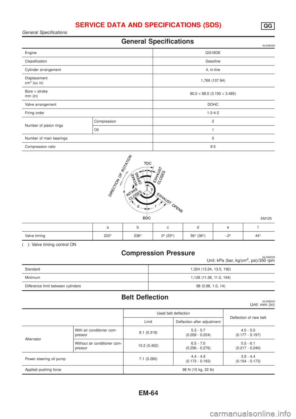
General SpecificationsNLEM0028
EngineQG18DE
ClassificationGasoline
Cylinder arrangement4, in-line
Displacement
cm
3(cu in)1,769 (107.94)
Bore´stroke
mm (in)80.0´88.0 (3.150´3.465)
Valve arrangementDOHC
Firing order1-3-4-2
Number of piston ringsCompression 2
Oil 1
Number of main bearings5
Compression ratio9.5
EM120
abcde f
Valve timing 222É 236É 0É (20É) 56É (36É) þ2É 44É
( ): Valve timing control ON
Compression PressureNLEM0029Unit: kPa (bar, kg/cm2, psi)/350 rpm
Standard1,324 (13.24, 13.5, 192)
Minimum1,128 (11.28, 11.5, 164)
Difference limit between cylinders 98 (0.98, 1.0, 14)
Belt DeflectionNLEM0045Unit: mm (in)
Used belt deflection
Deflection of new belt
Limit Deflection after adjustment
AlternatorWith air conditioner com-
pressor8.1 (0.319)5.3 - 5.7
(0.209 - 0.224)4.5 - 5.0
(0.177 - 0.197)
Without air conditioner com-
pressor10.2 (0.402)6.5 - 7.0
(0.256 - 0.276)5.5 - 6.1
(0.217 - 0.240)
Power steering oil pump 7.1 (0.280)4.4 - 4.9
(0.173 - 0.193)3.9 - 4.4
(0.154 - 0.173)
Applied pushing force98 N (10 kg, 22 lb)
SERVICE DATA AND SPECIFICATIONS (SDS)QG
General Specifications
EM-64
Page 2338 of 3051
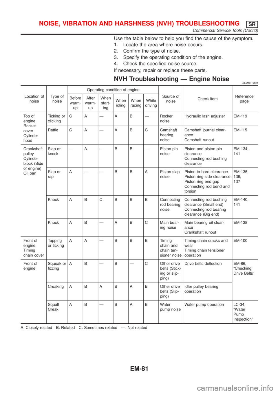
Use the table below to help you find the cause of the symptom.
1. Locate the area where noise occurs.
2. Confirm the type of noise.
3. Specify the operating condition of the engine.
4. Check the specified noise source.
If necessary, repair or replace these parts.
NVH Troubleshooting Ð Engine NoiseNLEM0116S01
Location of
noiseType of
noiseOperating condition of engine
Source of
noiseCheck itemReference
page Before
warm-
upAfter
warm-
upWhen
start-
ingWhen
idlingWhen
racingWhile
driving
To p o f
engine
Rocket
cover
Cylinder
headTicking or
clickingC A Ð A B Ð Rocker
noiseHydraulic lash adjuster EM-119
Rattle C A Ð A B C Camshaft
bearing
noiseCamshaft journal clear-
ance
Camshaft runoutEM-115
Crankshaft
pulley
Cylinder
block (Side
of engine)
Oil panSlap or
knockÐ A Ð B B Ð Piston pin
noisePiston and piston pin
clearance
Connecting rod bushing
clearanceEM-134,
141
Slap or
rapA Ð Ð B B A Piston slap
noisePiston-to-bore clearance
Piston ring side clearance
Piston ring end gap
Connecting rod bend and
torsionEM-135,
136,
137
Knock A B CB B B Connecting
rod bearing
noiseConnecting rod bushing
clearance (Small end)
Connecting rod bearing
clearance (Big end)EM-140,
141
Knock A B Ð A B C Main bear-
ing noiseMain bearing oil clear-
ance
Crankshaft runoutEM-138
Front of
engine
Timing
chain coverTapping
or tickingAAÐBBBTiming
chain and
chain ten-
sioner noiseTiming chain cracks and
wear
Timing chain tensioner
operationEM-100
Front of
engineSqueak or
fizzingA B Ð B Ð C Other drive
belts (Stick-
ing or slip-
ping)Drive belts deflection EM-86,
ªChecking
Drive Beltsº
CreakingABABABOther drive
belts (Slip-
ping)Idler pulley bearing
operation
Squall
CreakABÐBABWater
pump noiseWater pump operation LC-34,
ªWater
Pump
Inspectionº
A: Closely related B: Related C: Sometimes related Ð: Not related
NOISE, VIBRATION AND HARSHNESS (NVH) TROUBLESHOOTINGSR
Commercial Service Tools (Cont'd)
EM-81