2001 NISSAN ALMERA TINO air condition
[x] Cancel search: air conditionPage 1727 of 3051
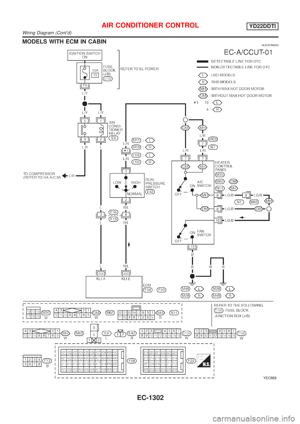
MODELS WITH ECM IN CABINNLEC0786S02
YEC869
AIR CONDITIONER CONTROLYD22DDTI
Wiring Diagram (Cont'd)
EC-1302
Page 1733 of 3051
Electrical Components Inspection ...........................164
WARNING CHIME.......................................................165
Component Parts and Harness Connector
Location ...................................................................165
System Description ..................................................165
Wiring Diagram - CHIME - ......................................166
Trouble Diagnoses...................................................170
FRONT WIPER AND WASHER..................................176
System Description ..................................................176
Wiring Diagram - WIPER - ......................................178
Removal and Installation .........................................182
Washer Nozzle Adjustment .....................................183
Washer Tube Layout ...............................................183
REAR WIPER AND WASHER....................................184
Wiring Diagram - WIP/R -........................................184
Removal and Installation .........................................188
Washer Nozzle Adjustment .....................................188
Washer Tube Layout ...............................................189
HEADLAMP WASHER................................................190
Wiring Diagram - HLC - ...........................................190
Washer Tube Layout ...............................................192
HORN...........................................................................193
Wiring Diagram - HORN - .......................................193
CIGARETTE LIGHTER................................................195
Wiring Diagram - CIGAR -.......................................195
CLOCK.........................................................................196
Wiring Diagram - CLOCK -......................................196
REAR WINDOW DEFOGGER.....................................198
System Description ..................................................198
Wiring Diagram - DEF - ...........................................199
Trouble Diagnoses...................................................203
Electrical Components Inspection ...........................205
Filament Check ........................................................206
Filament Repair .......................................................207
AUDIO..........................................................................208
System Description ..................................................208
Schematic ................................................................210
Wiring Diagram - AUDIO - .......................................212
Trouble Diagnoses...................................................230
Inspection.................................................................232
AUDIO ANTENNA.......................................................233
Location of Antenna .................................................233
Antenna Rod Replacement .....................................233
HEATED SEAT............................................................234
Wiring Diagram - H/SEAT - .....................................234
POWER SUNROOF.....................................................238
Wiring Diagram - SROOF - .....................................238
Trouble Diagnoses...................................................240
DOOR MIRROR...........................................................241
Wiring Diagram - MIRROR - ...................................241
POWER WINDOW.......................................................245
System Description ..................................................245Schematic ................................................................247
Wiring Diagram - WINDOW - ..................................248
Trouble Diagnoses...................................................256
POWER DOOR LOCK.................................................257
Component Parts and Harness Connector
Location/LHD Models ..............................................257
System Description/LHD Models .............................257
Schematic/LHD Models ...........................................258
Wiring Diagram - D/LOCK -/LHD Models................260
Trouble Diagnoses/LHD Models..............................272
POWER DOOR LOCK - SUPER LOCK -...................281
System Description/RHD Models ............................281
Schematic/RHD Models...........................................284
Wiring Diagram - S/LOCK -/RHD Models ...............286
Trouble Diagnoses/RHD Models .............................300
MULTI-REMOTE CONTROL SYSTEM.......................314
System Description ..................................................314
Wiring Diagram - MULTI - .......................................315
Trouble Diagnoses...................................................319
ID Code Entry Procedure ........................................324
Remote Controller Battery Replacement.................325
TIME CONTROL UNIT................................................326
Description ...............................................................326
Trouble Diagnoses...................................................327
Schematic ................................................................330
NATS (NISSAN ANTI-THEFT SYSTEM).....................334
Component Parts and Harness Connector
Location ...................................................................334
System Description ..................................................334
System Composition ................................................335
Schematic ................................................................336
Wiring Diagram - NATS -.........................................338
CONSULT-II .............................................................346
Trouble Diagnoses...................................................349
How to Replace NATS IMMU ..................................369
NAVIGATION SYSTEM...............................................370
Precautions ..............................................................370
Component Parts Location ......................................370
System Description ..................................................370
Schematic ................................................................379
Wiring Diagram - NAVI - ..........................................381
Self-diagnosis Mode ................................................401
Confirmation/Adjustment Mode ...............................404
Control Panel Mode .................................................416
Guide Volume Setting ..............................................423
Anti-theft System .....................................................424
CONSULT-II .............................................................425
Trouble Diagnoses...................................................426
This Condition Is Not Abnormal...............................432
Program Loading .....................................................441
ELECTRICAL UNITS LOCATION...............................442
Engine Compartment ...............................................442
CONTENTS(Cont'd)
EL-2
Page 1882 of 3051
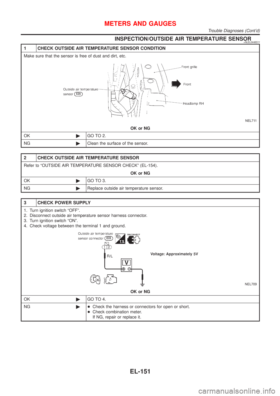
INSPECTION/OUTSIDE AIR TEMPERATURE SENSOR=NLEL0448S11
1 CHECK OUTSIDE AIR TEMPERATURE SENSOR CONDITION
Make sure that the sensor is free of dust and dirt, etc.
NEL711
OK or NG
OK©GO TO 2.
NG©Clean the surface of the sensor.
2 CHECK OUTSIDE AIR TEMPERATURE SENSOR
Refer to ªOUTSIDE AIR TEMPERATURE SENSOR CHECKº (EL-154).
OK or NG
OK©GO TO 3.
NG©Replace outside air temperature sensor.
3 CHECK POWER SUPPLY
1. Turn ignition switch ªOFFº.
2. Disconnect outside air temperature sensor harness connector.
3. Turn ignition switch ªONº.
4. Check voltage between the terminal 1 and ground.
NEL709
OK or NG
OK©GO TO 4.
NG©+Check the harness or connectors for open or short.
+Check combination meter.
If NG, repair or replace it.
METERS AND GAUGES
Trouble Diagnoses (Cont'd)
EL-151
Page 1936 of 3051
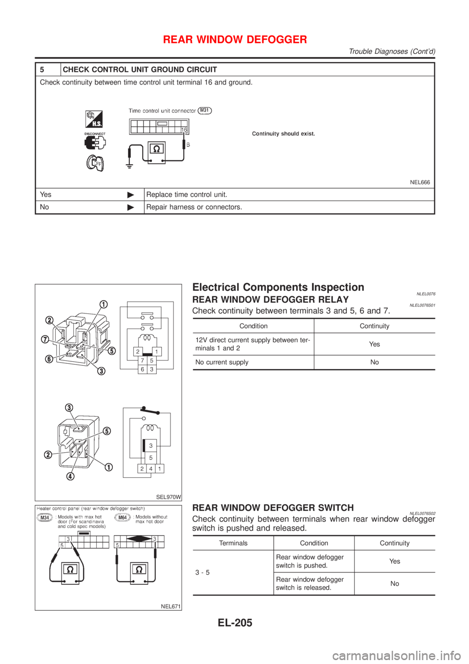
5 CHECK CONTROL UNIT GROUND CIRCUIT
Check continuity between time control unit terminal 16 and ground.
NEL666
Ye s©Replace time control unit.
No©Repair harness or connectors.
SEL970W
Electrical Components InspectionNLEL0076REAR WINDOW DEFOGGER RELAYNLEL0076S01Check continuity between terminals 3 and 5, 6 and 7.
Condition Continuity
12V direct current supply between ter-
minals 1 and 2Ye s
No current supply No
NEL671
REAR WINDOW DEFOGGER SWITCHNLEL0076S02Check continuity between terminals when rear window defogger
switch is pushed and released.
Terminals Condition Continuity
3-5Rear window defogger
switch is pushed.Ye s
Rear window defogger
switch is released.No
REAR WINDOW DEFOGGER
Trouble Diagnoses (Cont'd)
EL-205
Page 1961 of 3051
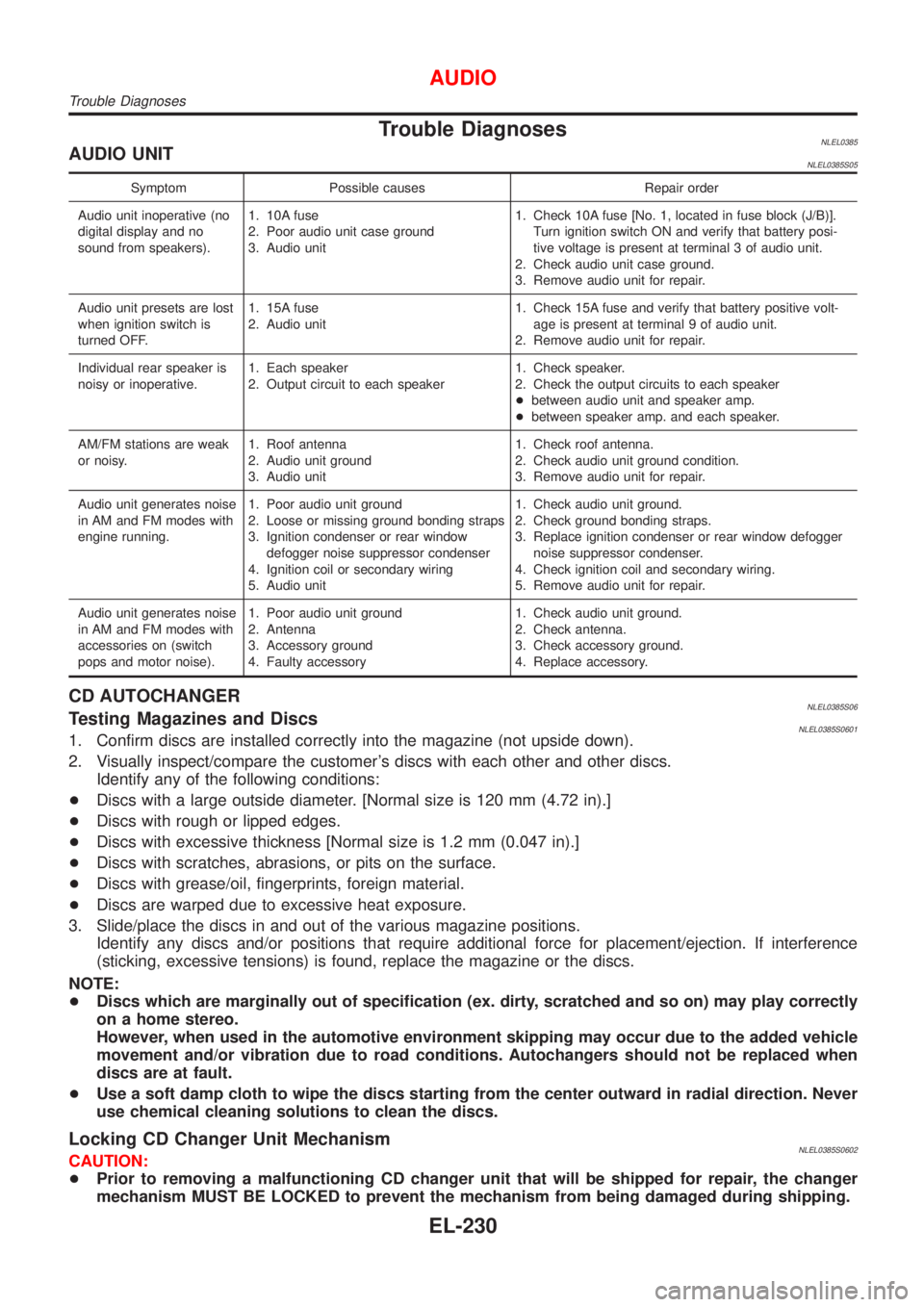
Trouble DiagnosesNLEL0385AUDIO UNITNLEL0385S05
Symptom Possible causes Repair order
Audio unit inoperative (no
digital display and no
sound from speakers).1. 10A fuse
2. Poor audio unit case ground
3. Audio unit1. Check 10A fuse [No. 1, located in fuse block (J/B)].
Turn ignition switch ON and verify that battery posi-
tive voltage is present at terminal 3 of audio unit.
2. Check audio unit case ground.
3. Remove audio unit for repair.
Audio unit presets are lost
when ignition switch is
turned OFF.1. 15A fuse
2. Audio unit1. Check 15A fuse and verify that battery positive volt-
age is present at terminal 9 of audio unit.
2. Remove audio unit for repair.
Individual rear speaker is
noisy or inoperative.1. Each speaker
2. Output circuit to each speaker1. Check speaker.
2. Check the output circuits to each speaker
+between audio unit and speaker amp.
+between speaker amp. and each speaker.
AM/FM stations are weak
or noisy.1. Roof antenna
2. Audio unit ground
3. Audio unit1. Check roof antenna.
2. Check audio unit ground condition.
3. Remove audio unit for repair.
Audio unit generates noise
in AM and FM modes with
engine running.1. Poor audio unit ground
2. Loose or missing ground bonding straps
3. Ignition condenser or rear window
defogger noise suppressor condenser
4. Ignition coil or secondary wiring
5. Audio unit1. Check audio unit ground.
2. Check ground bonding straps.
3. Replace ignition condenser or rear window defogger
noise suppressor condenser.
4. Check ignition coil and secondary wiring.
5. Remove audio unit for repair.
Audio unit generates noise
in AM and FM modes with
accessories on (switch
pops and motor noise).1. Poor audio unit ground
2. Antenna
3. Accessory ground
4. Faulty accessory1. Check audio unit ground.
2. Check antenna.
3. Check accessory ground.
4. Replace accessory.
CD AUTOCHANGERNLEL0385S06Testing Magazines and DiscsNLEL0385S06011. Confirm discs are installed correctly into the magazine (not upside down).
2. Visually inspect/compare the customer's discs with each other and other discs.
Identify any of the following conditions:
+Discs with a large outside diameter. [Normal size is 120 mm (4.72 in).]
+Discs with rough or lipped edges.
+Discs with excessive thickness [Normal size is 1.2 mm (0.047 in).]
+Discs with scratches, abrasions, or pits on the surface.
+Discs with grease/oil, fingerprints, foreign material.
+Discs are warped due to excessive heat exposure.
3. Slide/place the discs in and out of the various magazine positions.
Identify any discs and/or positions that require additional force for placement/ejection. If interference
(sticking, excessive tensions) is found, replace the magazine or the discs.
NOTE:
+Discs which are marginally out of specification (ex. dirty, scratched and so on) may play correctly
on a home stereo.
However, when used in the automotive environment skipping may occur due to the added vehicle
movement and/or vibration due to road conditions. Autochangers should not be replaced when
discs are at fault.
+Use a soft damp cloth to wipe the discs starting from the center outward in radial direction. Never
use chemical cleaning solutions to clean the discs.
Locking CD Changer Unit MechanismNLEL0385S0602CAUTION:
+Prior to removing a malfunctioning CD changer unit that will be shipped for repair, the changer
mechanism MUST BE LOCKED to prevent the mechanism from being damaged during shipping.
AUDIO
Trouble Diagnoses
EL-230
Page 2101 of 3051
PrecautionsNLEL0510WARNING:
Do not attempt to disassemble the monitor. Parts of the monitor have high voltages that can result in
severe and dangerous electric shock.
CAUTION:
+Do not reverse battery connections.
+Do not attach unauthorized parts.
+Protect the unit from severe impact.
NOTE:
Before beginning repair, determine whether or not the unit is defective. Refer to ªThis Condition Is Not
Abnormalº (EL-432).
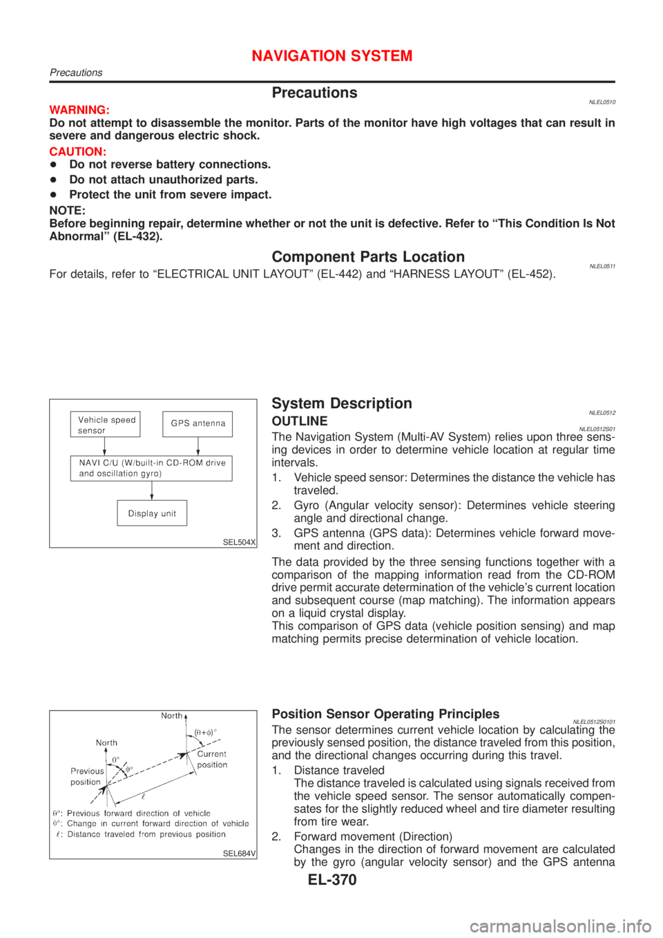
Component Parts LocationNLEL0511For details, refer to ªELECTRICAL UNIT LAYOUTº (EL-442) and ªHARNESS LAYOUTº (EL-452).
SEL504X
System DescriptionNLEL0512OUTLINENLEL0512S01The Navigation System (Multi-AV System) relies upon three sens-
ing devices in order to determine vehicle location at regular time
intervals.
1. Vehicle speed sensor: Determines the distance the vehicle has
traveled.
2. Gyro (Angular velocity sensor): Determines vehicle steering
angle and directional change.
3. GPS antenna (GPS data): Determines vehicle forward move-
ment and direction.
The data provided by the three sensing functions together with a
comparison of the mapping information read from the CD-ROM
drive permit accurate determination of the vehicle's current location
and subsequent course (map matching). The information appears
on a liquid crystal display.
This comparison of GPS data (vehicle position sensing) and map
matching permits precise determination of vehicle location.
SEL684V
Position Sensor Operating PrinciplesNLEL0512S0101The sensor determines current vehicle location by calculating the
previously sensed position, the distance traveled from this position,
and the directional changes occurring during this travel.
1. Distance traveled
The distance traveled is calculated using signals received from
the vehicle speed sensor. The sensor automatically compen-
sates for the slightly reduced wheel and tire diameter resulting
from tire wear.
2. Forward movement (Direction)
Changes in the direction of forward movement are calculated
by the gyro (angular velocity sensor) and the GPS antenna
NAVIGATION SYSTEM
Precautions
EL-370
Page 2163 of 3051
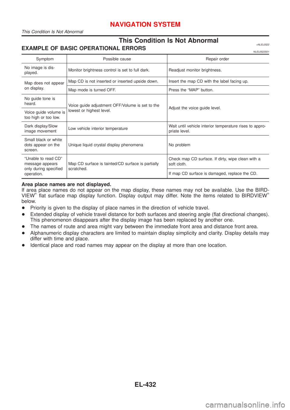
This Condition Is Not Abnormal=NLEL0522EXAMPLE OF BASIC OPERATIONAL ERRORSNLEL0522S01
Symptom Possible cause Repair order
No image is dis-
played.Monitor brightness control is set to full dark. Readjust monitor brightness.
Map does not appear
on display.Map CD is not inserted or inserted upside down. Insert the map CD with the label facing up.
Map mode is turned OFF. Press the ªMAPº button.
No guide tone is
heard.
Voice guide adjustment OFF/Volume is set to the
lowest or highest level.Adjust the voice guide level.
Voice guide volume is
too high or too low.
Dark display/Slow
image movementLow vehicle interior temperatureWait until vehicle interior temperature rises to appro-
priate level.
Small black or white
dots appear on the
screen.Unique liquid crystal display phenomena No problem
ªUnable to read CDº
message appears
only during specified
operation.Map CD surface is tainted/CD surface is partially
scratched.Check map CD surface. If dirty, wipe clean with a
soft cloth.
If map CD surface is damaged, replace the CD.
Area place names are not displayed.
If area place names do not appear on the map display, these names may not be available. Use the BIRD-
VIEW
Tflat surface map display function. Display output may differ. Note the items related to BIRDVIEWT
below.
+Priority is given to the display of place names in the direction of vehicle travel.
+Extended display of vehicle travel distance for both surfaces and steering angle (flat directional changes).
This phenomenon disappears after the display image has been replaced by another one.
+The names of route and area might vary between the immediate front area and distance front area.
+Alphanumeric display characters are limited to maintain display simplicity and clarity. Display details may
differ with time and place.
+Identical place and road names may appear on the display at more than one location.
NAVIGATION SYSTEM
This Condition Is Not Abnormal
EL-432
Page 2170 of 3051
+The enlarged intersection map may display a ªUnknown streetº message at some street intersections.
+Because of road configuration, etc. the guide may finish early. If this occurs, follow the marker to reach
your destination.
+Destination area side information (left side and right side) may differ from actual conditions because of
data error.
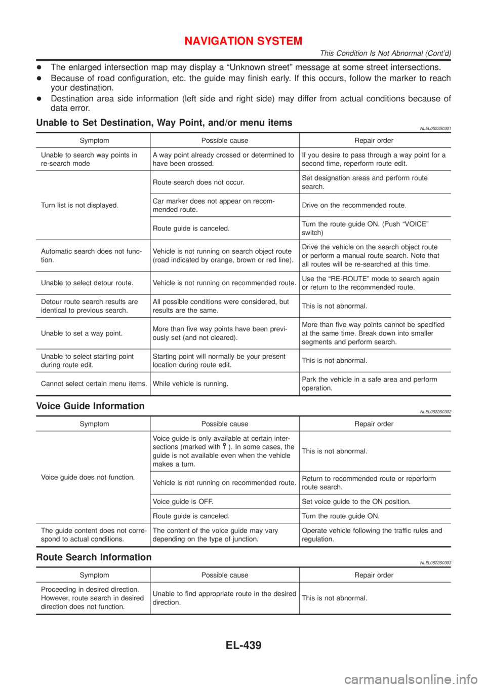
Unable to Set Destination, Way Point, and/or menu itemsNLEL0522S0301
Symptom Possible cause Repair order
Unable to search way points in
re-search modeA way point already crossed or determined to
have been crossed.If you desire to pass through a way point for a
second time, reperform route edit.
Turn list is not displayed.Route search does not occur.Set designation areas and perform route
search.
Car marker does not appear on recom-
mended route.Drive on the recommended route.
Route guide is canceled.Turn the route guide ON. (Push ªVOICEº
switch)
Automatic search does not func-
tion.Vehicle is not running on search object route
(road indicated by orange, brown or red line).Drive the vehicle on the search object route
or perform a manual route search. Note that
all routes will be re-searched at this time.
Unable to select detour route. Vehicle is not running on recommended route.Use the ªRE-ROUTEº mode to search again
or return to the recommended route.
Detour route search results are
identical to previous search.All possible conditions were considered, but
results are the same.This is not abnormal.
Unable to set a way point.More than five way points have been previ-
ously set (and not cleared).More than five way points cannot be specified
at the same time. Break down into smaller
segments and perform search.
Unable to select starting point
during route edit.Starting point will normally be your present
location during route edit.This is not abnormal.
Cannot select certain menu items. While vehicle is running.Park the vehicle in a safe area and perform
operation.
Voice Guide InformationNLEL0522S0302
Symptom Possible cause Repair order
Voice guide does not function.Voice guide is only available at certain inter-
sections (marked with
). In some cases, the
guide is not available even when the vehicle
makes a turn.This is not abnormal.
Vehicle is not running on recommended route.Return to recommended route or reperform
route search.
Voice guide is OFF. Set voice guide to the ON position.
Route guide is canceled. Turn the route guide ON.
The guide content does not corre-
spond to actual conditions.The content of the voice guide may vary
depending on the type of junction.Operate vehicle following the traffic rules and
regulation.
Route Search InformationNLEL0522S0303
Symptom Possible cause Repair order
Proceeding in desired direction.
However, route search in desired
direction does not function.Unable to find appropriate route in the desired
direction.This is not abnormal.
NAVIGATION SYSTEM
This Condition Is Not Abnormal (Cont'd)
EL-439