Page 1568 of 3051

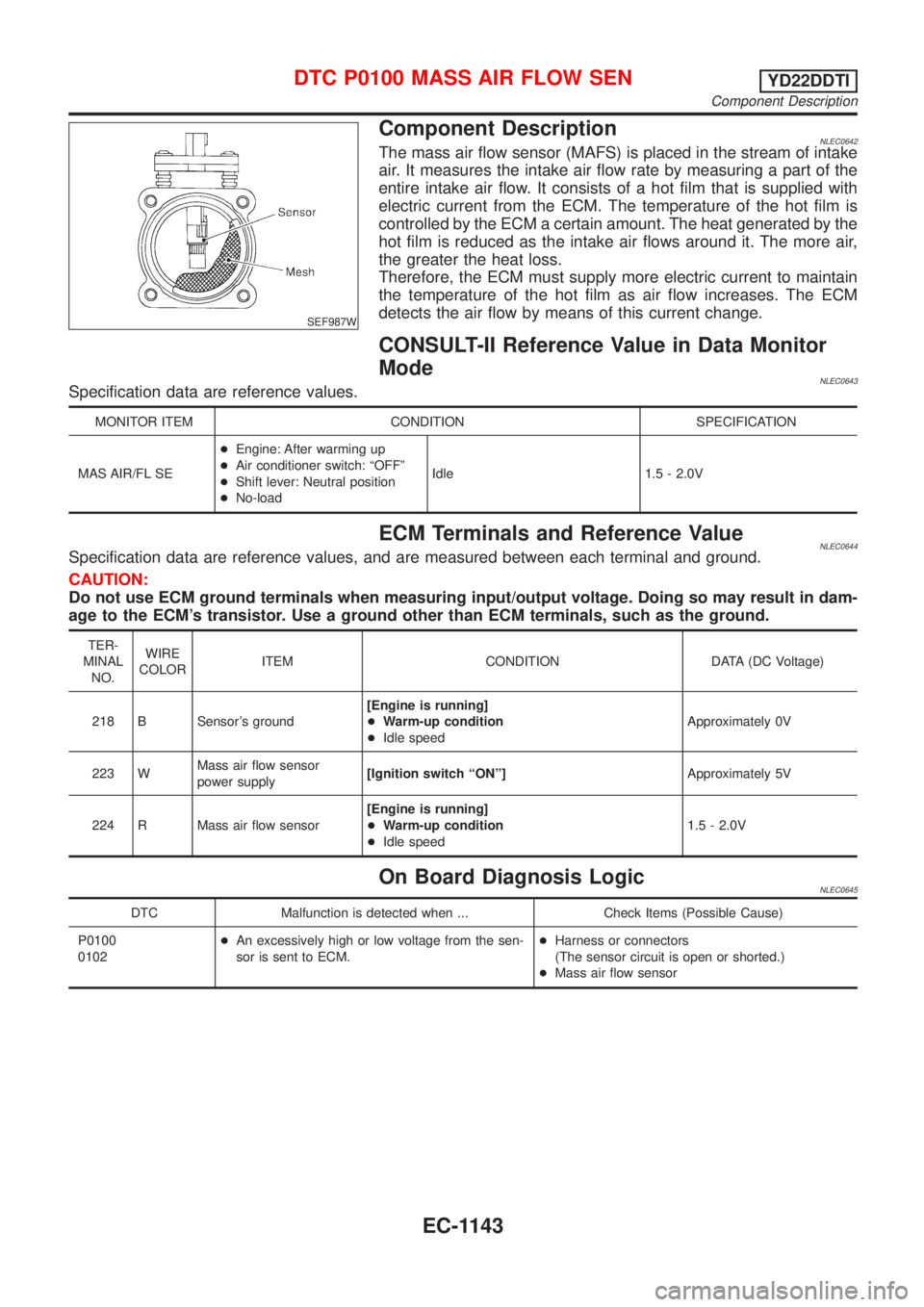
SEF987W
Component DescriptionNLEC0642The mass air flow sensor (MAFS) is placed in the stream of intake
air. It measures the intake air flow rate by measuring a part of the
entire intake air flow. It consists of a hot film that is supplied with
electric current from the ECM. The temperature of the hot film is
controlled by the ECM a certain amount. The heat generated by the
hot film is reduced as the intake air flows around it. The more air,
the greater the heat loss.
Therefore, the ECM must supply more electric current to maintain
the temperature of the hot film as air flow increases. The ECM
detects the air flow by means of this current change.
CONSULT-II Reference Value in Data Monitor
Mode
NLEC0643Specification data are reference values.
MONITOR ITEM CONDITION SPECIFICATION
MAS AIR/FL SE+Engine: After warming up
+Air conditioner switch: ªOFFº
+Shift lever: Neutral position
+No-loadIdle 1.5 - 2.0V
ECM Terminals and Reference ValueNLEC0644Specification data are reference values, and are measured between each terminal and ground.
CAUTION:
Do not use ECM ground terminals when measuring input/output voltage. Doing so may result in dam-
age to the ECM's transistor. Use a ground other than ECM terminals, such as the ground.
TER-
MINAL
NO.WIRE
COLORITEM CONDITION DATA (DC Voltage)
218 B Sensor's ground[Engine is running]
+Warm-up condition
+Idle speedApproximately 0V
223 WMass air flow sensor
power supply[Ignition switch ªONº]Approximately 5V
224 R Mass air flow sensor[Engine is running]
+Warm-up condition
+Idle speed1.5 - 2.0V
On Board Diagnosis LogicNLEC0645
DTC Malfunction is detected when ... Check Items (Possible Cause)
P0100
0102+An excessively high or low voltage from the sen-
sor is sent to ECM.+Harness or connectors
(The sensor circuit is open or shorted.)
+Mass air flow sensor
DTC P0100 MASS AIR FLOW SENYD22DDTI
Component Description
EC-1143
Page 1590 of 3051
14 DETECT MALFUNCTIONING PART
Check the following.
+Harness connectors F24, M50 (where fitted)
+Harness connectors M72, F44 (where fitted)
+Harness for open or short between ECM and accelerator work unit
©Repair open circuit or short to ground or short to power in harness or connectors.
15 CHECK ACCELERATOR POSITION SWITCH
Check continuity between accelerator position switch terminals 1 and 3 under the following conditions.
SEF913Y
OK or NG
OK©GO TO 16.
NG©Replace accelerator pedal assembly.
16 CHECK INTERMITTENT INCIDENT
Refer to ªTROUBLE DIAGNOSIS FOR INTERMITTENT INCIDENTº, EC-1135.
©INSPECTION END
DTC P0120 ACCEL POS SENSORYD22DDTI
Diagnostic Procedure (Cont'd)
EC-1165
Page 1607 of 3051
4 CHECK STOP LAMP SWITCH INPUT SIGNAL CIRCUIT FOR OPEN AND SHORT
1. Turn ignition switch ªOFFº.
2. Disconnect ECM harness connector.
3. Disconnect stop lamp switch harness connector.
SEF751Z
4. Check harness continuity between ECM terminal 405 and stop lamp switch terminal 2. Refer to Wiring Diagram.
Continuity should exist.
5. Also check harness for short to ground and short to power.
OK or NG
OK©GO TO 6.
NG©GO TO 5.
5 DETECT MALFUNCTIONING PART
Check the following.
+Harness connectors M50, F24 (where fitted)
+Harness connectors M72, F44 (where fitted)
+Harness for open or short between ECM and stop lamp switch
©Repair open circuit or short to ground or short to power in harness or connectors.
6 CHECK STOP LAMP SWITCH
Check continuity between stop lamp switch terminals 1 and 2 under the following conditions.
SEF753Z
OK or NG
OK©GO TO 7.
NG©Replace stop lamp switch.
DTC P0571 BRAKE SWYD22DDTI
Diagnostic Procedure (Cont'd)
EC-1182
Page 1609 of 3051
10 DETECT MALFUNCTIONING PART
Check the following.
+Harness connectors M50, F24 (where fitted)
+Harness connectors M72, F44 (where fitted)
+Harness for open or short between ECM and brake pedal position switch
©Repair open circuit or short to ground or short to power in harness or connectors.
11 CHECK BRAKE PEDAL POSITION SWITCH
Check continuity between brake pedal position switch terminals 1 and 2 under the following conditions.
SEF754Z
OK or NG
OK©GO TO 12.
NG©Replace brake pedal position switch.
12 CHECK INTERMITTENT INCIDENT
Refer to ªTROUBLE DIAGNOSIS FOR INTERMITTENT INCIDENTº, EC-1135.
©INSPECTION END
DTC P0571 BRAKE SWYD22DDTI
Diagnostic Procedure (Cont'd)
EC-1184
Page 1626 of 3051

DescriptionNLEC0660SYSTEM DESCRIPTIONNLEC0660S01
Sensor Input signal to ECM ECM function Actuator
Vehicle speed sensor Vehicle speed
Cooling fan
controlCooling fan relay Engine coolant temperature sensor Engine coolant temperature
Air conditioner switch Air conditioner ªONº signal
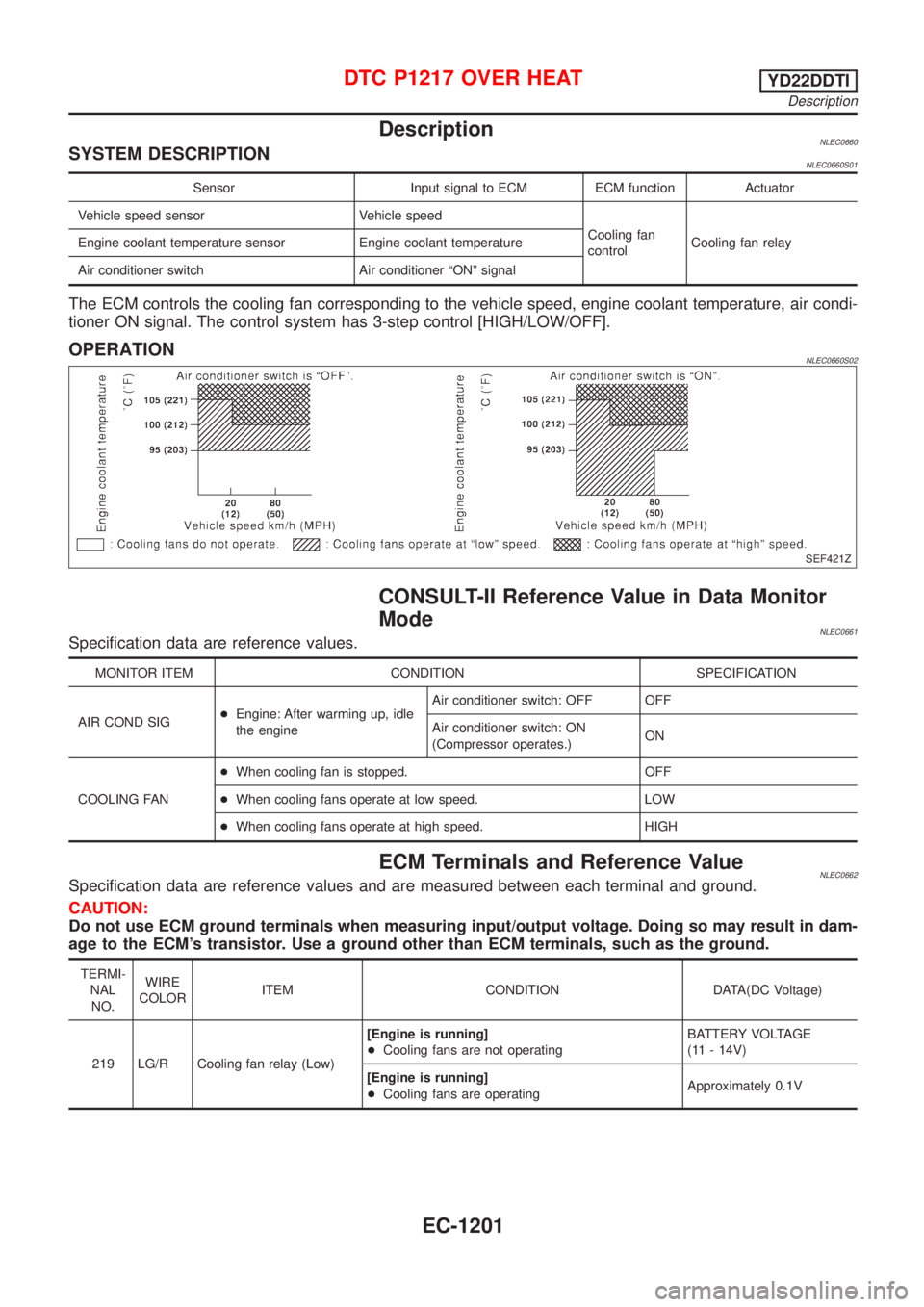
The ECM controls the cooling fan corresponding to the vehicle speed, engine coolant temperature, air condi-
tioner ON signal. The control system has 3-step control [HIGH/LOW/OFF].
OPERATIONNLEC0660S02
SEF421Z
CONSULT-II Reference Value in Data Monitor
Mode
NLEC0661Specification data are reference values.
MONITOR ITEM CONDITION SPECIFICATION
AIR COND SIG+Engine: After warming up, idle
the engineAir conditioner switch: OFF OFF
Air conditioner switch: ON
(Compressor operates.)ON
COOLING FAN+When cooling fan is stopped. OFF
+When cooling fans operate at low speed. LOW
+When cooling fans operate at high speed. HIGH
ECM Terminals and Reference ValueNLEC0662Specification data are reference values and are measured between each terminal and ground.
CAUTION:
Do not use ECM ground terminals when measuring input/output voltage. Doing so may result in dam-
age to the ECM's transistor. Use a ground other than ECM terminals, such as the ground.
TERMI-
NAL
NO.WIRE
COLORITEM CONDITION DATA(DC Voltage)
219 LG/R Cooling fan relay (Low)[Engine is running]
+Cooling fans are not operatingBATTERY VOLTAGE
(11 - 14V)
[Engine is running]
+Cooling fans are operatingApproximately 0.1V
DTC P1217 OVER HEATYD22DDTI
Description
EC-1201
Page 1628 of 3051

AEC640
SEF111X
SEC163BA
MEC475B
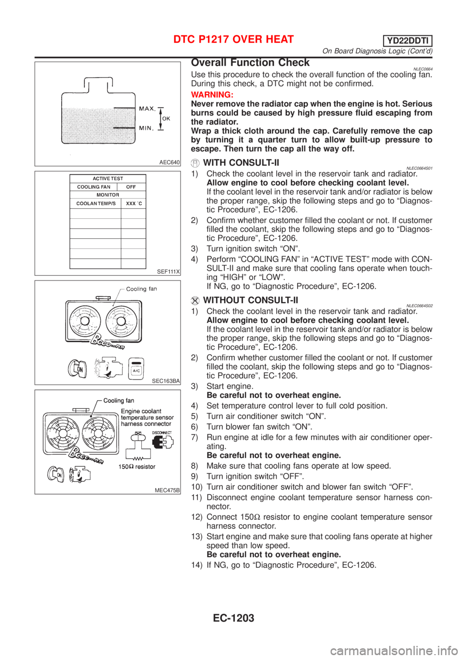
Overall Function CheckNLEC0664Use this procedure to check the overall function of the cooling fan.
During this check, a DTC might not be confirmed.
WARNING:
Never remove the radiator cap when the engine is hot. Serious
burns could be caused by high pressure fluid escaping from
the radiator.
Wrap a thick cloth around the cap. Carefully remove the cap
by turning it a quarter turn to allow built-up pressure to
escape. Then turn the cap all the way off.
WITH CONSULT-IINLEC0664S011) Check the coolant level in the reservoir tank and radiator.
Allow engine to cool before checking coolant level.
If the coolant level in the reservoir tank and/or radiator is below
the proper range, skip the following steps and go to ªDiagnos-
tic Procedureº, EC-1206.
2) Confirm whether customer filled the coolant or not. If customer
filled the coolant, skip the following steps and go to ªDiagnos-
tic Procedureº, EC-1206.
3) Turn ignition switch ªONº.
4) Perform ªCOOLING FANº in ªACTIVE TESTº mode with CON-
SULT-II and make sure that cooling fans operate when touch-
ing ªHIGHº or ªLOWº.
If NG, go to ªDiagnostic Procedureº, EC-1206.
WITHOUT CONSULT-IINLEC0664S021) Check the coolant level in the reservoir tank and radiator.
Allow engine to cool before checking coolant level.
If the coolant level in the reservoir tank and/or radiator is below
the proper range, skip the following steps and go to ªDiagnos-
tic Procedureº, EC-1206.
2) Confirm whether customer filled the coolant or not. If customer
filled the coolant, skip the following steps and go to ªDiagnos-
tic Procedureº, EC-1206.
3) Start engine.
Be careful not to overheat engine.
4) Set temperature control lever to full cold position.
5) Turn air conditioner switch ªONº.
6) Turn blower fan switch ªONº.
7) Run engine at idle for a few minutes with air conditioner oper-
ating.
Be careful not to overheat engine.
8) Make sure that cooling fans operate at low speed.
9) Turn ignition switch ªOFFº.
10) Turn air conditioner switch and blower fan switch ªOFFº.
11) Disconnect engine coolant temperature sensor harness con-
nector.
12) Connect 150Wresistor to engine coolant temperature sensor
harness connector.
13) Start engine and make sure that cooling fans operate at higher
speed than low speed.
Be careful not to overheat engine.
14) If NG, go to ªDiagnostic Procedureº, EC-1206.
DTC P1217 OVER HEATYD22DDTI
On Board Diagnosis Logic (Cont'd)
EC-1203
Page 1633 of 3051
4 CHECK COOLING FAN LOW SPEED OPERATION
Without CONSULT-II
1. Disconnect cooling fan relay-3.
SEF871Z
2. Start engine and let it idle.
3. Set temperature lever at full cold position.
4. Turn air conditioner switch ªONº.
5. Turn blower fan switch ªONº.
6. Make sure that cooling fans-1 and -2 operate at low speed.
SEC163BA
OK or NG
OK©GO TO 5.
NG©Check cooling fan low speed control circuit. (Go to PROCEDURE A, EC-1211.)
DTC P1217 OVER HEATYD22DDTI
Diagnostic Procedure (Cont'd)
EC-1208
Page 1634 of 3051

5 CHECK COOLING FAN HIGH SPEED OPERATION
Without CONSULT-II
1. Turn ignition switch ªOFFº.
2. Reconnect cooling fan relay-3.
3. Turn air conditioner switch and blower fan switch ªOFFº.
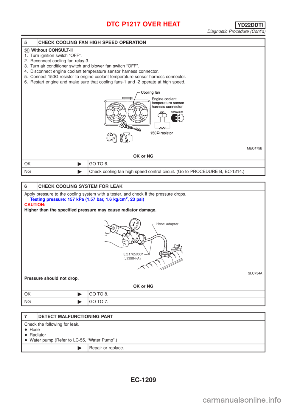
4. Disconnect engine coolant temperature sensor harness connector.
5. Connect 150Wresistor to engine coolant temperature sensor harness connector.
6. Restart engine and make sure that cooling fans-1 and -2 operate at high speed.
MEC475B
OK or NG
OK©GO TO 6.
NG©Check cooling fan high speed control circuit. (Go to PROCEDURE B, EC-1214.)
6 CHECK COOLING SYSTEM FOR LEAK
Apply pressure to the cooling system with a tester, and check if the pressure drops.
Testing pressure: 157 kPa (1.57 bar, 1.6 kg/cm2, 23 psi)
CAUTION:
Higher than the specified pressure may cause radiator damage.
SLC754A
Pressure should not drop.
OK or NG
OK©GO TO 8.
NG©GO TO 7.
7 DETECT MALFUNCTIONING PART
Check the following for leak.
+Hose
+Radiator
+Water pump (Refer to LC-55, ªWater Pumpº.)
©Repair or replace.
DTC P1217 OVER HEATYD22DDTI
Diagnostic Procedure (Cont'd)
EC-1209