2001 NISSAN ALMERA TINO charging
[x] Cancel search: chargingPage 2601 of 3051

HFC-134a (R-134a) Service Tools and
Equipment
=NLHA0120Never mix HFC-134a refrigerant and/or its specified lubricant with CFC-12 (R-12) refrigerant and/or its lubri-
cant.
Separate and non-interchangeable service equipment must be used for handling each type of refrigerant/
lubricant.
Refrigerant container fittings, service hose fittings and service equipment fittings (equipment which handles
refrigerant and/or lubricant) are different between CFC-12 (R-12) and HFC-134a (R-134a). This is to avoid
mixed use of the refrigerants/lubricant.
Adapters that convert one size fitting to another must never be used: refrigerant/lubricant contamination will
occur and compressor failure will result.
Tool number
Tool nameDescription
HFC-134a (R-134a)
refrigerant
NT196
Container color: Light blue
Container marking: HFC-134a (R-134a)
Fitting size: Thread size
+Large container 1/2″-16 ACME
KLH00-PAGR0
Nissan A/C System Oil
Type R
KLH00-PAGS0
Nissan A/C System Oil
Type S
NT197
Type: Poly alkylene glycol oil (PAG), type R
Application: HFC-134a (R-134a) vane rotary com-
pressors (Nissan only)
Type S
Application: HFC-134a (R-134a) swash plate com-
pressors (Nissan only)
Lubricity: 40 m!(1.4 Imp fl oz)
Recovery/Recycling
Recharging equipment
(ACR4)
NT195
Function: Refrigerant Recovery and Recycling and
Recharging
Electrical leak detector
NT198
Power supply:
+DC 12V (Cigarette lighter)
Manifold gauge set (with
hoses and couplers)
NT199
Identification:
+The gauge face indicates R-134a.
Fitting size: Thread size
+1/2″-16 ACME
PREPARATION
HFC-134a (R-134a) Service Tools and Equipment
HA-10
Page 2676 of 3051

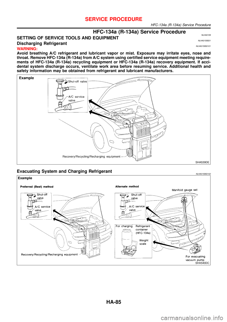
HFC-134a (R-134a) Service ProcedureNLHA0159SETTING OF SERVICE TOOLS AND EQUIPMENTNLHA0159S01Discharging RefrigerantNLHA0159S0101WARNING:
Avoid breathing A/C refrigerant and lubricant vapor or mist. Exposure may irritate eyes, nose and
throat. Remove HFC-134a (R-134a) from A/C system using certified service equipment meeting require-
ments of HFC-134a (R-134a) recycling equipment or HFC-134a (R-134a) recovery equipment. If acci-
dental system discharge occurs, ventilate work area before resuming service. Additional health and
safety information may be obtained from refrigerant and lubricant manufacturers.
SHA539DE
Evacuating System and Charging RefrigerantNLHA0159S0102
SHA540DC
SERVICE PROCEDURE
HFC-134a (R-134a) Service Procedure
HA-85
Page 2680 of 3051

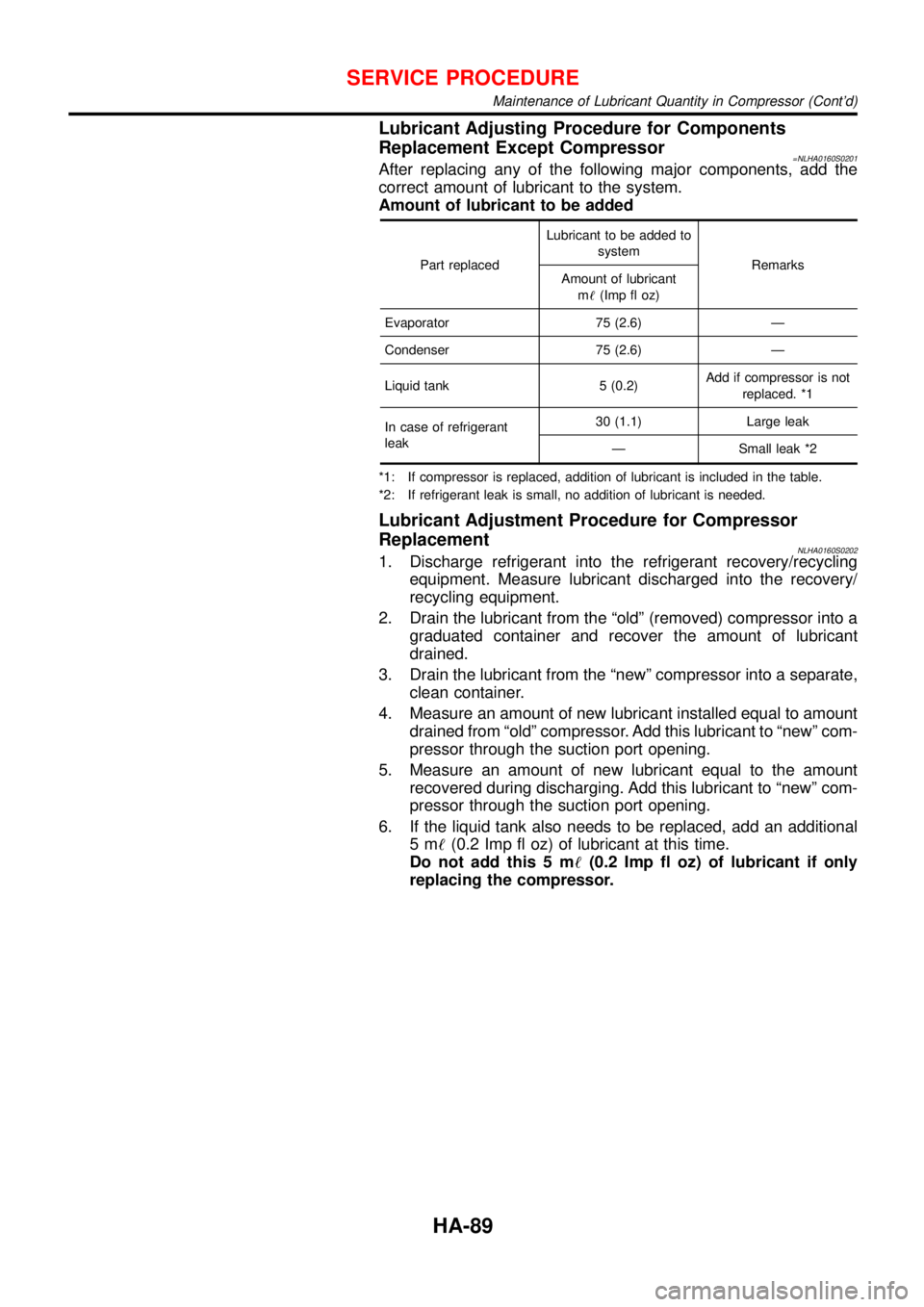
Lubricant Adjusting Procedure for Components
Replacement Except Compressor
=NLHA0160S0201After replacing any of the following major components, add the
correct amount of lubricant to the system.
Amount of lubricant to be added
Part replacedLubricant to be added to
system
Remarks
Amount of lubricant
m!(Imp fl oz)
Evaporator 75 (2.6)—
Condenser 75 (2.6)—
Liquid tank 5 (0.2)Add if compressor is not
replaced. *1
In case of refrigerant
leak30 (1.1) Large leak
—Small leak *2
*1: If compressor is replaced, addition of lubricant is included in the table.
*2: If refrigerant leak is small, no addition of lubricant is needed.
Lubricant Adjustment Procedure for Compressor
Replacement
NLHA0160S02021. Discharge refrigerant into the refrigerant recovery/recycling
equipment. Measure lubricant discharged into the recovery/
recycling equipment.
2. Drain the lubricant from the“old”(removed) compressor into a
graduated container and recover the amount of lubricant
drained.
3. Drain the lubricant from the“new”compressor into a separate,
clean container.
4. Measure an amount of new lubricant installed equal to amount
drained from“old”compressor. Add this lubricant to“new”com-
pressor through the suction port opening.
5. Measure an amount of new lubricant equal to the amount
recovered during discharging. Add this lubricant to“new”com-
pressor through the suction port opening.
6. If the liquid tank also needs to be replaced, add an additional
5m!(0.2 Imp fl oz) of lubricant at this time.
Do not add this 5 m!(0.2 Imp fl oz) of lubricant if only
replacing the compressor.
SERVICE PROCEDURE
Maintenance of Lubricant Quantity in Compressor (Cont’d)
HA-89
Page 2698 of 3051

Canister - See EVAP canister .......... EC-39, 573
Charging system ....................................... SC-24
Cigarette lighter ....................................... EL-195
Circuit breaker ........................................... EL-32
Closed throttle position switch ....... EC-352, 872
Clutch cover .............................................. CL-22
Clutch disc ................................................. CL-22
Clutch master cylinder ............................... CL-11
Clutch operating cylinder ........................... CL-14
Clutch pedal .............................................. CL-10
Clutch release bearing ........................ CL-17, 20
Clutch release mechanism .................. CL-17, 20
Clutch withdrawal lever ....................... CL-17, 20
Coil spring (front) ...................................... SU-10
Coil spring (rear) ....................................... SU-23
Collision diagnosis .................................... RS-66
Combination lamp, rear, removal and
installation .............................................. BT-38
Combination meter removal and instal-
lation - See Instrument panel ................ BT-22
Combination meter .................................. EL-130
Combination switch ................................... EL-64
Compression pressure ........................... EM-164
Compressor clutch removal and
installation .............................................. HA-90
Compressor precaution ............................... HA-5
Compressor special service tool ................. HA-9
Connecting rod bearing clearance .. EM-58, 140,
232
Connecting rod bushing clearance .. EM-59, 141,
234
Connecting rod ......................... EM-55, 136, 227
Console box - See Instrument panel ......... BT-22
Control lever (M/T) .................................... MT-23
Converter housing installation ................. AT-207
Coolant mixture ratio ................................ MA-22
Cooling circuit (engine) ................. LC-12, 32, 53
Cooling fan control system ........................ LC-59
Cooling fan control ............... EC-373, 882, 1201
Cooling fan motor ........................... EC-385, 899
Cooling fan relay ............................. EC-384, 898
Coupling sleeve (M/T) ........................ MT-25, 63
Crank angle sensor built into distribu-
tor - See Camshaft position
sensor .................................................. EC-825
Crankcase emission control system -
See Positive crankcase ventilation ...... EC-42,
576, 1082
Crankcase ventilation system - See
Positive crankcase ventilation ...... EC-42, 576,
1082
Crankshaft position sensor (OBD) . EC-295, 439,
819, 969
Crankshaft position sensor (POS) .. EC-295, 439
Crankshaft position sensor (TDC) ......... EC-1166
Crankshaft ................................ EM-57, 138, 229
Cylinder block ........................... EM-52, 133, 221
Cylinder head ........................... EM-33, 108, 200D
DEF - Wiring diagram .............................. EL-199
DTC work support ............................. EC-91, 615
Data link connector for Consult ....... EC-43, 577,
1102
Daytime light system ................................. EL-73
Detonation sensor - See Knock
sensor .......................................... EC-291, 815
Diagnosis sensor unit ............................... RS-21
Diagnostic trouble code (DTC) for
OBD system ................... EC-16, 70, 550, 595,
1064, 1096
Diagnostic trouble code (DTC) inspec-
tion priority chart ......................... EC-122, 646
Differential gear (FF M/T) ............. MT-25, 63, 77
Dimensions ................................................. GI-41
Dome light - See Interior lamp ................ EL-116
Door glass ................................................. BT-14
Door lock ................................................... BT-18
Door mirror ................................................ BT-63
Door trim .................................................... BT-32
Door, front .................................................. BT-13
Door, rear ................................................... BT-13
Drive plate runout ..................... EM-60, 142, 235
Drive shaft (front) ...................................... AX-10
Dropping resistor (A/T) .................... AT-103, 163
Dual pressure switch ................................ HA-12
E
ECCS-D control module ... EC-1129, 1177, 1185,
1253, 1255, 1260, 1262
ECM input/output signal ........ EC-133, 657, 1129
ECTS - Wiring diagram ......... EC-171, 696, 1150
EGR control valve ................................... EC-400
EGR temperature sensor ................ EC-386, 915
EGR volume control valve ............ EC-319, 1277
EGR/TS - Wiring diagram ............... EC-389, 918
EGRC/V - Wiring diagram ....................... EC-322
EGRC1 - Wiring diagram ....... EC-314, 397, 449,
838, 925, 978, 1279
EVAP canister purge volume control
solenoid valve ............................... EC-40, 574
EVAP canister purge volume control
valve ............................ EC-332, 458, 852, 986
EVAP canister ................................... EC-40, 574
Electric sunroof ........................................ EL-238
Electrical diagnoses ................................... GI-21
Electrical ignition system .................. EC-37, 571
Electrical load signal circuit .......... EC-535, 1050
Electrical unit ........................................... EL-530
Electrical units location ............................ EL-442
Electronic fuel injection pump .... EC-1087, 1187,
1194, 1218, 1225, 1232, 1239, 1246, 1264
Engine compartment ................................. BT-66
Engine control circuit diagram ......... EC-30, 564,
1074
ALPHABETICAL INDEX
IDX-3
Page 2938 of 3051
![NISSAN ALMERA TINO 2001 Service Repair Manual SRS701
If no malfunction is detected on“SELF-DIAG [CURRENT]”but mal-
function is indicated by the“AIR BAG”warning lamp, go to DIAG-
NOSTIC PROCEDURE 4, page RS-51, to diagnose the following
si NISSAN ALMERA TINO 2001 Service Repair Manual SRS701
If no malfunction is detected on“SELF-DIAG [CURRENT]”but mal-
function is indicated by the“AIR BAG”warning lamp, go to DIAG-
NOSTIC PROCEDURE 4, page RS-51, to diagnose the following
si](/manual-img/5/57352/w960_57352-2937.png)
SRS701
If no malfunction is detected on“SELF-DIAG [CURRENT]”but mal-
function is indicated by the“AIR BAG”warning lamp, go to DIAG-
NOSTIC PROCEDURE 4, page RS-51, to diagnose the following
situations:
+Self-diagnostic result“SELF-DIAG [PAST]”(previously stored
in the memory) might not be erased after repair.
+The SRS system malfunctions intermittently.
8. Touch“PRINT”.
9. Compare diagnostic codes to“CONSULT-II Diagnostic Code
Chart”, page RS-47.
10. Touch“BACK”key of CONSULT-II until“SELECT SYSTEM”
appears in order to return to User mode from Diagnosis mode.
11. Turn ignition switch“OFF”, then turn off and disconnect
CONSULT-II, and disconnect both battery cables.
12. Repair the system as outlined by the“Repair order”in“CON-
SULT-II Diagnostic Code Chart”, that corresponds to the self-
diagnostic result. For replacement procedure of component
parts, refer to RS-21.
13. After repairing the system, go to DIAGNOSTIC PROCEDURE
3, page RS-49 for final checking.
CONSULT-II Diagnostic Code Chart (“SELF-DIAG
[CURRENT]”)
NLRS0048S0102
Diagnostic item ExplanationRepair order
“Recheck SRS at each replace-
ment.”
NO DTC IS
DETECTED.When malfunction is
indicated by the“AIR
BAG”warning lamp is
user mode.+Self-diagnostic result“SELF-DIAG
[PAST]”(previously stored in the
memory) might not be erased after
repair.
+Intermittent malfunction has been
detected in the past.+Go to DIAGNOSTIC PROCEDURE
4 (RS-49) after charging battery.
+No malfunction is detected.+Go to DIAGNOSTIC PROCEDURE
3 (RS-49).
AIRBAG MODULE
[OPEN]+Driver air bag module circuit is open. (including the spiral
cable)1. Visually check the wiring harness
connection.
2. Replace the harness if it has visible
damage.
3. Replace the spiral cable.
4. Replace driver air bag module.
(Before disposal of it, it must be
deployed.)
5. Replace the diagnosis sensor unit.
6. Replace the related harness. AIRBAG MODULE
[VB-SHORT]+Driver air bag module circuit is shorted to some power supply
circuit. (including the spiral cable)
AIRBAG MODULE
[GND-SHORT]+Driver air bag module circuit is shorted to ground. (including
the spiral cable)
AIRBAG MODULE
[SHORT]+Driver air bag module circuits are shorted to each other.
ASSIST A/B MODULE
[VB-SHORT]+Front passenger air bag module circuit is shorted to some
power supply circuit.1. Visually check the wiring harness
connection.
2. Replace the harness if it has visible
damage.
3. Replace front passenger air bag
module.
(Before disposal of it, it must be
deployed.)
4. Replace the diagnosis sensor unit.
5. Replace the related harness. ASSIST A/B MODULE
[OPEN]+Front passenger air bag module circuit is open.
ASSIST A/B MODULE
[GND-SHORT]+Front passenger air bag module circuit is shorted to ground.
ASSIST A/B MODULE
[SHORT]+Front passenger air bag module circuits are shorted to each
other.
SUPPLEMENTAL RESTRAINT SYSTEM (SRS)
Trouble Diagnoses with CONSULT-II (Cont’d)
RS-47
Page 2940 of 3051

Diagnostic item ExplanationRepair order
“Recheck SRS at each replace-
ment.”
CONTROL UNIT+Low battery voltage (Less than 9V)+Go to DIAGNOSTIC PROCEDURE
3 (RS-42) after charging battery.
+Diagnosis sensor unit is malfunctioning. 1. Visually check the wiring harness
connection.
2. Replace the harness if it has visible
damage.
3. Replace diagnosis sensor unit.
4. Replace the related harness.
* Follow the procedures in numerical order when repairing malfunctioning parts. Confirm whether malfunction is eliminated
using the air bag warning lamp or CONSULT-II each time repair is finished. If malfunction is still observed, proceed to the next
step. When malfunction is eliminated, further repair work is not required.
NRS122
DIAGNOSTIC PROCEDURE 3NLRS0048S02Final checking after repairing SRS by using CONSULT-II—
Diagnosis mode
1. After repairing SRS, connect both battery cables.
2. Connect CONSULT-II to data link connector.
3. Turn ignition switch from“OFF”to“ON”.
SRS695
4. Touch“START”.
C2SSE01
5. Touch“AIR BAG”.
SUPPLEMENTAL RESTRAINT SYSTEM (SRS)
Trouble Diagnoses with CONSULT-II (Cont’d)
RS-49
Page 2962 of 3051

STARTING & CHARGING SYSTEMS
SECTION
SC
CONTENTS
PRECAUTIONS...............................................................2
Supplemental Restraint System (SRS)″AIR
BAG″and″SEAT BELT PRE-TENSIONER″...............2
Wiring Diagrams and Trouble Diagnoses....................2
BATTERY.........................................................................3
How to Handle Battery ................................................3
METHODS OF PREVENTING OVER-DISCHARGE......3
CHECKING ELECTROLYTE LEVEL............................3
SPECIFIC GRAVITY CHECK......................................4
Battery Test and Charging Chart .................................6
CHART I...................................................................6
CHART II..................................................................7
A: SLOW CHARGE....................................................8
B: STANDARD CHARGE..........................................10
C: QUICK CHARGE................................................. 11
STARTING SYSTEM.....................................................13
System Description ....................................................13
M/T MODELS..........................................................13
A/T MODELS...........................................................13
Wiring Diagram - START -.........................................14
MODELS WITH FUSE AND FUSIBLE LINK BOX
E43
.........................................................................14
MODELS WITH FUSE AND FUSIBLE LINK BOX
E90
.........................................................................15
Trouble Diagnoses.....................................................16
Construction ...............................................................17
Removal and Installation ...........................................19
REMOVAL...............................................................19
INSTALLATION........................................................20
Inspection...................................................................20
MAGNETIC SWITCH CHECK...................................20
PINION/CLUTCH CHECK.........................................20
BRUSH CHECK.......................................................20
YOKE CHECK.........................................................21
ARMATURE CHECK................................................22
Assembly ...................................................................23
PINION PROTRUSION LENGTH ADJUSTMENT........23
CHARGING SYSTEM....................................................24
System Description ....................................................24
Wiring Diagram - CHARGE -.....................................25
MODELS WITH FUSE AND FUSIBLE LINK BOX
E43
.........................................................................25
MODELS WITH FUSE AND FUSIBLE LINK BOX
E90
.........................................................................26
Trouble Diagnoses.....................................................27
WITH IC REGULATOR.............................................27
MALFUNCTION INDICATOR....................................27
Construction ...............................................................28
Removal and Installation ...........................................30
REMOVAL (SR ENGINE)..........................................30
REMOVAL (QG ENGINE).........................................30
REMOVAL (YD ENGINE)..........................................30
INSTALLATION........................................................30
Disassembly...............................................................31
REAR COVER.........................................................31
REAR BEARING......................................................31
Inspection...................................................................31
ROTOR CHECK......................................................31
BRUSH CHECK.......................................................32
STATOR CHECK.....................................................32
Assembly ...................................................................32
RING FITTING IN REAR BEARING...........................32
REAR COVER INSTALLATION.................................33
SERVICE DATA AND SPECIFICATIONS (SDS).........34
Battery........................................................................34
Starter ........................................................................34
Alternator ...................................................................34
Page 2965 of 3051

MEL043F
+Remove the cell plug using a suitable tool.
+Add distilled water up to the MAX level.
SEL709E
SulphationNLSC0003S0201A battery will be completely discharged if it is left unattended
for a long time and the specific gravity will become less than
1.100. This may result in sulphation on the cell plates.
To determine if a battery has been“sulphated”, note its volt-
age and current when charging it. As shown in the figure, less
current and higher voltage are observed in the initial stage of
charging sulphated batteries.
A sulphated battery may sometimes be brought back into ser-
vice by means of a long, slow charge, 12 hours or more, fol-
lowed by a battery capacity test.
MEL042FA
SPECIFIC GRAVITY CHECKNLSC0003S031. Read hydrometer and thermometer indications at eye level.
2. Convert into specific gravity at 20°C (68°F).
Example:
+When electrolyte temperature is 35°C (95°F) and specific grav-
ity of electrolyte is 1.230, converted specific gravity at 20°C
(68°F) is 1.240.
+When electrolyte temperature is 0°C (32°F) and specific grav-
ity of electrolyte is 1.210, converted specific gravity at 20°C
(68°F) is 1.196.
BATTERY
How to Handle Battery (Cont’d)
SC-4