2001 NISSAN ALMERA TINO wiring diagram
[x] Cancel search: wiring diagramPage 439 of 3051
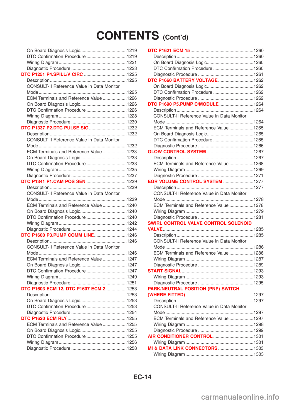
On Board Diagnosis Logic.....................................1219
DTC Confirmation Procedure ................................1219
Wiring Diagram ......................................................1221
Diagnostic Procedure ............................................1223
DTC P1251 P4.SPILL/V CIRC..................................1225
Description .............................................................1225
CONSULT-II Reference Value in Data Monitor
Mode ......................................................................1225
ECM Terminals and Reference Value ...................1226
On Board Diagnosis Logic.....................................1226
DTC Confirmation Procedure ................................1226
Wiring Diagram ......................................................1228
Diagnostic Procedure ............................................1230
DTC P1337 P2.DTC PULSE SIG..............................1232
Description .............................................................1232
CONSULT-II Reference Value in Data Monitor
Mode ......................................................................1232
ECM Terminals and Reference Value ...................1233
On Board Diagnosis Logic.....................................1233
DTC Confirmation Procedure ................................1233
Wiring Diagram ......................................................1235
Diagnostic Procedure ............................................1237
DTC P1341 P1.CAM POS SEN................................1239
Description .............................................................1239
CONSULT-II Reference Value in Data Monitor
Mode ......................................................................1239
ECM Terminals and Reference Value ...................1240
On Board Diagnosis Logic.....................................1240
DTC Confirmation Procedure ................................1240
Wiring Diagram ......................................................1242
Diagnostic Procedure ............................................1244
DTC P1600 P3.PUMP COMM LINE..........................1246
Description .............................................................1246
CONSULT-II Reference Value in Data Monitor
Mode ......................................................................1246
ECM Terminals and Reference Value ...................1247
On Board Diagnosis Logic.....................................1247
DTC Confirmation Procedure ................................1247
Wiring Diagram ......................................................1249
Diagnostic Procedure ............................................1251
DTC P1603 ECM 12, DTC P1607 ECM 2.................1253
Description .............................................................1253
On Board Diagnosis Logic.....................................1253
DTC Confirmation Procedure ................................1253
Diagnostic Procedure ............................................1254
DTC P1620 ECM RLY...............................................1255
ECM Terminals and Reference Value ...................1255
On Board Diagnosis Logic.....................................1255
DTC Confirmation Procedure ................................1255
Wiring Diagram ......................................................1256
Diagnostic Procedure ............................................1258DTC P1621 ECM 15..................................................1260
Description .............................................................1260
On Board Diagnosis Logic.....................................1260
DTC Confirmation Procedure ................................1260
Diagnostic Procedure ............................................1261
DTC P1660 BATTERY VOLTAGE............................1262
On Board Diagnosis Logic.....................................1262
DTC Confirmation Procedure ................................1262
Diagnostic Procedure ............................................1262
DTC P1690 P5.PUMP C/MODULE...........................1264
Description .............................................................1264
CONSULT-II Reference Value in Data Monitor
Mode ......................................................................1264
ECM Terminals and Reference Value ...................1265
On Board Diagnosis Logic.....................................1265
DTC Confirmation Procedure ................................1265
Diagnostic Procedure ............................................1266
GLOW CONTROL SYSTEM.....................................1267
Description .............................................................1267
ECM Terminals and Reference Value ...................1268
Wiring Diagram ......................................................1269
Diagnostic Procedure ............................................1271
EGR VOLUME CONTROL SYSTEM........................1277
Description .............................................................1277
CONSULT-II Reference Value in Data Monitor
Mode ......................................................................1278
ECM Terminals and Reference Value ...................1278
Wiring Diagram ......................................................1279
Diagnostic Procedure ............................................1281
SWIRL CONTROL VALVE CONTROL SOLENOID
VALVE........................................................................1285
Description .............................................................1285
CONSULT-II Reference Value in Data Monitor
Mode ......................................................................1286
ECM Terminals and Reference Value ...................1286
Wiring Diagram ......................................................1287
Diagnostic Procedure ............................................1289
START SIGNAL.........................................................1293
Wiring Diagram ......................................................1293
Diagnostic Procedure ............................................1295
PARK/NEUTRAL POSITION (PNP) SWITCH
(WHERE FITTED)......................................................1297
Description .............................................................1297
CONSULT-II Reference Value in Data Monitor
Mode ......................................................................1297
ECM Terminals and Reference Value ...................1297
Wiring Diagram ......................................................1298
Diagnostic Procedure ............................................1299
AIR CONDITIONER CONTROL................................1301
Wiring Diagram ......................................................1301
MI & DATA LINK CONNECTORS............................1303
Wiring Diagram ......................................................1303
CONTENTS(Cont'd)
EC-14
Page 478 of 3051
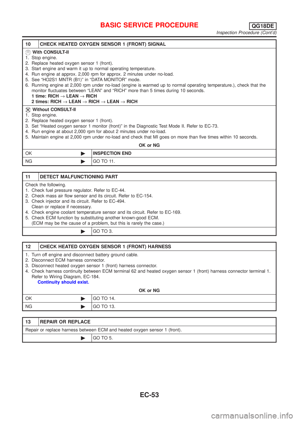
10 CHECK HEATED OXYGEN SENSOR 1 (FRONT) SIGNAL
With CONSULT-II
1. Stop engine.
2. Replace heated oxygen sensor 1 (front).
3. Start engine and warm it up to normal operating temperature.
4. Run engine at approx. 2,000 rpm for approx. 2 minutes under no-load.
5. See ªHO2S1 MNTR (B1)º in ªDATA MONITORº mode.
6. Running engine at 2,000 rpm under no-load (engine is warmed up to normal operating temperature.), check that the
monitor fluctuates between ªLEANº and ªRICHº more than 5 times during 10 seconds.
1 time: RICH®LEAN®RICH
2 times: RICH®LEAN®RICH®LEAN®RICH
Without CONSULT-II
1. Stop engine.
2. Replace heated oxygen sensor 1 (front).
3. Set ªHeated oxygen sensor 1 monitor (front)º in the Diagnostic Test Mode II. Refer to EC-73.
4. Run engine at about 2,000 rpm for about 2 minutes under no-load.
5. Maintain engine at 2,000 rpm under no-load and check that MI goes on more than five times within 10 seconds.
OK or NG
OK©INSPECTION END
NG©GO TO 11.
11 DETECT MALFUNCTIONING PART
Check the following.
1. Check fuel pressure regulator. Refer to EC-44.
2. Check mass air flow sensor and its circuit. Refer to EC-154.
3. Check injector and its circuit. Refer to EC-494.
Clean or replace if necessary.
4. Check engine coolant temperature sensor and its circuit. Refer to EC-169.
5. Check ECM function by substituting another known-good ECM.
(ECM may be the cause of a problem, but this is rarely the case.)
©GO TO 3.
12 CHECK HEATED OXYGEN SENSOR 1 (FRONT) HARNESS
1. Turn off engine and disconnect battery ground cable.
2. Disconnect ECM harness connector.
3. Disconnect heated oxygen sensor 1 (front) harness connector.
4. Check harness continuity between ECM terminal 62 and heated oxygen sensor 1 (front) harness connector terminal 1.
Refer to Wiring Diagram, EC-184.
Continuity should exist.
OK or NG
OK©GO TO 14.
NG©GO TO 13.
13 REPAIR OR REPLACE
Repair or replace harness between ECM and heated oxygen sensor 1 (front).
©GO TO 5.
BASIC SERVICE PROCEDUREQG18DE
Inspection Procedure (Cont'd)
EC-53
Page 571 of 3051
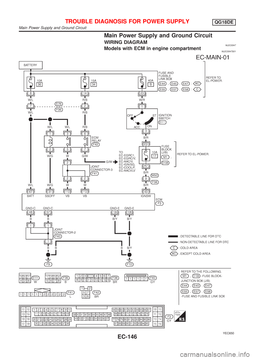
Main Power Supply and Ground Circuit
WIRING DIAGRAMNLEC0047Models with ECM in engine compartmentNLEC0047S01
YEC650
TROUBLE DIAGNOSIS FOR POWER SUPPLYQG18DE
Main Power Supply and Ground Circuit
EC-146
Page 574 of 3051
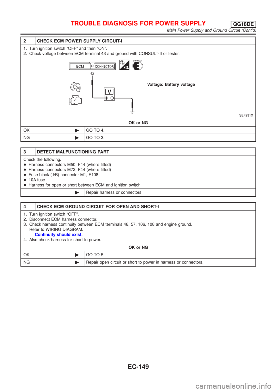
2 CHECK ECM POWER SUPPLY CIRCUIT-I
1. Turn ignition switch ªOFFº and then ªONº.
2. Check voltage between ECM terminal 43 and ground with CONSULT-II or tester.
SEF291X
OK or NG
OK©GO TO 4.
NG©GO TO 3.
3 DETECT MALFUNCTIONING PART
Check the following.
+Harness connectors M50, F44 (where fitted)
+Harness connectors M72, F44 (where fitted)
+Fuse block (J/B) connector M1, E108
+10A fuse
+Harness for open or short between ECM and ignition switch
©Repair harness or connectors.
4 CHECK ECM GROUND CIRCUIT FOR OPEN AND SHORT-I
1. Turn ignition switch ªOFFº.
2. Disconnect ECM harness connector.
3. Check harness continuity between ECM terminals 48, 57, 106, 108 and engine ground.
Refer to WIRING DIAGRAM.
Continuity should exist.
4. Also check harness for short to power.
OK or NG
OK©GO TO 5.
NG©Repair open circuit or short to power in harness or connectors.
TROUBLE DIAGNOSIS FOR POWER SUPPLYQG18DE
Main Power Supply and Ground Circuit (Cont'd)
EC-149
Page 577 of 3051
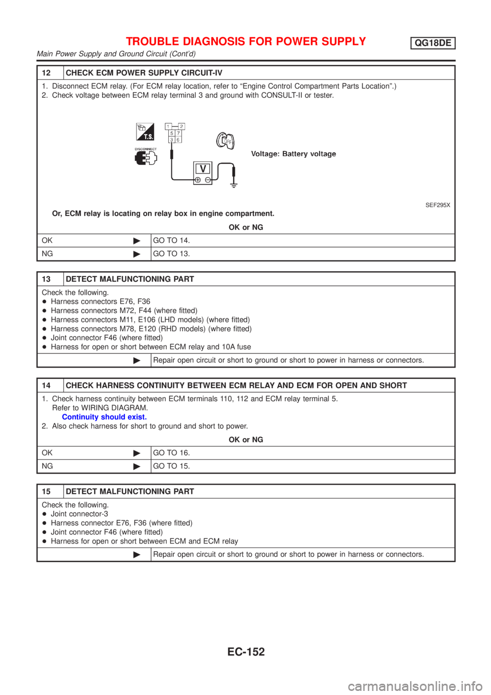
12 CHECK ECM POWER SUPPLY CIRCUIT-IV
1. Disconnect ECM relay. (For ECM relay location, refer to ªEngine Control Compartment Parts Locationº.)
2. Check voltage between ECM relay terminal 3 and ground with CONSULT-II or tester.
SEF295X
Or, ECM relay is locating on relay box in engine compartment.
OK or NG
OK©GO TO 14.
NG©GO TO 13.
13 DETECT MALFUNCTIONING PART
Check the following.
+Harness connectors E76, F36
+Harness connectors M72, F44 (where fitted)
+Harness connectors M11, E106 (LHD models) (where fitted)
+Harness connectors M78, E120 (RHD models) (where fitted)
+Joint connector F46 (where fitted)
+Harness for open or short between ECM relay and 10A fuse
©Repair open circuit or short to ground or short to power in harness or connectors.
14 CHECK HARNESS CONTINUITY BETWEEN ECM RELAY AND ECM FOR OPEN AND SHORT
1. Check harness continuity between ECM terminals 110, 112 and ECM relay terminal 5.
Refer to WIRING DIAGRAM.
Continuity should exist.
2. Also check harness for short to ground and short to power.
OK or NG
OK©GO TO 16.
NG©GO TO 15.
15 DETECT MALFUNCTIONING PART
Check the following.
+Joint connector-3
+Harness connector E76, F36 (where fitted)
+Joint connector F46 (where fitted)
+Harness for open or short between ECM and ECM relay
©Repair open circuit or short to ground or short to power in harness or connectors.
TROUBLE DIAGNOSIS FOR POWER SUPPLYQG18DE
Main Power Supply and Ground Circuit (Cont'd)
EC-152
Page 578 of 3051
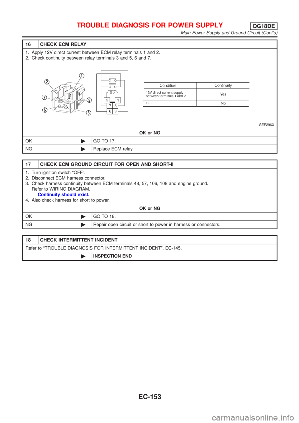
16 CHECK ECM RELAY
1. Apply 12V direct current between ECM relay terminals 1 and 2.
2. Check continuity between relay terminals 3 and 5, 6 and 7.
SEF296X
OK or NG
OK©GO TO 17.
NG©Replace ECM relay.
17 CHECK ECM GROUND CIRCUIT FOR OPEN AND SHORT-II
1. Turn ignition switch ªOFFº.
2. Disconnect ECM harness connector.
3. Check harness continuity between ECM terminals 48, 57, 106, 108 and engine ground.
Refer to WIRING DIAGRAM.
Continuity should exist.
4. Also check harness for short to power.
OK or NG
OK©GO TO 18.
NG©Repair open circuit or short to power in harness or connectors.
18 CHECK INTERMITTENT INCIDENT
Refer to ªTROUBLE DIAGNOSIS FOR INTERMITTENT INCIDENTº, EC-145.
©INSPECTION END
TROUBLE DIAGNOSIS FOR POWER SUPPLYQG18DE
Main Power Supply and Ground Circuit (Cont'd)
EC-153
Page 581 of 3051
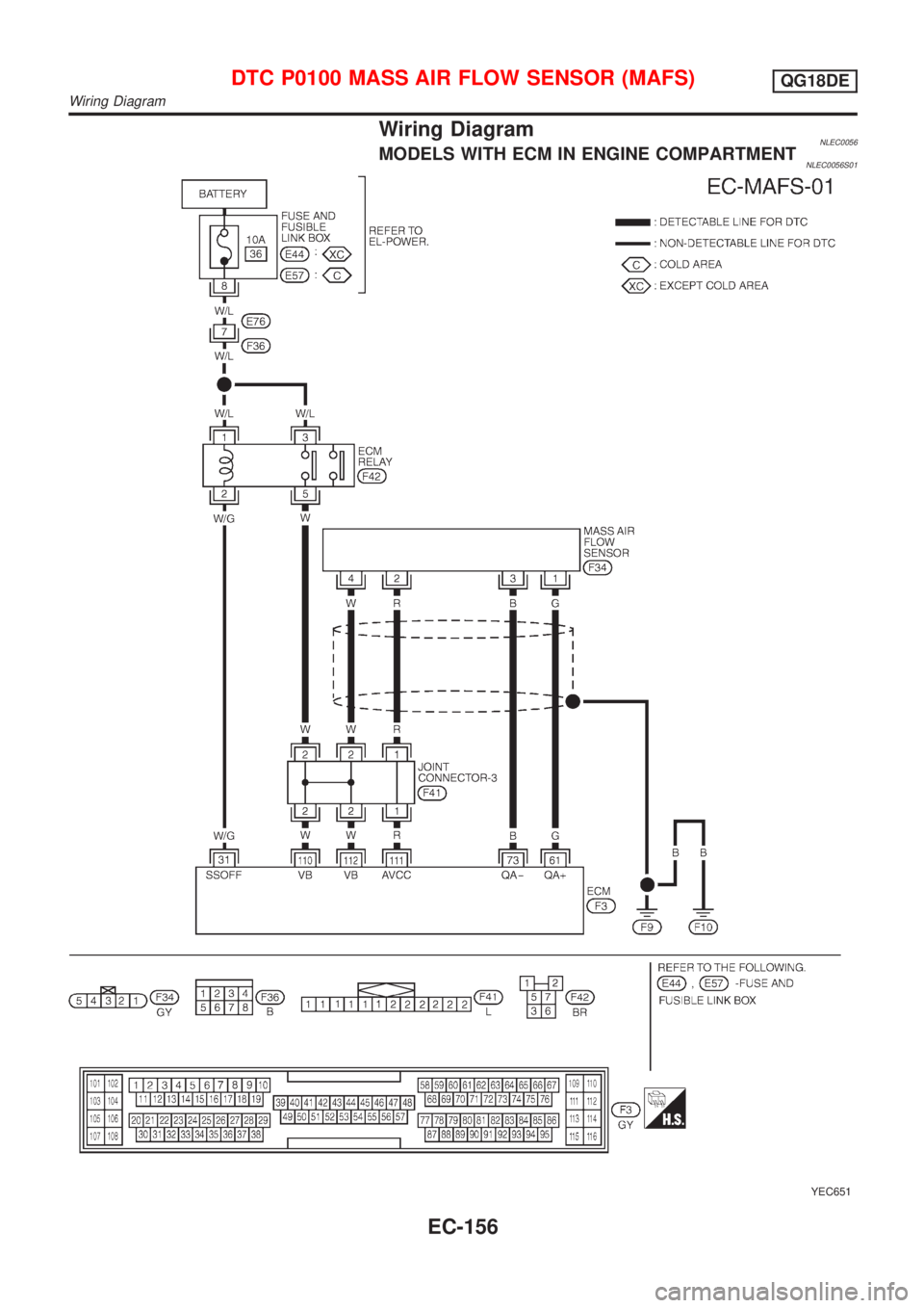
Wiring DiagramNLEC0056MODELS WITH ECM IN ENGINE COMPARTMENTNLEC0056S01
YEC651
DTC P0100 MASS AIR FLOW SENSOR (MAFS)QG18DE
Wiring Diagram
EC-156
Page 582 of 3051
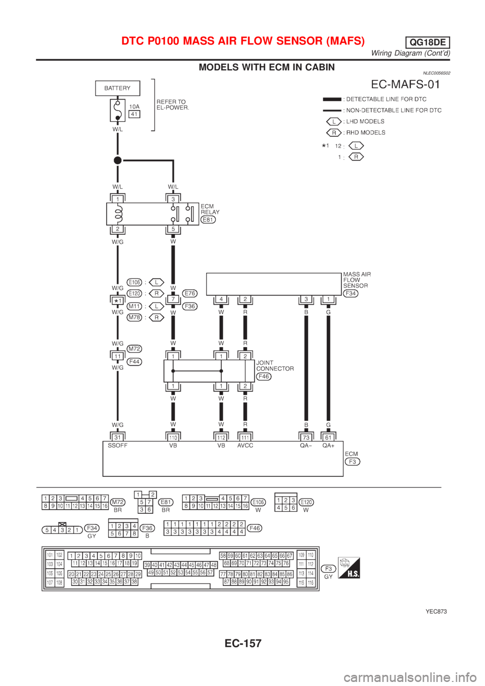
MODELS WITH ECM IN CABINNLEC0056S02
YEC873
DTC P0100 MASS AIR FLOW SENSOR (MAFS)QG18DE
Wiring Diagram (Cont'd)
EC-157